EP2587609A1 - Stromversorgungsvorrichtung und -verfahren - Google Patents
Stromversorgungsvorrichtung und -verfahren Download PDFInfo
- Publication number
- EP2587609A1 EP2587609A1 EP10782518.4A EP10782518A EP2587609A1 EP 2587609 A1 EP2587609 A1 EP 2587609A1 EP 10782518 A EP10782518 A EP 10782518A EP 2587609 A1 EP2587609 A1 EP 2587609A1
- Authority
- EP
- European Patent Office
- Prior art keywords
- path
- power
- utility grid
- direct
- section
- Prior art date
- Legal status (The legal status is an assumption and is not a legal conclusion. Google has not performed a legal analysis and makes no representation as to the accuracy of the status listed.)
- Granted
Links
Images


Classifications
-
- H—ELECTRICITY
- H02—GENERATION; CONVERSION OR DISTRIBUTION OF ELECTRIC POWER
- H02J—ELECTRIC POWER NETWORKS; CIRCUIT ARRANGEMENTS OR SYSTEMS FOR SUPPLYING OR DISTRIBUTING ELECTRIC POWER; SYSTEMS FOR STORING ELECTRIC ENERGY
- H02J3/00—Circuit arrangements for AC mains or AC distribution networks
- H02J3/38—Arrangements for feeding a single network from two or more generators or sources in parallel; Arrangements for feeding already energised networks from additional generators or sources in parallel
-
- H—ELECTRICITY
- H02—GENERATION; CONVERSION OR DISTRIBUTION OF ELECTRIC POWER
- H02J—ELECTRIC POWER NETWORKS; CIRCUIT ARRANGEMENTS OR SYSTEMS FOR SUPPLYING OR DISTRIBUTING ELECTRIC POWER; SYSTEMS FOR STORING ELECTRIC ENERGY
- H02J3/00—Circuit arrangements for AC mains or AC distribution networks
- H02J3/38—Arrangements for feeding a single network from two or more generators or sources in parallel; Arrangements for feeding already energised networks from additional generators or sources in parallel
- H02J3/381—Dispersed generators
-
- H—ELECTRICITY
- H02—GENERATION; CONVERSION OR DISTRIBUTION OF ELECTRIC POWER
- H02J—ELECTRIC POWER NETWORKS; CIRCUIT ARRANGEMENTS OR SYSTEMS FOR SUPPLYING OR DISTRIBUTING ELECTRIC POWER; SYSTEMS FOR STORING ELECTRIC ENERGY
- H02J3/00—Circuit arrangements for AC mains or AC distribution networks
- H02J3/38—Arrangements for feeding a single network from two or more generators or sources in parallel; Arrangements for feeding already energised networks from additional generators or sources in parallel
- H02J3/46—Controlling the sharing of generated power between the generators, sources or networks
-
- H—ELECTRICITY
- H02—GENERATION; CONVERSION OR DISTRIBUTION OF ELECTRIC POWER
- H02J—ELECTRIC POWER NETWORKS; CIRCUIT ARRANGEMENTS OR SYSTEMS FOR SUPPLYING OR DISTRIBUTING ELECTRIC POWER; SYSTEMS FOR STORING ELECTRIC ENERGY
- H02J9/00—Circuit arrangements for emergency or stand-by power supply, e.g. for emergency lighting
- H02J9/04—Circuit arrangements for emergency or stand-by power supply, e.g. for emergency lighting in which the distribution system is disconnected from the normal source and connected to a standby source
- H02J9/06—Circuit arrangements for emergency or stand-by power supply, e.g. for emergency lighting in which the distribution system is disconnected from the normal source and connected to a standby source with automatic change-over, e.g. UPS systems
- H02J9/062—Circuit arrangements for emergency or stand-by power supply, e.g. for emergency lighting in which the distribution system is disconnected from the normal source and connected to a standby source with automatic change-over, e.g. UPS systems for AC powered loads
-
- H—ELECTRICITY
- H02—GENERATION; CONVERSION OR DISTRIBUTION OF ELECTRIC POWER
- H02J—ELECTRIC POWER NETWORKS; CIRCUIT ARRANGEMENTS OR SYSTEMS FOR SUPPLYING OR DISTRIBUTING ELECTRIC POWER; SYSTEMS FOR STORING ELECTRIC ENERGY
- H02J2101/00—Supply or distribution of decentralised, dispersed or local electric power generation
- H02J2101/10—Dispersed power generation using fossil fuels, e.g. diesel generators
-
- H—ELECTRICITY
- H02—GENERATION; CONVERSION OR DISTRIBUTION OF ELECTRIC POWER
- H02J—ELECTRIC POWER NETWORKS; CIRCUIT ARRANGEMENTS OR SYSTEMS FOR SUPPLYING OR DISTRIBUTING ELECTRIC POWER; SYSTEMS FOR STORING ELECTRIC ENERGY
- H02J2101/00—Supply or distribution of decentralised, dispersed or local electric power generation
- H02J2101/20—Dispersed power generation using renewable energy sources
- H02J2101/28—Wind energy
Definitions
- the present invention relates to power supply devices and methods.
- Wind turbine generators that generate electricity by means of natural energy, namely, wind force, are conventionally known.
- a rotor head equipped with wind turbine rotating blades, a main shaft coupled to the rotor head so as to rotate together therewith, a gearbox to which the main shaft is coupled so as to rotate as the wind turbine rotating blades receive wind force, and a generator driven by the shaft output of the gearbox are provided on a nacelle mounted on a tower.
- the rotor head equipped with the wind turbine rotating blades, which convert wind force into torque, and the main shaft are rotated to generate a shaft output, and the gearbox coupled to the main shaft transfers the shaft output to the generator while increasing the rotational speed thereof.
- the shaft output generated by converting wind force into torque serves as a driving source for the generator, and wind force can be used as a power source for the generator to generate electricity.
- Patent Literature 1 proposes a technique for supplying power from a DC link (direct-current link) to auxiliary machines in an AC-DC-AC wind turbine generator with variable speed control of a generator.
- Patent Literature 1 has a problem in that a single path for supplying power to the auxiliary machines is provided from the DC link, without redundancy.
- An object of the present invention which has been made to solve the above problem, is to provide a power supply device and method that allow a duplex auxiliary machine power supply to be configured.
- a first aspect of the present invention is a power supply device applied to a power generation system including a power generation apparatus for generating electricity by means of natural energy and a power-converting section including a first converter for converting alternating-current power received from the power generation apparatus into direct-current power and a second converter for converting the direct-current power into alternating-current power matching the frequency of a utility grid, to supply power to auxiliary machines for the power generation apparatus.
- the power supply device includes a switching section that is connected to a first path connected to a direct-current link between the first converter and the second converter via a third converter for converting direct-current power supplied from the direct-current link into alternating-current power, that is connected to a second path connected somewhere between the power-converting section and the utility grid, and that is connected to a third path connected to the auxiliary machines, and the switching section switches between connection of the third path to the first path and connection of the third path to the second path, depending on demand at the utility grid.
- alternating-current power generated by means of natural energy is converted into direct-current power by the first converter and is converted into alternating-current power matching the frequency of the utility grid by the second converter.
- the first path is formed by connecting the direct-current link between the first converter and the second converter to the switching section via the third converter for converting the direct-current power supplied from the direct-current link into alternating-current power
- the second path is formed by connecting somewhere between the power-converting section and the utility grid to the switching section
- the third path is formed by connecting the switching section to the auxiliary machines.
- the switching section is switched to switch between the connection of the third path to the first path and the connection of the third path to the second path.
- the power supplied to the auxiliary machines can be supplied either from the direct-current link of the power-converting section or from the line between the power-converting section and the utility grid. Accordingly, a plurality of paths for supplying power to the auxiliary machines can be formed, thus providing a redundant auxiliary machine power supply.
- the second path is not connected to the third path and therefore does not supply power to the auxiliary machines, thus allowing an inspection procedure on a breaker, a lamp, etc. provided in the second path.
- a control section that controls the switching section depending on at least one of the status of the utility grid and the status of the direct-current link may be provided. Because the switching section is controlled depending on at least one of the status of the utility grid (for example, grid frequency or voltage) and the status of the direct-current link (for example, the presence or absence of an abnormal condition in the direct-current link), the control can be performed such that, for example, the switching section is switched so as to supply the auxiliary machines with power from the direct-current link if the frequency of the utility grid becomes unstable and is switched so as to supply the auxiliary machines with power from the utility grid if the direct-current link is in an abnormal condition, thus continuing the operation of the auxiliary machines.
- the switching section is controlled depending on at least one of the status of the utility grid (for example, grid frequency or voltage) and the status of the direct-current link (for example, the presence or absence of an abnormal condition in the direct-current link)
- the control can be performed such that, for example, the switching section is switched so as to supply the auxiliary machines with
- control section connects the third path to the first path by synchronous switching of the switching section if at least one of the frequency and voltage at the utility grid is predicted to vary by a predetermined amount or more.
- the third path is connected to the first path by synchronous switching if the frequency or voltage at the utility grid is predicted to vary by a predetermined amount or more. For example, if lightning is predicted according to weather information, and it is predicted to cause frequency variations or voltage variations at the utility grid, the auxiliary machines can be supplied with power from the direct-current link so that they can continue to operate irrespective of changes in the status of the utility grid.
- synchronous switching can be selected because the switching is performed according to prediction in advance with sufficient time before the weather information changes, thus allowing switching without momentary interruption.
- the second path is connected to the third path in normal operation, and the control section controls the switching section so as to connect the first path to the third path if the frequency of the utility grid is at or above a first predetermined range serving as an allowable range of variation.
- the second path is connected to the third path in normal operation, and switching is performed so as to supply the auxiliary machines with power from the direct-current line of the power-converting section if a variation in the frequency of the utility grid is at or above the first predetermined range.
- the auxiliary machines can be supplied with power from the power-converting section by switching the switching section to continue supplying power to the auxiliary machines while operating the power generation apparatus, thus preventing the auxiliary machines from stopping.
- the normal operation means operation without variations in the frequency of the utility grid.
- the second path is connected to the third path in normal operation, and the control section controls the switching section so as to connect the second path to the third path if the frequency of the utility grid is at or below a second predetermined range smaller than a first predetermined range serving as an allowable range of variation.
- the auxiliary machines are supplied with power from somewhere between the power-converting section and the utility grid if the frequency falls within the second predetermined range smaller than the first predetermined range.
- hysteresis can be implemented by setting the second predetermined range to a range smaller than the first predetermined range, thus stabilizing the switching control.
- the normal operation means operation without variations in the frequency of the utility grid (at or below the second predetermined range).
- the control section measures the period of a variation in the frequency of the utility grid and controls the switching section depending on the period of the variation. Because the switching section is controlled depending on the period of a variation in the frequency of the utility grid (the period during which the frequency is at or above the first predetermined range and the period during which the frequency is at or below the second predetermined range), the control can be performed such that, for example, the switching section is not switched if a variation in the frequency of the utility grid occurs but subsides instantly and is switched if the variation continues for a predetermined time (for example, ten seconds). This prevents frequent switching due to, for example, false detection of frequency variations, thus improving the accuracy of the switching control.
- a predetermined time for example, ten seconds
- the second path is connected to the third path in normal operation, and the control section controls the switching section so as to connect the first path to the third path if the voltage of the utility grid is at or above a third predetermined range serving as an allowable range of variation.
- Switching is performed so as to supply the auxiliary machines with power from the direct-current line of the power-converting section if a variation in the voltage of the utility grid is at or above the third predetermined range.
- the auxiliary machines can be supplied with power from the power-converting section by switching the switching section to continue supplying power to the auxiliary machines while operating the power generation apparatus, thus preventing the auxiliary machines from stopping.
- the normal operation means operation without variations in the voltage of the utility grid.
- the second path is connected to the third path in normal operation, and the control section controls the switching section so as to connect the second path to the third path if the voltage of the utility grid is at or below a fourth predetermined range smaller than a third predetermined range serving as an allowable range of variation.
- the auxiliary machines are supplied with power from somewhere between the power-converting section and the utility grid, rather than from the power-converting section, if the voltage falls within the fourth predetermined range smaller than the third predetermined range.
- hysteresis can be implemented by setting the fourth predetermined range to a range smaller than the third predetermined range, thus stabilizing the switching control.
- the normal operation means operation without variations in the voltage of the utility grid (at or below the fourth predetermined range).
- the control section measures the period of a variation in the voltage of the utility grid and controls the switching section depending on the period of the variation. Because the switching section is controlled depending on the period during which the voltage is at or above the third predetermined range and the period during which the voltage is at or below the fourth predetermined range, the control can be performed such that, for example, the switching section is not switched if a variation in the voltage of the utility grid occurs but subsides instantly and is switched if the variation continues for a predetermined time (for example, ten seconds). This prevents frequent switching due to, for example, false detection of voltage variations, thus improving the accuracy of the switching control.
- a predetermined time for example, ten seconds
- the first path is connected to the third path in normal operation, and the control section controls the switching section so as to connect the second path to the third path if it is detected that the direct-current link of the power-converting section is in an abnormal condition.
- the auxiliary machines are supplied with power from the utility grid if the direct-current link of the power-converting section is in an abnormal condition, thus allowing power to be supplied to the auxiliary machines irrespective of an abnormal condition in the direct-current link.
- the control section controls the switching section so as to connect the first path to the third path if it is detected that the direct-current link of the power-converting section is not in an abnormal condition after the switching section connects the second path to the third path upon detection of an abnormal condition in the direct-current link.
- the connection for supplying power from the direct-current link can be reliably restored by synchronous switching if it is detected that the direct-current link of the power-converting section is not in an abnormal condition, thus allowing power to be stably supplied to the auxiliary machines irrespective of the presence or absence of frequency or voltage variations at the utility grid.
- the auxiliary machines include a first auxiliary machine group connected to the switching section and a second auxiliary machine group connected, without the switching section, somewhere between the power-converting section and the utility grid, the auxiliary machines included in the second auxiliary machine group are auxiliary machines that do not affect the operation of the power generation apparatus when stopped, and the auxiliary machines included in the first auxiliary machine group are auxiliary machines other than the second auxiliary machine group.
- the size of the third converter can be reduced. Accordingly, a less expensive third inverter ean be used than that used for supplying all auxiliary machines with power from the direct-current link.
- the first auxiliary machine group includes auxiliary machines required to operate constantly, such as a governing oil pump and a lubricant oil pump
- the second auxiliary machine group includes auxiliary machines that operate intermittently, such as a ventilating fan and a generator-cooling fan.
- a second aspect of the present invention is a power supply method applied to a power generation system including a power generation apparatus for generating electricity by means of natural energy and a power-converting section including a first converter for converting alternating-current power received from the power generation apparatus into direct-current power and a second converter for converting the direct-current power into alternating-current power matching the frequency of a utility grid, to supply power to auxiliary machines for the power generation apparatus.
- a connection to a direct-current link between the first converter and the second converter via a third converter for converting direct-current power supplied from the direct-current link into alternating-current power is provided to form a first path
- a connection to somewhere between the power-converting section and the utility grid is provided to form a second path
- a connection to the auxiliary machines is provided to form a third path
- switching is performed between connection of the third path to the first path and connection of the third path to the second path, depending on demand at the utility grid.
- alternating-current power generated by means of natural energy is converted into direct-current power by the first converter and is converted into alternating-current power matching the frequency of the utility grid by the second converter.
- the first path is formed by providing a connection to the direct-current link between the first converter and the second converter via the third converter for converting the direct-current power supplied from the direct-current link into alternating-current power
- the second path is formed by connecting somewhere between the power-converting section and the utility grid to the switching section
- the third path is formed by connecting the switching section to the auxiliary machines.
- the switching is performed between the connection of the third path to the first path and the connection of the third path to the second path.
- the power supplied to the auxiliary machines can be supplied either from the direct-current link of the power-converting section or from the line between the power-converting section and the utility grid so that a plurality of paths for supplying power to the auxiliary machines can be formed, thus providing a redundant auxiliary machine power supply.
- the second path is not connected to the third path and therefore does not supply power to the auxiliary machines, thus allowing an inspection procedure on a breaker, a lamp, etc. provided in the second path.
- the present invention offers the advantage of providing a duplex auxiliary machine power supply.
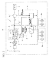
- Fig. 1 is a block diagram schematically showing the configuration of a wind turbine generator system 10 using a power supply device according to this embodiment.
- the wind turbine generator system 10 includes a wind turbine generator 1 and a power supply device 9.
- the wind turbine generator 1 includes wind turbine blades 2, a gearbox 3, a generator 4, a power-converting section 5, a grid frequency sensor 6, and auxiliary machines 8.
- the wind turbine blades 2 are attached to a wind turbine rotor (not shown).
- the generator 4 is connected to a main shaft of the wind turbine rotor via the gearbox 3, which has a predetermined gear ratio.
- the generator 4 is connected to a utility grid 7 via the power-converting section 5. The force of wind striking the wind turbine blades 2 in the rotation axis direction of the wind turbine rotor is converted into power for rotating the wind turbine rotor about the rotation axis direction, and the power is in turn converted into electrical energy by the generator 4.
- the power-converting section 5 includes a generator-side inverter (first converter) 11, a direct-current link 12, and a grid-side inverter (second converter) 13 and converts alternating-current power received from the generator side into alternating-current power matching the frequency of the utility grid 7.
- the generator-side inverter 11 converts alternating-current power generated by the generator 4 into direct-current power and outputs the direct-current power to the direct-current link 12.
- the grid-side inverter 13 converts direct-current power received from the direct-current link 12 into alternating-current power having the same frequency as the utility grid 7 and outputs the alternating-current power.
- the power-converting section 5 also has the function of converting alternating-current power received from the utility grid 7 into alternating-current power matching the frequency of the generator 4.
- the grid-side inverter 13 converts alternating-current power into direct-current power and outputs the direct-current power to the direct-current link 12.
- the generator-side inverter 11 converts direct-current power received from the direct-current link 12 into alternating-current power matching the frequency of the generator 4 and supplies the alternating-current power to the generator 4.
- the power converter 5 (AC-DC-AC link) for converting the output of the generator 4 into direct current and then converting it into alternating current again with an inverter is connected to the stator side of the generator 4 for speed control etc.
- the grid frequency sensor 6 measures the frequency at the utility grid 7 and outputs information about the measured grid frequency to the power supply device 9.
- the power supply device 9 includes an auxiliary machine power inverter (third converter) 14, a switching section 15, and a control section 16.
- the auxiliary machine power inverter 14 converts direct-current power supplied from the direct-current link 12 between the generator-side inverter 11 and the grid-side inverter 13 into alternating-current power.
- the auxiliary machine power inverter 14 operates constantly for phase synchronization with the voltage at the utility grid 7.
- the switching section 15 is connected to the direct-current link 12 via the auxiliary machine power inverter 14 to form a first path A, is connected somewhere between the power-converting section 5 and the utility grid 7 (for example, a node X in Fig. 1 ) to form a second path B, and is connected to the auxiliary machines 8 (or an auxiliary machine power supply for supplying power to the auxiliary machines) to form a third path C, and the switching section 15 switches between the connection of the third path C to the first path A and the connection of the third path C to the second path B, depending on the demand at the utility grid 7.
- a breaker, a lamp, etc. are provided in the second path B.
- the normal operation means that the grid frequency or grid voltage varies within a predetermined range.
- the switching section 15 disconnects the second path B from the third path C in order to connect the first path A to the third path C, and disconnects the first path A from the third path C in order to connect the second path B to the third path C.
- the switching section 15 of this embodiment is described as a switch involving momentary interruption, the switching section 15 is not limited thereto.
- a line filter (noise filter) is preferably provided downstream of the switching section 15 (i.e., on the auxiliary machine 8 side). This reduces noise occurring on the auxiliary machine 8 side when the connection at the switching section 15 is switched.
- the control section 16 controls the switching section 15 so as to connect the first path A to the third path C if the frequency of the utility grid 7 is at or above a first predetermined range serving as an allowable range of variation.
- the control section 16 may control the switching section 15 so as to connect the second path B to the third path C if the frequency of the utility grid 7 is at or below a second predetermined range smaller than the first predetermined range serving as an allowable range of variation.
- hysteresis may be implemented by the above first and second predetermined ranges to prevent frequent switching at the switching section 15, thus stabilizing the control.
- the above first and second predetermined ranges of frequency variation are preferably between +3% and -5% and within ⁇ 2%, respectively, with respect to the rated frequency.
- control section 16 may measure the period of a variation in the frequency of the utility grid 7 and control the switching section 15 depending on the period of the variation.
- the first predetermined range is from 0.95 pu to 1.03 pu
- the control section 16 controls the switching section 15 so as to connect the first path A to the third path C if the period during which the grid frequency is beyond the first predetermined range, namely, at or below 0.95 pu or at or above 1.03 pu, continues for ten seconds.
- the second predetermined range is from 0.95 pu to 1.03 pu
- the control section 16 controls the switching section 15 so as to connect the second path B to the third path C if the period during which the grid frequency falls within the second predetermined range continues for three or more seconds.
- equipment such as an interactive chopper, intended to control the current or voltage between the auxiliary machine power inverter 14 and the direct-current link 12 is inserted between the auxiliary machine power inverter 14 and the direct-current link 12.
- the switching section 15 connects the second path B to the third path C to supply the auxiliary machines 8 with alternating-current power from the node X between the power-converting section 5 and the utility grid 7.
- the grid frequency sensor 6 detects the frequency at the utility grid 7
- the information about the grid frequency is output to the power supply device 9.
- the control section 16 of the power supply device 9 determines whether or not the frequency of the utility grid 7 falls within the first predetermined range, which serves as an allowable range of variation, and, if it determines that the frequency is beyond the first predetermined range, outputs a switching command to the switching section 15.
- the switching section 15 Upon reception of the switching command, the switching section 15 connects the first path A to the third path C.
- the auxiliary machines 8 are supplied with power from the generator 4 via the direct-current link 12 and the auxiliary machine power inverter 14. In this way, if a variation in the grid frequency at the utility grid 7 is beyond the allowable range, the power supply from the utility grid 7 to the auxiliary machines 8 is switched to the power supply from the direct-current link 12 of the power-converting section 5 to the auxiliary machines 8.
- the auxiliary machines 8 can continue to operate irrespective of frequency variations on the utility grid 7 even if an abnormal condition occurs at the utility grid 7 and causes frequency variations contributing to a malfunction of the auxiliary machines 8.
- control section 16 determines whether or not the frequency of the utility grid 7 falls within the first predetermined range (or the second predetermined range), serving as an allowable range of variation, and the control section 16 outputs a switching command to the switching section 15 if it determines that the frequency falls within the first predetermined range (or the second predetermined range). Upon reception of the switching command, the switching section 15 connects the second path B to the third path C.
- alternating-current power generated by means of natural energy is converted into direct-current power by the generator-side inverter 11 and is converted into alternating-current power matching the frequency of the utility grid 7 by the grid-side inverter 13.
- the first path A is formed by connecting the direct-current link 12 between the generator-side inverter 11 and the grid-side inverter 13 to the switching section 15 via the auxiliary machine power inverter 14 for converting the direct-current power supplied from the direct-current link into alternating-current power
- the second path B is formed by connecting somewhere between the power-converting section 5 and the utility grid 7 to the switching section 15, and the third path C is formed by connecting the switching section 15 to the auxiliary machines 8.
- the switching section 15 is switched to switch between the connection of the third path C to the first path A and the connection of the third path C to the second path B.
- the power supplied to the auxiliary machines 8 can be supplied either from the direct-current link 12 of the power-converting section 5 or from the line between the power-converting section 5 and the utility grid 7. Accordingly, a plurality of paths for supplying power to the auxiliary machines 8 can be formed, thus providing a redundant auxiliary machine power supply.
- the second path B is not connected to the third path C and therefore does not supply power to the auxiliary machines 8, thus allowing an inspection procedure on the breaker, the lamp, etc. provided in the second path B.
- auxiliary machines 8 are connected via the switching section 15 (the details will be described later) in the description of this embodiment, the connection is not limited thereto.
- the auxiliary machines 8 may be distinguished between a first auxiliary machine group 8a connected to the switching section 15 and a second auxiliary machine group 8b connected, without the switching section 15, somewhere between the power-converting section 5 and the utility grid 7 to supply the auxiliary machine groups 8a and 8b with power from different sources.
- the auxiliary machines included in the second auxiliary machine group 8b are auxiliary machines that do not affect the operation of the wind turbine generator 1 when stopped, whereas the auxiliary machines included in the first auxiliary machine group 8a are auxiliary machines other than the second auxiliary machine group 8b.
- the first auxiliary machine group 8a includes auxiliary machines required to operate constantly, such as a governing oil pump and a lubricant oil pump.
- the second auxiliary machine group 8b includes auxiliary machines that operate intermittently, such as a ventilating fan and a generator-cooling fan.
- the size of the auxiliary machine power inverter 14 of the power supply device 9 required for supplying power can be reduced. Accordingly, a less expensive inverter can be used as the auxiliary machine power inverter 14 of the power supply device 9 than that used as the auxiliary machine power inverter 14 of the power supply device 9 to supply power to all auxiliary machines 8.
- the control method is not limited thereto.
- a grid voltage sensor 6' may be provided instead of the grid frequency sensor 6, and the control section 16 may control the switching section 15 depending on the grid voltage at the utility grid 7 using the grid voltage sensor 6'.
- the control section 16 controls the switching section 15 so as to connect the first path A to the third path C if the voltage of the utility grid 7 is at or above a third predetermined range serving as an allowable range of variation.
- the control section 16 controls the switching section 15 so as to connect the second path B to the third path C if the voltage of the utility grid 7 is at or below a fourth predetermined range smaller than the third predetermined range serving as an allowable range of variation.
- the auxiliary machines 8 can be supplied with power from the direct-current link 12 of the power-converting section 5 by switching the switching section 15 to continue supplying power to the auxiliary machines 8 while operating the wind turbine generator 1, thus preventing the auxiliary machines 8 from stopping.
- a switching section 15' that performs synchronous switching (uninterruptible switching) without momentary interruption during switching may be used instead of the switching section 15 involving momentary interruption.
- uninterruptible switching for example, as shown in Figs. 3A to 3C , a parallel switch is used as the switching section 15' and, if switching is performed from the state where the first path A is connected to the third path C ( Fig. 3A ), the second path B is connected to the third path C, with the first path A being connected to the third path ( Fig.
- the path can be switched stepwise, thus preventing momentary interruption and eliminating the need for a line filter (noise filter).
- the auxiliary machines 8 are supplied with power from the direct-current link 12. In this way, if variations are predicted and accordingly the switching section 15 is switched in advance, the above uninterruptible switching can be performed to continue the operation of the auxiliary machines 8 without momentary interruption.
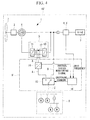
- a power supply device 9' according to a second embodiment of the present invention will be described using Fig. 4 .
- this embodiment differs from the above first embodiment in that the switching timing of the switching section is controlled depending on the status of the auxiliary machine power inverter 14.
- a wind turbine generator system 10' according to this embodiment, a description of the same points as in the first embodiment will be omitted, and different points will be mainly described below.
- a configuration using a wound-rotor induction motor as a generator namely, a double-fed (secondary excitation) wind turbine generator system 10', will be described.
- the normal operation means that the auxiliary machine power inverter 14 is not in an abnormal condition.
- the auxiliary machine power inverter 14 has a self-diagnosis function and notifies a control section 16' about the result of detection.
- the control section 16' receives the result of detection concerning the presence or absence of an abnormal condition from the auxiliary machine power inverter 14 and controls the switching section 15 depending on that result. Specifically, if it is detected that the auxiliary machine power inverter 14 is in an abnormal condition, the control section 16' controls the switching section 15 so as to connect the second path B to the third path C.
- the control section 16' controls the switching section 15 so as to connect the first path A to the third path C.
- the control section 16' monitors the status of the auxiliary machine power inverter 14 (for example, executes determination based on the presence or absence of a notification of the self-diagnosis function) and controls the switching section 15 so as to connect the second path B to the third path C if the auxiliary machine power inverter 14 malfunctions.
- the switching section 15 connects the first path A to the third path C so that the auxiliary machine power inverter 14 converts direct-current power supplied from the direct-current link 12 into alternating-current power and supplies the alternating-current power to the auxiliary machines 8.
- the control section 16' receives the information about the abnormal condition in the auxiliary machine power inverter 14, it outputs, to the switching section 15, a switching command for controlling the switching section 15 so as to connect the second path B to the third path C.
- the switching section is switched to connect the second path B to the third path C so that the auxiliary machines 8 are supplied with alternating-current power from the node X between the power-converting section 5 and the utility grid 7 via the second path B and the third path C.
- the power supply from the direct-current link 12 is switched to the power supply from the utility grid 7 so that the auxiliary machines 8 can continue to operate.
- the control section 16' Based on the information about the normal condition, the control section 16' outputs a switching command for connecting the first path A to the third path C to the switching section 15 to supply the auxiliary machines 8 with power from the direct-current link 12. In the switching section 15, the path is switched on the basis of the received switching command to connect the first path A to the third path C. In this way, if the control section 16' detects a malfunction of the auxiliary machine power inverter 14, it controls the switching section 15 so as to connect the second path B to the third path C. In addition, a breaker, a lamp, etc. are provided in the second path B and, when the breaker, the lamp, etc. are to be inspected, the control section 16' may execute the control so as to connect the first path A to the third path C.
- the auxiliary machines 8 are supplied with power from the utility grid 7 if the auxiliary machine power inverter 14 is in an abnormal condition, thus allowing power to be supplied to the auxiliary machines 8 irrespective of the abnormal condition in the auxiliary machine power inverter 14.
- power can be supplied from the direct-current link 12 if it is detected that the auxiliary machine power inverter 14 is not in an abnormal condition, thus allowing power to be stably supplied to the auxiliary machines 8 irrespective of the presence or absence of frequency or voltage variations at the utility grid 7.
- wind turbine generator 4 generator 5 power-converting section 6 grid frequency sensor 8 auxiliary machine 9 power supply device 10 wind turbine generator system 11 generator-side inverter 12 direct-current link 13 grid-side inverter 14 auxiliary machine power inverter 15 switching section 16 control section
Landscapes
- Engineering & Computer Science (AREA)
- Power Engineering (AREA)
- Business, Economics & Management (AREA)
- Emergency Management (AREA)
- Control Of Eletrric Generators (AREA)
- Supply And Distribution Of Alternating Current (AREA)
Applications Claiming Priority (1)
| Application Number | Priority Date | Filing Date | Title |
|---|---|---|---|
| PCT/JP2010/059104 WO2011148503A1 (ja) | 2010-05-28 | 2010-05-28 | 電力供給装置及び方法 |
Publications (3)
| Publication Number | Publication Date |
|---|---|
| EP2587609A1 true EP2587609A1 (de) | 2013-05-01 |
| EP2587609A4 EP2587609A4 (de) | 2017-08-16 |
| EP2587609B1 EP2587609B1 (de) | 2019-07-31 |
Family
ID=45003509
Family Applications (1)
| Application Number | Title | Priority Date | Filing Date |
|---|---|---|---|
| EP10782518.4A Active EP2587609B1 (de) | 2010-05-28 | 2010-05-28 | Stromversorgungsvorrichtung und -verfahren |
Country Status (8)
| Country | Link |
|---|---|
| EP (1) | EP2587609B1 (de) |
| JP (1) | JP5449204B2 (de) |
| KR (1) | KR101207151B1 (de) |
| CN (1) | CN102754298B (de) |
| AU (1) | AU2010257197A1 (de) |
| BR (1) | BRPI1004906A2 (de) |
| CA (1) | CA2722335A1 (de) |
| WO (1) | WO2011148503A1 (de) |
Cited By (7)
| Publication number | Priority date | Publication date | Assignee | Title |
|---|---|---|---|---|
| CN106099903A (zh) * | 2016-07-25 | 2016-11-09 | 国网河北省电力公司电力科学研究院 | 一种双馈风力发电机并入直流输配电网的并网系统及其控制方法 |
| EP3101772A1 (de) * | 2015-06-05 | 2016-12-07 | General Electric Company | Unterbrechungsfreie stromversorgung und verfahren zur verwendung |
| US9685820B2 (en) | 2014-03-11 | 2017-06-20 | General Electric Company | Redundant uninterruptible power supply systems |
| US9705360B2 (en) | 2014-03-11 | 2017-07-11 | General Electric Company | Redundant uninterruptible power supply systems |
| US9859716B2 (en) | 2015-05-29 | 2018-01-02 | General Electric Company | Hybrid AC and DC distribution system and method of use |
| US9882424B2 (en) | 2014-02-21 | 2018-01-30 | General Electric Company | Redundant uninterruptible power supply systems |
| WO2018063529A1 (en) * | 2016-09-30 | 2018-04-05 | General Electric Company | Electronic sub-system and dfig based power generation system for powering variable frequency electrical devices |
Families Citing this family (6)
| Publication number | Priority date | Publication date | Assignee | Title |
|---|---|---|---|---|
| DK2645530T3 (en) * | 2012-03-27 | 2018-11-12 | Siemens Ag | Method for controlling a wind farm, wind farm controller, wind farm, computer-readable medium and program element |
| CN111386654B (zh) * | 2018-10-29 | 2023-08-04 | 东芝三菱电机产业系统株式会社 | 风力发电系统及电力转换装置 |
| CN111064258B (zh) * | 2019-12-31 | 2022-05-31 | 联想(北京)有限公司 | 一种供电设备及供电方法 |
| FR3109485B1 (fr) * | 2020-04-15 | 2023-05-19 | Safran | Canal de propulsion pour aéronef |
| CN112398318A (zh) * | 2020-10-29 | 2021-02-23 | 星展测控科技股份有限公司 | 电源控制装置及动中通设备 |
| CN118971323A (zh) * | 2024-08-30 | 2024-11-15 | 深圳市裕嘉达科技有限公司 | 一种热备份的冗余电源系统 |
Family Cites Families (9)
| Publication number | Priority date | Publication date | Assignee | Title |
|---|---|---|---|---|
| JPS58218830A (ja) * | 1982-06-11 | 1983-12-20 | 三菱電機株式会社 | 発電所母線切換装置 |
| DE10014642A1 (de) * | 2000-03-24 | 2001-10-18 | Siemens Ag | Vorrichtung und Verfahren zur Energieversorgung eines autonomen Netzes |
| JP2002101560A (ja) * | 2000-09-26 | 2002-04-05 | Honda Motor Co Ltd | 発電装置 |
| JP4102572B2 (ja) * | 2002-02-13 | 2008-06-18 | 荏原バラード株式会社 | 燃料電池発電システム |
| JP4164050B2 (ja) | 2004-07-29 | 2008-10-08 | 株式会社日立製作所 | 系統連系装置 |
| JP2006228436A (ja) * | 2005-02-15 | 2006-08-31 | Matsushita Electric Ind Co Ltd | 燃料電池システム |
| US7391126B2 (en) * | 2006-06-30 | 2008-06-24 | General Electric Company | Systems and methods for an integrated electrical sub-system powered by wind energy |
| US7952232B2 (en) | 2008-03-13 | 2011-05-31 | General Electric Company | Wind turbine energy storage and frequency control |
| US7608937B1 (en) * | 2008-09-30 | 2009-10-27 | General Electric Company | Power generation system and method for storing electrical energy |
-
2010
- 2010-05-28 BR BRPI1004906A patent/BRPI1004906A2/pt not_active IP Right Cessation
- 2010-05-28 WO PCT/JP2010/059104 patent/WO2011148503A1/ja not_active Ceased
- 2010-05-28 EP EP10782518.4A patent/EP2587609B1/de active Active
- 2010-05-28 KR KR1020117007060A patent/KR101207151B1/ko not_active Expired - Fee Related
- 2010-05-28 JP JP2010548957A patent/JP5449204B2/ja active Active
- 2010-05-28 AU AU2010257197A patent/AU2010257197A1/en not_active Abandoned
- 2010-05-28 CA CA2722335A patent/CA2722335A1/en not_active Abandoned
- 2010-05-28 CN CN201080002804.5A patent/CN102754298B/zh active Active
Non-Patent Citations (1)
| Title |
|---|
| See references of WO2011148503A1 * |
Cited By (9)
| Publication number | Priority date | Publication date | Assignee | Title |
|---|---|---|---|---|
| US9882424B2 (en) | 2014-02-21 | 2018-01-30 | General Electric Company | Redundant uninterruptible power supply systems |
| US9685820B2 (en) | 2014-03-11 | 2017-06-20 | General Electric Company | Redundant uninterruptible power supply systems |
| US9705360B2 (en) | 2014-03-11 | 2017-07-11 | General Electric Company | Redundant uninterruptible power supply systems |
| US9859716B2 (en) | 2015-05-29 | 2018-01-02 | General Electric Company | Hybrid AC and DC distribution system and method of use |
| EP3101772A1 (de) * | 2015-06-05 | 2016-12-07 | General Electric Company | Unterbrechungsfreie stromversorgung und verfahren zur verwendung |
| US9859752B2 (en) * | 2015-06-05 | 2018-01-02 | General Electric Company | Uninterruptible power supply and method of use |
| CN106099903A (zh) * | 2016-07-25 | 2016-11-09 | 国网河北省电力公司电力科学研究院 | 一种双馈风力发电机并入直流输配电网的并网系统及其控制方法 |
| CN106099903B (zh) * | 2016-07-25 | 2018-11-30 | 国网河北省电力公司电力科学研究院 | 一种双馈风力发电机并入直流输配电网的并网系统及其控制方法 |
| WO2018063529A1 (en) * | 2016-09-30 | 2018-04-05 | General Electric Company | Electronic sub-system and dfig based power generation system for powering variable frequency electrical devices |
Also Published As
| Publication number | Publication date |
|---|---|
| KR20120006967A (ko) | 2012-01-19 |
| CA2722335A1 (en) | 2011-11-28 |
| KR101207151B1 (ko) | 2012-11-30 |
| BRPI1004906A2 (pt) | 2016-04-12 |
| AU2010257197A1 (en) | 2011-12-15 |
| CN102754298B (zh) | 2015-06-03 |
| EP2587609B1 (de) | 2019-07-31 |
| JP5449204B2 (ja) | 2014-03-19 |
| CN102754298A (zh) | 2012-10-24 |
| JPWO2011148503A1 (ja) | 2013-07-25 |
| EP2587609A4 (de) | 2017-08-16 |
| WO2011148503A1 (ja) | 2011-12-01 |
Similar Documents
| Publication | Publication Date | Title |
|---|---|---|
| US8084892B2 (en) | Power supply device and method | |
| EP2587609B1 (de) | Stromversorgungsvorrichtung und -verfahren | |
| US10193383B2 (en) | Dual-shaft gas turbine power generation system, and control device and control method for gas turbine system | |
| EP3460982B9 (de) | Windturbinengenerator | |
| US8018082B2 (en) | Method and apparatus for controlling a wind turbine | |
| CN102102631B (zh) | 一种带有齿箱调速前端的风力发电机组运行控制方法 | |
| DK177553B1 (en) | Wind Turbine with a Primary and a Secondary Generator and Method of Operating such Wind Turbine | |
| US20110142634A1 (en) | Overspeed protection system and method | |
| DK2087571T3 (en) | CONTROLLERS WITH CONTROLLABLE PHASE ANGLE | |
| US10107260B2 (en) | Wind turbine auxiliary circuit control | |
| KR101466104B1 (ko) | 풍력발전기의 피치 시스템 및 그 방법 | |
| CN104040171A (zh) | 风力发电系统 | |
| AU2014257841B2 (en) | Wind park and method for controlling a wind park | |
| US20130187382A1 (en) | Method and apparatus for control of redundant devices in a wind turbine | |
| US10975847B1 (en) | System and method for farm-level control of transient power boost during frequency events | |
| EP3503381B1 (de) | Verfahren zur bereitstellung elektrischer energie für windturbinenkomponenten | |
| KR20130074260A (ko) | 풍력 터빈의 극한 풍속 제어 장치 및 제어 방법 | |
| KR20100114387A (ko) | 선택적 발전방식을 사용하는 풍력 발전기 및 그의 발전 제어방법 | |
| KR20130061995A (ko) | 풍력 터빈의 저전압보상 제어 장치 및 제어 방법 | |
| WO2025141303A1 (en) | System and method for providing blackstart of grid-forming inverter-based resources | |
| WO2025078856A1 (en) | System and method for providing blackstart of grid-forming inverter-based resources | |
| CN121909578A (zh) | 用于从基于逆变器的资源提供黑启动服务的系统和方法 |
Legal Events
| Date | Code | Title | Description |
|---|---|---|---|
| PUAI | Public reference made under article 153(3) epc to a published international application that has entered the european phase |
Free format text: ORIGINAL CODE: 0009012 |
|
| 17P | Request for examination filed |
Effective date: 20101208 |
|
| AK | Designated contracting states |
Kind code of ref document: A1 Designated state(s): AL AT BE BG CH CY CZ DE DK EE ES FI FR GB GR HR HU IE IS IT LI LT LU LV MC MK MT NL NO PL PT RO SE SI SK SM TR |
|
| DAX | Request for extension of the european patent (deleted) | ||
| R17P | Request for examination filed (corrected) |
Effective date: 20101208 |
|
| RA4 | Supplementary search report drawn up and despatched (corrected) |
Effective date: 20170717 |
|
| RIC1 | Information provided on ipc code assigned before grant |
Ipc: H02J 3/46 20060101ALI20170711BHEP Ipc: H02J 9/06 20060101ALI20170711BHEP Ipc: H02J 3/38 20060101AFI20170711BHEP |
|
| STAA | Information on the status of an ep patent application or granted ep patent |
Free format text: STATUS: EXAMINATION IS IN PROGRESS |
|
| 17Q | First examination report despatched |
Effective date: 20181207 |
|
| GRAP | Despatch of communication of intention to grant a patent |
Free format text: ORIGINAL CODE: EPIDOSNIGR1 |
|
| STAA | Information on the status of an ep patent application or granted ep patent |
Free format text: STATUS: GRANT OF PATENT IS INTENDED |
|
| INTG | Intention to grant announced |
Effective date: 20190401 |
|
| GRAS | Grant fee paid |
Free format text: ORIGINAL CODE: EPIDOSNIGR3 |
|
| GRAA | (expected) grant |
Free format text: ORIGINAL CODE: 0009210 |
|
| STAA | Information on the status of an ep patent application or granted ep patent |
Free format text: STATUS: THE PATENT HAS BEEN GRANTED |
|
| AK | Designated contracting states |
Kind code of ref document: B1 Designated state(s): AL AT BE BG CH CY CZ DE DK EE ES FI FR GB GR HR HU IE IS IT LI LT LU LV MC MK MT NL NO PL PT RO SE SI SK SM TR |
|
| REG | Reference to a national code |
Ref country code: CH Ref legal event code: EP Ref country code: GB Ref legal event code: FG4D |
|
| REG | Reference to a national code |
Ref country code: DE Ref legal event code: R096 Ref document number: 602010060301 Country of ref document: DE |
|
| REG | Reference to a national code |
Ref country code: AT Ref legal event code: REF Ref document number: 1161960 Country of ref document: AT Kind code of ref document: T Effective date: 20190815 |
|
| REG | Reference to a national code |
Ref country code: IE Ref legal event code: FG4D |
|
| REG | Reference to a national code |
Ref country code: NL Ref legal event code: MP Effective date: 20190731 |
|
| REG | Reference to a national code |
Ref country code: LT Ref legal event code: MG4D |
|
| REG | Reference to a national code |
Ref country code: AT Ref legal event code: MK05 Ref document number: 1161960 Country of ref document: AT Kind code of ref document: T Effective date: 20190731 |
|
| PG25 | Lapsed in a contracting state [announced via postgrant information from national office to epo] |
Ref country code: HR Free format text: LAPSE BECAUSE OF FAILURE TO SUBMIT A TRANSLATION OF THE DESCRIPTION OR TO PAY THE FEE WITHIN THE PRESCRIBED TIME-LIMIT Effective date: 20190731 Ref country code: LT Free format text: LAPSE BECAUSE OF FAILURE TO SUBMIT A TRANSLATION OF THE DESCRIPTION OR TO PAY THE FEE WITHIN THE PRESCRIBED TIME-LIMIT Effective date: 20190731 Ref country code: NL Free format text: LAPSE BECAUSE OF FAILURE TO SUBMIT A TRANSLATION OF THE DESCRIPTION OR TO PAY THE FEE WITHIN THE PRESCRIBED TIME-LIMIT Effective date: 20190731 Ref country code: SE Free format text: LAPSE BECAUSE OF FAILURE TO SUBMIT A TRANSLATION OF THE DESCRIPTION OR TO PAY THE FEE WITHIN THE PRESCRIBED TIME-LIMIT Effective date: 20190731 Ref country code: BG Free format text: LAPSE BECAUSE OF FAILURE TO SUBMIT A TRANSLATION OF THE DESCRIPTION OR TO PAY THE FEE WITHIN THE PRESCRIBED TIME-LIMIT Effective date: 20191031 Ref country code: PT Free format text: LAPSE BECAUSE OF FAILURE TO SUBMIT A TRANSLATION OF THE DESCRIPTION OR TO PAY THE FEE WITHIN THE PRESCRIBED TIME-LIMIT Effective date: 20191202 Ref country code: AT Free format text: LAPSE BECAUSE OF FAILURE TO SUBMIT A TRANSLATION OF THE DESCRIPTION OR TO PAY THE FEE WITHIN THE PRESCRIBED TIME-LIMIT Effective date: 20190731 Ref country code: FI Free format text: LAPSE BECAUSE OF FAILURE TO SUBMIT A TRANSLATION OF THE DESCRIPTION OR TO PAY THE FEE WITHIN THE PRESCRIBED TIME-LIMIT Effective date: 20190731 Ref country code: NO Free format text: LAPSE BECAUSE OF FAILURE TO SUBMIT A TRANSLATION OF THE DESCRIPTION OR TO PAY THE FEE WITHIN THE PRESCRIBED TIME-LIMIT Effective date: 20191031 |
|
| PG25 | Lapsed in a contracting state [announced via postgrant information from national office to epo] |
Ref country code: ES Free format text: LAPSE BECAUSE OF FAILURE TO SUBMIT A TRANSLATION OF THE DESCRIPTION OR TO PAY THE FEE WITHIN THE PRESCRIBED TIME-LIMIT Effective date: 20190731 Ref country code: GR Free format text: LAPSE BECAUSE OF FAILURE TO SUBMIT A TRANSLATION OF THE DESCRIPTION OR TO PAY THE FEE WITHIN THE PRESCRIBED TIME-LIMIT Effective date: 20191101 Ref country code: IS Free format text: LAPSE BECAUSE OF FAILURE TO SUBMIT A TRANSLATION OF THE DESCRIPTION OR TO PAY THE FEE WITHIN THE PRESCRIBED TIME-LIMIT Effective date: 20191130 Ref country code: LV Free format text: LAPSE BECAUSE OF FAILURE TO SUBMIT A TRANSLATION OF THE DESCRIPTION OR TO PAY THE FEE WITHIN THE PRESCRIBED TIME-LIMIT Effective date: 20190731 Ref country code: AL Free format text: LAPSE BECAUSE OF FAILURE TO SUBMIT A TRANSLATION OF THE DESCRIPTION OR TO PAY THE FEE WITHIN THE PRESCRIBED TIME-LIMIT Effective date: 20190731 |
|
| PG25 | Lapsed in a contracting state [announced via postgrant information from national office to epo] |
Ref country code: TR Free format text: LAPSE BECAUSE OF FAILURE TO SUBMIT A TRANSLATION OF THE DESCRIPTION OR TO PAY THE FEE WITHIN THE PRESCRIBED TIME-LIMIT Effective date: 20190731 |
|
| PG25 | Lapsed in a contracting state [announced via postgrant information from national office to epo] |
Ref country code: DK Free format text: LAPSE BECAUSE OF FAILURE TO SUBMIT A TRANSLATION OF THE DESCRIPTION OR TO PAY THE FEE WITHIN THE PRESCRIBED TIME-LIMIT Effective date: 20190731 Ref country code: PL Free format text: LAPSE BECAUSE OF FAILURE TO SUBMIT A TRANSLATION OF THE DESCRIPTION OR TO PAY THE FEE WITHIN THE PRESCRIBED TIME-LIMIT Effective date: 20190731 Ref country code: EE Free format text: LAPSE BECAUSE OF FAILURE TO SUBMIT A TRANSLATION OF THE DESCRIPTION OR TO PAY THE FEE WITHIN THE PRESCRIBED TIME-LIMIT Effective date: 20190731 Ref country code: IT Free format text: LAPSE BECAUSE OF FAILURE TO SUBMIT A TRANSLATION OF THE DESCRIPTION OR TO PAY THE FEE WITHIN THE PRESCRIBED TIME-LIMIT Effective date: 20190731 Ref country code: RO Free format text: LAPSE BECAUSE OF FAILURE TO SUBMIT A TRANSLATION OF THE DESCRIPTION OR TO PAY THE FEE WITHIN THE PRESCRIBED TIME-LIMIT Effective date: 20190731 |
|
| PG25 | Lapsed in a contracting state [announced via postgrant information from national office to epo] |
Ref country code: SM Free format text: LAPSE BECAUSE OF FAILURE TO SUBMIT A TRANSLATION OF THE DESCRIPTION OR TO PAY THE FEE WITHIN THE PRESCRIBED TIME-LIMIT Effective date: 20190731 Ref country code: SK Free format text: LAPSE BECAUSE OF FAILURE TO SUBMIT A TRANSLATION OF THE DESCRIPTION OR TO PAY THE FEE WITHIN THE PRESCRIBED TIME-LIMIT Effective date: 20190731 Ref country code: IS Free format text: LAPSE BECAUSE OF FAILURE TO SUBMIT A TRANSLATION OF THE DESCRIPTION OR TO PAY THE FEE WITHIN THE PRESCRIBED TIME-LIMIT Effective date: 20200224 Ref country code: CZ Free format text: LAPSE BECAUSE OF FAILURE TO SUBMIT A TRANSLATION OF THE DESCRIPTION OR TO PAY THE FEE WITHIN THE PRESCRIBED TIME-LIMIT Effective date: 20190731 |
|
| REG | Reference to a national code |
Ref country code: DE Ref legal event code: R097 Ref document number: 602010060301 Country of ref document: DE |
|
| PLBE | No opposition filed within time limit |
Free format text: ORIGINAL CODE: 0009261 |
|
| STAA | Information on the status of an ep patent application or granted ep patent |
Free format text: STATUS: NO OPPOSITION FILED WITHIN TIME LIMIT |
|
| PG2D | Information on lapse in contracting state deleted |
Ref country code: IS |
|
| PG25 | Lapsed in a contracting state [announced via postgrant information from national office to epo] |
Ref country code: IS Free format text: LAPSE BECAUSE OF FAILURE TO SUBMIT A TRANSLATION OF THE DESCRIPTION OR TO PAY THE FEE WITHIN THE PRESCRIBED TIME-LIMIT Effective date: 20191030 |
|
| 26N | No opposition filed |
Effective date: 20200603 |
|
| PG25 | Lapsed in a contracting state [announced via postgrant information from national office to epo] |
Ref country code: SI Free format text: LAPSE BECAUSE OF FAILURE TO SUBMIT A TRANSLATION OF THE DESCRIPTION OR TO PAY THE FEE WITHIN THE PRESCRIBED TIME-LIMIT Effective date: 20190731 |
|
| PG25 | Lapsed in a contracting state [announced via postgrant information from national office to epo] |
Ref country code: CH Free format text: LAPSE BECAUSE OF NON-PAYMENT OF DUE FEES Effective date: 20200531 Ref country code: LI Free format text: LAPSE BECAUSE OF NON-PAYMENT OF DUE FEES Effective date: 20200531 Ref country code: MC Free format text: LAPSE BECAUSE OF FAILURE TO SUBMIT A TRANSLATION OF THE DESCRIPTION OR TO PAY THE FEE WITHIN THE PRESCRIBED TIME-LIMIT Effective date: 20190731 |
|
| REG | Reference to a national code |
Ref country code: BE Ref legal event code: MM Effective date: 20200531 |
|
| PG25 | Lapsed in a contracting state [announced via postgrant information from national office to epo] |
Ref country code: LU Free format text: LAPSE BECAUSE OF NON-PAYMENT OF DUE FEES Effective date: 20200528 |
|
| PG25 | Lapsed in a contracting state [announced via postgrant information from national office to epo] |
Ref country code: IE Free format text: LAPSE BECAUSE OF NON-PAYMENT OF DUE FEES Effective date: 20200528 |
|
| PG25 | Lapsed in a contracting state [announced via postgrant information from national office to epo] |
Ref country code: BE Free format text: LAPSE BECAUSE OF NON-PAYMENT OF DUE FEES Effective date: 20200531 |
|
| PG25 | Lapsed in a contracting state [announced via postgrant information from national office to epo] |
Ref country code: MT Free format text: LAPSE BECAUSE OF FAILURE TO SUBMIT A TRANSLATION OF THE DESCRIPTION OR TO PAY THE FEE WITHIN THE PRESCRIBED TIME-LIMIT Effective date: 20190731 Ref country code: CY Free format text: LAPSE BECAUSE OF FAILURE TO SUBMIT A TRANSLATION OF THE DESCRIPTION OR TO PAY THE FEE WITHIN THE PRESCRIBED TIME-LIMIT Effective date: 20190731 |
|
| PG25 | Lapsed in a contracting state [announced via postgrant information from national office to epo] |
Ref country code: MK Free format text: LAPSE BECAUSE OF FAILURE TO SUBMIT A TRANSLATION OF THE DESCRIPTION OR TO PAY THE FEE WITHIN THE PRESCRIBED TIME-LIMIT Effective date: 20190731 |
|
| REG | Reference to a national code |
Ref country code: DE Ref legal event code: R082 Ref document number: 602010060301 Country of ref document: DE Representative=s name: CBDL PATENTANWAELTE GBR, DE Ref country code: DE Ref legal event code: R082 Ref document number: 602010060301 Country of ref document: DE Representative=s name: CBDL PATENTANWAELTE EGBR, DE |
|
| REG | Reference to a national code |
Ref country code: FR Ref legal event code: PLFP Year of fee payment: 14 |
|
| PGFP | Annual fee paid to national office [announced via postgrant information from national office to epo] |
Ref country code: DE Payment date: 20250402 Year of fee payment: 16 |
|
| PGFP | Annual fee paid to national office [announced via postgrant information from national office to epo] |
Ref country code: FR Payment date: 20250401 Year of fee payment: 16 |
|
| PGFP | Annual fee paid to national office [announced via postgrant information from national office to epo] |
Ref country code: GB Payment date: 20260323 Year of fee payment: 17 |