EP2587974B1 - Kompakter grill - Google Patents
Kompakter grill Download PDFInfo
- Publication number
- EP2587974B1 EP2587974B1 EP11737989.1A EP11737989A EP2587974B1 EP 2587974 B1 EP2587974 B1 EP 2587974B1 EP 11737989 A EP11737989 A EP 11737989A EP 2587974 B1 EP2587974 B1 EP 2587974B1
- Authority
- EP
- European Patent Office
- Prior art keywords
- barbecue
- combustion chamber
- front opening
- skewers
- gas
- Prior art date
- Legal status (The legal status is an assumption and is not a legal conclusion. Google has not performed a legal analysis and makes no representation as to the accuracy of the status listed.)
- Not-in-force
Links
- 235000021168 barbecue Nutrition 0.000 title claims description 119
- 238000002485 combustion reaction Methods 0.000 claims description 65
- 235000013305 food Nutrition 0.000 claims description 17
- 238000010411 cooking Methods 0.000 claims description 12
- 230000000903 blocking effect Effects 0.000 claims description 9
- 238000002360 preparation method Methods 0.000 claims description 5
- 230000000295 complement effect Effects 0.000 claims description 4
- 239000007789 gas Substances 0.000 description 43
- 239000004519 grease Substances 0.000 description 6
- 238000010438 heat treatment Methods 0.000 description 4
- 238000011084 recovery Methods 0.000 description 3
- 238000005406 washing Methods 0.000 description 3
- 230000006835 compression Effects 0.000 description 2
- 238000007906 compression Methods 0.000 description 2
- 238000001816 cooling Methods 0.000 description 2
- 230000000694 effects Effects 0.000 description 2
- 239000003925 fat Substances 0.000 description 2
- 239000003517 fume Substances 0.000 description 2
- 238000003780 insertion Methods 0.000 description 2
- 230000037431 insertion Effects 0.000 description 2
- 230000001105 regulatory effect Effects 0.000 description 2
- 241000251468 Actinopterygii Species 0.000 description 1
- 101100453790 Drosophila melanogaster Kebab gene Proteins 0.000 description 1
- 241000446313 Lamella Species 0.000 description 1
- 229910052782 aluminium Inorganic materials 0.000 description 1
- XAGFODPZIPBFFR-UHFFFAOYSA-N aluminium Chemical compound [Al] XAGFODPZIPBFFR-UHFFFAOYSA-N 0.000 description 1
- 238000005452 bending Methods 0.000 description 1
- 230000015572 biosynthetic process Effects 0.000 description 1
- 235000008429 bread Nutrition 0.000 description 1
- 239000003638 chemical reducing agent Substances 0.000 description 1
- 230000008878 coupling Effects 0.000 description 1
- 238000010168 coupling process Methods 0.000 description 1
- 238000005859 coupling reaction Methods 0.000 description 1
- 230000009977 dual effect Effects 0.000 description 1
- 238000005516 engineering process Methods 0.000 description 1
- 235000019688 fish Nutrition 0.000 description 1
- 235000015231 kebab Nutrition 0.000 description 1
- 230000014759 maintenance of location Effects 0.000 description 1
- 239000000463 material Substances 0.000 description 1
- 235000013372 meat Nutrition 0.000 description 1
- 229910052751 metal Inorganic materials 0.000 description 1
- 239000002184 metal Substances 0.000 description 1
- 230000001681 protective effect Effects 0.000 description 1
- 230000005855 radiation Effects 0.000 description 1
- 230000000717 retained effect Effects 0.000 description 1
- 239000007787 solid Substances 0.000 description 1
- 231100000331 toxic Toxicity 0.000 description 1
- 230000002588 toxic effect Effects 0.000 description 1
- 230000000007 visual effect Effects 0.000 description 1
Images


Classifications
-
- A—HUMAN NECESSITIES
- A47—FURNITURE; DOMESTIC ARTICLES OR APPLIANCES; COFFEE MILLS; SPICE MILLS; SUCTION CLEANERS IN GENERAL
- A47J—KITCHEN EQUIPMENT; COFFEE MILLS; SPICE MILLS; APPARATUS FOR MAKING BEVERAGES
- A47J37/00—Baking; Roasting; Grilling; Frying
- A47J37/06—Roasters; Grills; Sandwich grills
- A47J37/07—Roasting devices for outdoor use; Barbecues
- A47J37/0763—Small-size, portable barbecues
-
- A—HUMAN NECESSITIES
- A47—FURNITURE; DOMESTIC ARTICLES OR APPLIANCES; COFFEE MILLS; SPICE MILLS; SUCTION CLEANERS IN GENERAL
- A47J—KITCHEN EQUIPMENT; COFFEE MILLS; SPICE MILLS; APPARATUS FOR MAKING BEVERAGES
- A47J37/00—Baking; Roasting; Grilling; Frying
- A47J37/06—Roasters; Grills; Sandwich grills
- A47J37/07—Roasting devices for outdoor use; Barbecues
- A47J37/0718—Roasting devices for outdoor use; Barbecues with vertical fire box
- A47J37/0727—Roasting devices for outdoor use; Barbecues with vertical fire box with gas burners
Definitions
- the present invention relates to a compact barbecue that can be connected to a gas cylinder or canister for cooking food and having a combustion chamber with a radiant gas burner.
- This disadvantage lies on the one hand ergonomics and mainly the size and weight of barbecues implementing this technology and on the other hand fats and fumes generated during cooking that dirty the outer parts of the barbecue, these stains can stain the clothes of the user.
- the present invention aims to solve all or part of the disadvantages mentioned above.
- the present invention relates to a compact barbecue that can be connected to a bottle or a gas cartridge for cooking food having a base, a combustion chamber connected to the base and comprising a front opening , a radiant gas burner disposed inside the combustion chamber facing the front opening thereof, the barbecue being foldable, the base being movable relative to the combustion chamber from a first functional position said wherein the base is disposed substantially transversely to the combustion chamber and provides stability to the ground of the barbecue, and the front opening of the combustion chamber is disengaged on the outside, to a second so-called transport position in which the base is disposed substantially longitudinally to the combustion chamber and closes the opening of the combustion chamber and the combustion chamber comprising m retention means located near the front opening and arranged to retain removable means for holding food to be cooked next to the radiant gas burner when the barbecue is in its operative position, the combustion chamber comprising a removable portion and the removable portion comprising a locking device of the holding means.
- the locking device of the holding means comprises an elongate member movable from a first position prohibiting the output of the holding means of their retaining means to a second position allowing the output of the holding means of their restraint means.
- the locking device of the holding means comprises a device carried by the holding means comprising a shoulder movable in translation from a first position in which the shoulder prohibits the output of the holding means of their retaining means cooperating with stop means to a second position in which the shoulder is clear of the stop means allowing the output of the holding means of their retaining means.
- the stop means comprise an abutment disposed on a wall of the removable part.
- the stop means comprise a circular hole of complementary shape to a circular portion of the shoulder.
- the locking means are in the form of a lever movable in rotation relative to a wall of the removable part, such as a flat bar.
- the locking means are in the form of a movable member in translation relative to a wall of the removable portion, such as a flat bar.
- the position of the removable part, once mounted on the barbecue is chosen from a first predetermined position called close together in which the removable part is relatively close to the gas burner and at least a second predetermined position called remote wherein the removable portion is relatively remote from the gas burner relative to the close position.
- This arrangement provides an additional means of regulating the cooking temperature of the food in addition to the usual control means of regulating the gas flow supplying the burner.
- the removable holding means are skewers movable in rotation inside the retaining means and each comprise a drive means, such as a pinion, making a gear with the skewer (s) adjacent (s) to transmit a rotational movement.
- a drive means such as a pinion
- This arrangement makes it possible to rotate all the skewers by rotating a single skewer.
- the drive means of the skewers carrying out the gearing is held outside the front opening of the combustion chamber.
- This arrangement makes it possible to preserve the gears of the grease deposits and most of the heat produced by the burner, this heat being able to cause phenomena of expansion of the gears which can result in a blockage of the rotational movement.
- one of the skewers is driven by an electric motor.
- This arrangement makes it possible to obtain a uniform cooking of the skewered foods without it being necessary to remain close to the barbecue, for example to operate a crank.
- the electric motor drives the skewer having the drive means being closest to the center of the gear.
- This arrangement makes it possible to remove the skewers of ends without the skewers near the center do not cease their rotational movement.
- the electric motor is placed outside the front opening of the combustion chamber on the opposite side to the side on which is placed the drive means of each of the skewers.
- the removable holding means are constituted by a double grid that can be used for cooking food such as meat, fish or bread.
- the barbecue has a profile surface contoured to the gas cartridge located on the rear face of the combustion chamber located in the opposite direction to its front opening.
- This arrangement makes it possible to reduce the cooling of the gas cartridge during the release of the gas that it contains in the expander or at low outside temperatures by heating more radially, by conduction but also by convection the gas cartridge by intermediate radiant burner in the vicinity
- the combustion chamber has on its rear face, located in the opposite direction to its front opening, a storage compartment of a gas expansion valve for storing the gas expansion valve when it is not not connected to the bottle or gas cartridge.
- This arrangement improves the ergonomics of the barbecue during transport.
- the barbecue comprises hooking means arranged to retain a gas expansion valve on the rear face of the combustion chamber, located in the opposite direction to its front opening.
- This arrangement makes it possible to secure the bottle or the gas cartridge to the barbecue and to heat the cold gas gushing under pressure in the regulator.
- the barbecue has a locking means for maintaining the barbecue in its operative position.
- This arrangement prevents inadvertent folding of the barbecue 1 to its transport position.
- the barbecue has a locking means for maintaining the barbecue in its transport position.
- This arrangement allows a safe transport of the barbecue by preventing inadvertent deployment of the barbecue to its functional position.
- the base comprises a zone of preparation and / or storage when the barbecue is in its functional position.
- This arrangement offers the user a practical solution that avoids looking for another area of preparation and / or storage near the barbecue.
- the combustion chamber has on its rear face, located in the opposite direction to its front opening, a carrying handle for moving the barbecue in its transport position but also in its operative position.
- This arrangement makes it easy to move the barbecue, minimizing the risk of burning and tipping the barbecue.
- the barbecue comprises a removable grease recovery tray disposed substantially transversely in the bottom of the front opening of the combustion chamber when the barbecue is in its operative position but also in its transport position.
- This arrangement allows easy washing of this element of the barbecue.
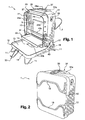
- a barbecue 1 according to the invention comprises a base 10 connected to a combustion chamber 20 comprising a front opening 23.
- the base 10 has a substantially rectangular shape with a circumferential edge 19 substantially transverse to the main plane of the base 10.
- the base 10 comprises four feet 11 ensuring the stability of the ground barbecue 1.
- These four legs 11 are formed by two curved round bars 18, preferably aluminum, each rotatable about an axis passing through the side flanks of the edge circumferential 19 of the base 10 from an unfolded position illustrated in FIG. figure 1 wherein the feet provide the ground stability of the barbecue 1, to a folded position illustrated in FIG. figure 2 wherein the two curved round bars 18 are each held in locations 12 formed in the thickness of the base 10 and forms complementary to the bending of the curved round bars 18.
- the base 10 is connected to the combustion chamber 20 via an axis 17 located at the end of two portions 16 projecting from the circumferential edge 19 of the base 10 and located near the bottom and back of the combustion chamber 20.
- this axis 17 allows the rotational movement of the base 10 relative to the combustion chamber 20 from a first position P1 said functional illustrated in FIG. figure 1 up to a second position P2 called transport illustrated at figure 2 .
- the combustion chamber 20 comprises two nesting parts, a main part 21 connected by the axis 17 to the base 10 and a removable part 22 whose size allows its insertion into the main part 21.
- a radiant gas burner 3 is disposed on the rear wall of the main part 21 of the combustion chamber 20 facing the front opening 23.
- the removable part 22 is held against the main part 21 on the one hand on its lower zone by a blade 25, arranged substantially transversely from the outside of the lower contour of the removable portion 22, being inserted into a series of grooves 15a, 15b of predetermined position disposed on a support block 14 fixed near the center of the base 10, and secondly on its upper zone by a curved round bar 26 removable, held by clipping in a groove among two grooves 28a, 28b formed on a first portion 37a of a multifunction block 37 disposed on the outer edge of the upper contour of the main portion 21 of the combustion chamber 20.
- the multifunction block 37 with all of these functions is described in more detail later in the text.
- the two ends of the curved round bar 26 each pass through a slot 27 formed on the outer edge of the upper contour of the removable portion 22 of the combustion chamber 20 and form a pivot connection by partially inserting into an orifice formed on a portion 29 protruding from the inner edge of the upper contour of the removable portion 22 of the combustion chamber 20.
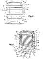
- the removable portion 22 of the combustion chamber 20 comprises on its side walls holding means 24 for food holding means 40 such as skewers 40a as illustrated in FIG. figure 5 or a grid 40b as shown in FIG. figure 6 .
- the skewers 40a have a square profile, nevertheless they may have another profile such as triangular to improve the rotational drive of the food on the skewer 40a.
- these retaining means 24 are constituted on a first of the two side walls of the removable part 22 by holes 24a for the passage of the end of the skewers 40a or slots 24b for the passage of retaining tabs 44 of the grid 40b and on the second of the two walls by slots 24b for the passage of the body of the skewers 40a or the retaining tabs 44 of the grid 40b.
- some retaining tabs 44 of the grid 40b have a protective sleeve 45 to prevent burns.
- the retaining means 24 also comprise a locking device 50 of the skewers in their slots 24b.
- this locking device 50 comprises a flat bar 51 of greater length than the distance separating the slot 24b being the lowest, the slot 24b being the highest on the second of the two side walls of the removable portion 22.
- This flat bar 51 is connected by a pivot connection 52 located below the slot 24b located lowest on the side wall of the removable portion 22 and slightly in front of the plane on which the skewers 40a are aligned when they are placed. in their respective holes 24a and slots 24b.
- the locking device 50 also comprises a series of notches 53 disposed on a side of the flat bar 51.
- the flat bar 51 is held in this position by means of a fastener 54 made by a removable butterfly screw or other locking device type lever or bolt.
- the skewers 40a are held in their slot 24b respectively with the aid of the flat bar 51 located nevertheless at a sufficient distance from the bottom of the slots 24b to not prevent the rotation of the skewers 40a.
- this locking device 50 also comprises a flat bar 51 of greater length than the distance separating the slot 24b being the lowest, the slot 24b being highest on the second of the two side walls of the removable portion 22.
- This flat bar 51 is slidably mounted in translation from a low position to a high position.
- This flat bar 51 is achieved by the arrangement at both ends of the flat bar 51 of two oblong holes 55 oriented vertically in which slide an axis 56 fixed at a predetermined position to the inner side wall of the removable portion 22.
- the amplitude of the translational movement of the flat bar 51 is defined by the length of the oblong holes 55 serving as a stop for the two axes 56.
- the flat bar 51 is by default in the low position.
- the upper end of the flat bar 51 passes through the wall of the removable part 22 via an opening 57 formed in the extension of the flat bar 51.
- the flat bar 51 comprises on its projecting portion of the removable portion, a gripping means 59 made for example by the curved end of the flat bar 51.
- the locking device 50 also comprises a series of hooks 58 oriented downwards and projecting from the side of the flat bar 51 coinciding with the slots 24b when the flat bar 51 is in its low position and releasing the slots 24b when the bar flat is in its high position.
- the skewers 40a are held in their respective slot 24b using the hooks 58 of the flat bar 51 located nevertheless at a sufficient distance from the bottom of the slots 24b to not prevent the rotation of the skewers 40a.
- this blocking device 50 uses specific skewers 40a provided with a device 90 with retractable pinion 41.
- the handle 43 of the skewer 40a comprises a body 91 in which is formed an annular groove 92 inserted into the slot 24b in which is inserted the skewer 40a.
- This annular groove 92 includes an inner annular shoulder 92a located on the inner side of the removable portion 22 of the combustion chamber 20 and an annular shoulder 92b on the outer side of the removable portion 22 of the combustion chamber 20.
- the body 93 of the pinion 41 is slidably mounted by being supported on the one hand inside the throat ring 92 formed in the body 91 of the handle 43 via a shoulder 93a, and secondly on a guide portion 94 of the body 91 of the handle 43.
- the shoulder 93a is substantially the same height as the depth of the annular groove 92.
- This cylindrical chamber 97 comprises a helical spring 98 in compression bearing on the one hand on the side of the shoulder 93a of the body 93 of the pinion 41 and on the other hand on the outer shoulder 92b of the annular groove 92 formed in the body 91 of the handle 43.
- the length of the spring 98 is determined so as to maintain a permanent clearance between the wall of the removable part 22 of the combustion chamber 20 located near the slot 24b in which the skewer 40a is inserted and on the one hand the inner shoulder 92a of the body 91 of the handle 43 and secondly an annular shoulder 93b of the body 93 of the pinion 41 located between the wall of the removable portion 22 and the pinion 41.
- This annular shoulder 93b has a diameter greater than the width of the slot 24b and preferably smaller than the diameter of the pinion 41.
- the body 93 of the pinion 41 on its end farthest from the wall of the removable portion 22 of the combustion chamber 20 also comprises another annular shoulder 95 intended to provide an annular spacing 96 around the body 93 of the pinion 41 for the passage fingers of the user.
- the locking device 50 comprises an abutment 99 projecting from the outer surface of the wall of the removable part 22 of the combustion chamber 20.
- This stop 99 is placed close to the slot 24b at a distance from the axis of rotation of the skewer 40a slightly greater than the diameter of the shoulder 93b of the body 93 of the pinion 41.
- this stop 99 is greater than the total clearance created between the inner annular shoulder 92a and the annular shoulder 93b of the body 93. pinion 41 when the coil spring 98 in compression is in the rest position.
- this stop 99 is placed on the side of the slot 24b meeting first a predetermined portion of the pinion 41.
- the stop is placed on the upper side of the slot 24b. It is placed on the lower side when the pinion 41 moves in the anti-trigonometric direction.
- the user is supported with his hand on the handle 43 of the skewer 40a and inserting its fingers in the spacing 96 by bearing on the shoulder 95 of the body 93 of the pinion 41.
- the skewers 40a which normally tend to come out of their respective slot 24b, are then held in it by the action of the stop 99 on which abuts and slides the annular shoulder 93b of the body 93 of the pinion 41.
- the body 93 of the pinion further comprises the third embodiment presented above, an annular shoulder 101 centered on the annular shoulder 93b.
- This annular shoulder 101 has a width greater than the thickness of the wall of the removable part 22 so that in the locking position shown in FIG. figure 12 this annular shoulder 101 abuts against the annular shoulder 92a under the action of the spring 98.
- the latter In this locking position, and in order to center the annular shoulder 101 on the inner annular shoulder 92a, the latter can have an annular groove 103 in which is inserted the end of the annular shoulder 101.
- the slots 24b comprise a circular hole-shaped termination 102 centered on the axis of rotation of the skewers 40a and of the same diameter with the clearance of the diameter of the annular shoulder 101.
- This circular hole 102 replaces the stop 99 presented in the third embodiment while performing the same stop function.
- the sliding function of the annular shoulder 93b during the rotation of the skewers 40a in the third embodiment is provided by the annular shoulder 101 which abuts and slides against the edges of the circular hole 102 formed in the slots 24b in this embodiment. fourth embodiment.
- the dimensioning of the spring 98 is less important than in the third embodiment because the annular shoulder 101 abuts the annular shoulder 92a and the fact that a permanent gap is held between the annular shoulder 93b and the inner annular shoulder 92a defined by the width of the annular shoulder 101.
- This difference is greater than the thickness of the wall of the removable part and makes it possible to give the necessary clearance to the rotational movement of the skewers 40a in the slots 24b.
- the user rests with his hand on the handle 43 of the skewer 40a and inserts his fingers in the spacing 96 by bearing on the shoulder 95 of the body 93 of the pinion 41.
- the skewers 40a which normally tend to come out of their respective slot 24b, are then held in it by the action of the edge of the circular hole 102 on which abuts and slides the annular shoulder 101 of the body 93 of the pinion. 41.
- the fact of being able to block the skewers 40a and even the double grid 40b for certain blocking devices 50 allows the user to prepare, remotely from the barbecue 1, the arrangement of the food holding means 40 on the removable part. 22 arranged for example horizontally on a flat surface, then allows the user to move vertically removable part 22 by grasping its curved round bar 26 without risk of falling to the holding means 40 food.
- a drive means embodied by a pinion 41 disposed transversely to the body of the skewer 40a and a handle 43 extending this end of the skewer 40a.
- the second end of the skewer 40a is inserted into a hole 24a or through a slot 24b on the first of the two side walls of the removable part 22 so that the pinion 41 of the skewer 40a remains adjacent to the surface. exterior of the second of the two side walls of the removable portion 22.
- the diameter of the pinions, the size of the teeth of the pinions and the spacing between two adjacent retaining means 24 is predetermined so that the arrangement of the set of skewers forms a gearing 42 allowing the driving in rotation of a adjacent kebab.
- the rotational drive of the central skewer 40a in an embodiment comprising for example five skewers 40a, such as the one shown in FIGS. figures 4 and 5 will cause rotation at the same speed of the two adjacent skewers 40a which will in turn rotate the two skewers 40a end.
- This rotation can be performed manually using a removable crank (not shown) or with a commercially available removable battery electric motor 6, as shown in FIG. figure 5 , attaching to the outer surface of the first of the two side walls of the removable portion 22 by means of a removable support device 60 illustrated in FIGS. Figures 10 and 11 and detailed below.
- the electric motor 6 comprises, in a known manner, a square profile off-axis drive shaft and a stop located at an adjustment distance from said drive shaft whose function is to prevent the rotation of the electric motor 6 with respect to the side wall of the barbecue. 1.
- This support device 60 comprises two parts 61, 62 connected to each other.
- the first part 61 has the function of positioning the support device 60 with respect to the lateral wall of the removable part 22.
- the second part has the function of positioning the electric motor 6 relative to the first part 61.
- the first portion 61 comprises an elastic clip 63 composed of three tabs 64a, 64b and 64c.
- the tabs 64a, 64b and 64c are engaged on the side wall of the removable part 22.
- the tabs 64a and 64b are then found on the outer side of the side wall of the removable part 22 while the tab 64c is found on the inner side of the same side wall and is guided by means of two rails 65 arranged in a fixed manner on either side of the central hole 24a of the retaining means of the central skewer 40a.
- the tab 64c comprises an orifice 71 coinciding with the hole 24a of the retaining means 24 of the central skewer 40a formed on the side wall of the removable part 22.
- each of the tabs 64a, 64, b and 64c is slightly curved to facilitate their insertion on the sidewall flank of the removable portion 22 and to have legs 64a, 64b and 64c having a high stiffness allowing a solid support of the support device 60 on the side wall of the removable part 22.
- the second portion 62 has a U-shaped base 66 whose ends of the legs are welded to the clips 64a and 64b to move the base 66 away from the side wall of the removable portion 22.
- a hollow hub 67 free to rotate about an axis corresponding to the axis of the central skewer 40a once it is disposed at its location on its retaining means 24.
- This hollow hub 67 is held by two circlips arranged on either side of the base 66 and inserted into transverse annular grooves formed in the hollow hub 67.
- the hollow hub 67 has at its center a square hollow tube 68 projecting transversely in the direction opposite to the combustion chamber 20.
- This square tube 68 has dimensions slightly greater than the square profile of the end of a skewer 40a and slightly smaller than the off-axis axis of square profile of the electric motor 6.
- the plate 69 comprises a passage 70 in the form of a keyhole with a circular portion 70a of large diameter and an oblong portion 70b of width less than the diameter of the circular portion 70a.
- the circular portion is aligned coaxially with the hole 24a formed in the side wall of the removable portion 22 for holding the skewer 40a immediately above the central skewer 40a.
- the oblong portion 70b is disposed below the circular portion 70a.
- the user To use the motorized rotation of the skewers 40a, the user first grasps the support device 60 of the electric motor 6 on which he inserts the off-axis square drive shaft of the electric motor 6 into the square tube 68 and its stopping by the circular portion 70a.
- the skewers 40a comprise a ring of circular section with two lateral flanges between which are inserted the notches 53 or the hooks 58 according to the embodiment used.
- the barbecue 1 provides a preparation zone and / or storage 13 after cooking two additional skewers 40a.
- a removable grease recovery tray 30 held by rails 31 arranged on the inner wall of the removable part 22.
- These rails 31 allow a horizontal translational movement of the removable tray 30 to allow the release for a possible wash for example.
- the multifunctional block 37 is integrally formed in one piece, preferably made of hard plastic molded resistant to high temperatures and comprises the first portion 37a disposed on the outer edge of the upper contour of the main portion 21 of the combustion chamber 20 and a second portion 37b substantially disposed transversely to the first portion 37a and covering an entire upper portion of the rear of the main portion 21 of the combustion chamber 20.
- This multifunction block 37 is preferably held by clipping against the main part 21 of the combustion chamber 20 preferably made of sheet metal, but it is obvious to the skilled person that it can be fixed to the main part 21 of the combustion chamber 20 by any other equivalent means, for example screws.
- the second portion 37b of the multifunction block 37 also comprises a handle 9 molded in the multifunction block allowing a user to move the barbecue 1 whether it is in transport position P2 or in the operating position P1.
- the second portion 37b of the multifunction block 37 comprises a hole for the passage of a flexible gas supply pipe 7 connecting the radiant burner 3 to a gas expander 4 and a compartment 5 molded with the multifunction block 37 used to store the gas regulator 4 when it is not connected to a cylinder or a gas cartridge 2.
- the gas expander 4 comprises a connecting device performing the dual function of pressure reducer and valve and easily connecting to a gas cartridge 2 in the manner described in the patent EP0981005 or the patent application EP1802908 .
- This attachment means 32 may for example be made by a dovetail or by the arrangement of a rail disposed on the second portion 37b of the multifunction block 37 and a slide shape complementary to that of the rail arranged on the gas regulator 4 or vice versa.
- attachment means 32 are also present in the compartment 5 in order to hold during transport the gas expander 4 when it is not connected to a gas cartridge 2.
- the gas cartridge 2 comes into contact with a profiled surface 80 located at the rear of the combustion chamber 20 shown in FIG. figure 4 by the AA view on the back of the barbecue 1.
- This profiled surface 80 reduces the cooling of the gas cartridge 2 during the release of the gas contained in the expander 4 or at low outside temperatures by heating more radiation, conduction but also by convection the gas cartridge 2 through the radiant burner 3 located nearby.
- a locking means 34 blocking the barbecue 1 in its functional position P1, thus preventing an inadvertent folding of the barbecue 1 to its transport position P2.
- this locking means 34 may for example comprise a spring button connected to a lamella bearing on the main part 21 of the combustion chamber 20 when the barbecue is in its operative position P1.
- the barbecue 1 also comprises a locking means 33 blocking the barbecue 1 in its transport position P2, thus preventing an inadvertent deployment of the barbecue 1 to its operating position P1.
- This locking means 33 is formed by an elastic hook connected to the outer front edge of the edge 19 of the base 10 by a free end of rotation around the attachment points to the base 10, while the other end is snapped into the groove 28b formed on the first portion 37a of the multifunction block 37.
- transport rings 35 are also provided arranged on the upper zone of the outside of the side walls of the main part 21 of the combustion chamber 20, as well as a removable strap 36 coming in a known manner to hook the two rings of transport 35.
- the user of the barbecue 1 can thus carry the barbecue 1 on one of these shoulders.
- This indication can be visual or simply sound.
- the removable part 22 of the combustion chamber 20 is recessed inside the main part 21 and the skewers 40a are arranged diagonally of the removable part 22.
- the user therefore starts by removing the removable part 22, the grease trap 30, the skewers 40a, which it can for example have on the preparation zone and / or storage 13, as well as possibly the removable electric motor. 6 and its support device 60.
- the curved round bar 26 of the removable part 22 is optionally retained by an elastic tab (not shown) disposed inside the main part 21 of the combustion chamber 20 to prevent the rounded bar bar 26 from moving and n 'generates noise when transporting the barbecue 1.
- the removable portion 22 is placed flat on a flat surface.
- the user After having prepared the skewers 40a or the double grid 40b by hanging food, the user places them on the retaining means 24 by first inserting the end of the skewers 40a in the holes 24a and then bringing the body skewers 40a in the slots 24b, taking care to align the set of pinions 41 skewers 40a to form the gear 42.
- the center skewer 40a of square profile is thus inserted into the square profile drive shaft of the electric motor 6.
- the removable part 22 In order to position the removable part 22 on the barbecue 1, it grasps the bottom of the removable part and places the blade 25 inside one of the series of grooves 15a, 15b of the support block 14 and hangs the curved round bar 26 on the appropriate groove among the grooves 28a, 28b formed on a first portion 37a of the multifunction block 37 to stabilize the removable portion 22 of the combustion chamber 20.
- the fat of the food is then recovered in the recovery tank 30 provided for this purpose.
- the user closes the gas supply using the valve on the gas regulator 2 and stops the rotation of the skewers 40a by stopping the electric motor 6.
- the gas cartridge 2 can remain attached to the barbecue 1 without this being inconvenient to transport.
- this compact barbecue 1 makes this barbecue 1 a device easy to use and carry with a small footprint.
- the height of the feet 11 positions the base 10 at 5 cm from the ground for a total height of less than 45 cm, a depth of less than 43 cm. cm and a width less than 35 cm.
Landscapes
- Engineering & Computer Science (AREA)
- Food Science & Technology (AREA)
- Baking, Grill, Roasting (AREA)
Claims (13)
- Kompakter Grill (1), der mit einer Gasflasche oder einer Gaspatrone (2) verbunden werden kann, und zum Garen von Nahrungsmitteln bestimmt ist und folgendes umfasst:- ein Basisgestell (10),- eine Brennkammer (20), die mit dem Basisgestell (10) verbunden ist, und eine vordere Öffnung (23) umfasst,- einen Gasstrahlungsbrenner (3), der im Inneren der Brennkammer (20), auf Höhe der vorderen Öffnung (23) derselben angeordnet ist,
wobei sich der Grill (1) zusammenklappen lässt, da das Basisgestell (10) im Verhältnis zur Brennkammer (20) ausgehend von einer ersten Stellung (P1), die Betriebsstellung genannt wird, in der:- das Basisgestell (10) in etwa quer zur Brennkammer (20) angeordnet ist, und für die Stabilität des Grills (1) auf dem Boden sorgt, und- die vordere Öffnung (23) der Brennkammer (20) nach außen offen ist, in eine zweite Stellung (P2) bewegt werden kann, die Transportstellung genannt wird, und in der:- das Basisgestell (10) in etwa längs zur Brennkammer (20) angeordnet ist und die Öffnung (23) der Brennkammer (20) abdeckt, und
die Brennkammer (20) Haltemittel (24) umfasst, die sich nahe der vorderen Öffnung (23) befinden, und angeordnet sind, um die abnehmbaren Halteeinrichtungen (40) für die zu garenden Nahrungsmittel gegenüber dem Gasstrahlungsbrenner (3) zu halten, wenn sich der Grill (1) in seiner Betriebsstellung (P1) befindet,
wobei die Brennkammer (20) einen abnehmbaren Abschnitt (22) umfasst, und der abnehmbare Abschnitt eine Vorrichtung (50) zum Festhalten der Halteeinrichtungen (40) umfasst. - Grill (1) nach Anspruch 1, bei dem die Festhaltevorrichtung (50) für die Halteeinrichtungen (40) eine längliche Vorrichtung (51) umfasst, die aus einer ersten Stellung, in der das Herausnehmen der Halteeinrichtungen (40) aus ihren Haltemitteln (24) unterbunden wird, in eine zweite Stellung bewegt werden kann, in der das Herausnehmen der Halteeinrichtungen (40) aus ihren Haltemitteln (24) zulässig ist.
- Grill (1) nach Anspruch 1, bei dem die Festhaltevorrichtung (50) der Halteeinrichtungen (40) eine Vorrichtung (90) umfasst, die von den Halteeinrichtungen (40) getragen wird, und einen Ansatz (93a, 101) umfasst, der aus einer ersten Stellung, in der der Ansatz (93a, 101) das Herausnehmen der Halteeinrichtungen (40) aus ihren Haltemitteln (24) unterbindet, indem er mit den Stoppvorrichtungen (99, 102) zusammenwirkt, in eine zweite Stellung verschoben werden kann, in der der Ansatz (93a, 101) von den Stoppvorrichtungen (99, 102) abgehoben ist, und das Herausnehmen der Halteeinrichtungen (40) aus ihren Haltemitteln (24) zulässt.
- Grill (1) nach Anspruch 3, bei dem die Stoppvorrichtungen einen Anschlag (99) umfassen, der an einer Wand des abnehmbaren Abschnitts (22) angeordnet ist.
- Grill (1) nach Anspruch 3, bei dem die Stoppvorrichtungen ein kreisrundes Loch (102) in einer Form umfassen, die ergänzend zu einem kreisrunden Abschnitt des Ansatzes (101) ist.
- Grill (1) nach einem der Ansprüche 1 bis 5, bei dem die Stellung des abnehmbaren Abschnitts (22), sobald dieser auf dem Grill (1) montiert ist, aus einer ersten vorbestimmten Stellung, die angenäherte Stellung genannt wird, und in der der abnehmbare Abschnitt (22) relativ nahe am Gasbrenner (3) steht, und zumindest einer zweiten vorbestimmten Stellung, die entfernte Stellung genannt wird, und in der der abnehmbare Abschnitt (22) im Vergleich zur angenäherten Stellung relativ weit vom Gasbrenner (3) entfernt steht, ausgewählt wird.
- Grill (1) nach einem der Ansprüche 1 bis 6, bei dem die abnehmbaren Halteeinrichtungen (40) Spieße (40a) sind, die innerhalb der Haltemittel (24) in Drehung versetzt werden können, und jeweils eine Antriebsvorrichtung (41), wie ein Ritzel, enthalten, die ein Räderwerk (42) mit dem (den) benachbarten Spieß(en) (40a) ergeben, um die Drehbewegung aufeinander zu übertragen.
- Grill (1) nach einem der vorherigen Ansprüche, der eine profilierte Oberfläche (80) mit der Kontur der Gaspatrone (2) umfasst, die sich an der Rückseite der Brennkammer (20) befindet, die sich in der entgegengesetzten Richtung zu ihrer vorderen Öffnung (23) befindet.
- Grill (1) nach einem der vorherigen Ansprüche, bei dem die Brennkammer (20) an ihrer Rückseite, die sich in der entgegengesetzten Richtung zu ihrer vorderen Öffnung (23) befindet, ein Ablagefach (5) für einen Gasdruckregler (4) umfasst, das dazu bestimmt ist, darin den Gasdruckregler (4) abzulegen, wenn dieser nicht an der Gasflasche oder der Gaspatrone (2) angeschlossen ist.
- Grill (1) nach einem der vorherigen Ansprüche, der Befestigungsvorrichtungen (32) umfasst, die angeordnet sind, um einen Gasdruckregler (4) an der Rückseite der Brennkammer (20) zu halten, die sich in der entgegengesetzten Richtung zu ihrer vorderen Öffnung (23) befindet.
- Grill (1) nach einem der vorherigen Ansprüche, der eine Verriegelungsvorrichtung (34) umfasst, anhand derer der Grill (1) in seiner Betriebsstellung (P1) gehalten werden kann.
- Grill (1) nach einem der vorherigen Ansprüche, bei dem das Basisgestell (10) eine Zone zur Zubereitung (13) und/ oder zur Ablage umfasst, wenn sich der Grill (1) in seiner Betriebsstellung (P1) befindet.
- Grill (1) nach einem der vorherigen Ansprüche, bei dem die Brennkammer (20) an ihrer Rückseite, die sich in der entgegengesetzten Richtung zu ihrer vorderen Öffnung (23) befindet, einen Transportgriff (9) umfasst, mit dem der Grill (1) in seiner Transportstellung (P2) aber auch in seiner Betriebsstellung (P1) bewegt werden kann.
Applications Claiming Priority (2)
| Application Number | Priority Date | Filing Date | Title |
|---|---|---|---|
| FR1055273A FR2962022B1 (fr) | 2010-07-01 | 2010-07-01 | Barbecue compact |
| PCT/FR2011/051402 WO2012001264A1 (fr) | 2010-07-01 | 2011-06-20 | Barbecue compact |
Publications (2)
| Publication Number | Publication Date |
|---|---|
| EP2587974A1 EP2587974A1 (de) | 2013-05-08 |
| EP2587974B1 true EP2587974B1 (de) | 2014-10-29 |
Family
ID=43532858
Family Applications (1)
| Application Number | Title | Priority Date | Filing Date |
|---|---|---|---|
| EP11737989.1A Not-in-force EP2587974B1 (de) | 2010-07-01 | 2011-06-20 | Kompakter grill |
Country Status (7)
| Country | Link |
|---|---|
| US (1) | US20130167738A1 (de) |
| EP (1) | EP2587974B1 (de) |
| JP (1) | JP2013529529A (de) |
| CA (1) | CA2803494A1 (de) |
| FR (1) | FR2962022B1 (de) |
| RU (1) | RU2553200C2 (de) |
| WO (1) | WO2012001264A1 (de) |
Families Citing this family (5)
| Publication number | Priority date | Publication date | Assignee | Title |
|---|---|---|---|---|
| AU2014200512B2 (en) * | 2014-01-30 | 2015-10-29 | Shaker Azzam | Cooking apparatus |
| KR101738891B1 (ko) * | 2015-10-30 | 2017-05-23 | (주)월드코리아 | 가스 직화 구이기 |
| NL2017404B1 (nl) * | 2016-09-01 | 2018-03-09 | Mohammad Charif Soubra | Portable Barbecue |
| RU203575U1 (ru) * | 2020-10-12 | 2021-04-12 | Автономная некоммерческая организация высшего образования «Белгородский университет кооперации, экономики и права» | Гриль |
| DE202023106348U1 (de) * | 2023-10-31 | 2023-11-29 | Vennskap Gmbh & Co. Kg | Mobiler Gaskocher |
Family Cites Families (29)
| Publication number | Priority date | Publication date | Assignee | Title |
|---|---|---|---|---|
| US2511594A (en) * | 1945-07-06 | 1950-06-13 | Loffredo Peter | Barbecue grill |
| US2515521A (en) * | 1946-10-30 | 1950-07-18 | Loffredo Peter | Camper's stove |
| US2742893A (en) * | 1951-01-26 | 1956-04-24 | Vern L Keffer | Portable cooking stove |
| US3438364A (en) * | 1966-05-16 | 1969-04-15 | Louie A Galloway Jr | Barbecue grill and the like |
| GB1424399A (en) * | 1972-07-06 | 1976-02-11 | Etud Sa | Portable cooking appliance |
| US4089258A (en) * | 1975-08-29 | 1978-05-16 | Ducane Heating Corporation | Gas fired barbecue unit |
| US3991666A (en) * | 1975-11-06 | 1976-11-16 | Tidwell William F | Portable cooking unit |
| US4524751A (en) * | 1982-08-20 | 1985-06-25 | Hoglund Allen C | Portable cooking device |
| US5105726A (en) * | 1990-08-09 | 1992-04-21 | Mikhail Lisker | Portable universal cooking grill |
| US5158067A (en) * | 1991-10-21 | 1992-10-27 | Dutro Company | Wok adapted portable food cooker |
| US5237912A (en) * | 1992-07-29 | 1993-08-24 | Todd Fins | Heating and cooking apparatus |
| US5605142A (en) * | 1994-04-04 | 1997-02-25 | Parker, Inc. | Portable barbeque |
| US5575195A (en) * | 1996-01-16 | 1996-11-19 | Foxford; Kenneth E. | Collapsible portable cooking unit |
| US5906196A (en) * | 1997-02-24 | 1999-05-25 | Dutro Company | Portable stove with self-stored legs |
| US5782168A (en) * | 1997-08-05 | 1998-07-21 | Krhnak; Peter S. | Portable grill |
| FR2782365B1 (fr) | 1998-08-14 | 2000-10-06 | Applic Gaz Sa | Dispositif d'accouplement d'un appareil sur une cartouche de fluide sous pression |
| US6167797B1 (en) * | 1999-07-01 | 2001-01-02 | Gerald Bollich | Portable commercial barbecue cooker |
| US6102027A (en) * | 1999-10-26 | 2000-08-15 | Tilby; Nolan C. | Collapsible and portable outdoor cooking stove assembly |
| US6725856B1 (en) * | 2002-02-25 | 2004-04-27 | Barbour International, Inc. | Outdoor gas cook stove with knockdown legs |
| US20040081932A1 (en) * | 2002-10-23 | 2004-04-29 | Sen-Yu Wu | Ignition device for a grill |
| US20050115556A1 (en) * | 2003-12-01 | 2005-06-02 | Kenneth Carson | Turkey fryer/outdoor cooker wind and fire guard |
| USD514871S1 (en) * | 2004-04-30 | 2006-02-14 | The Brinkman Corporation | Portable stove |
| FR2876776B1 (fr) | 2004-10-19 | 2007-01-19 | Applic Des Gaz Soc Par Actions | Dispositif de connexion d'appareil a gaz et cartouche de gaz |
| KR100642006B1 (ko) * | 2005-02-18 | 2006-11-13 | 주식회사 웰바스 | 냉각 시스템을 갖춘 바비큐 그릴 |
| US20070012201A1 (en) * | 2005-07-12 | 2007-01-18 | Wei-Teh Ho | Hotdog cooker |
| RU54500U1 (ru) * | 2006-02-13 | 2006-07-10 | Сергей Николаевич Новосельцев | Устройство для приготовления пищи на открытом огне |
| US7591220B2 (en) * | 2006-06-13 | 2009-09-22 | Sheridan Jr James T | Portable roller grill |
| CN101522082A (zh) * | 2006-08-01 | 2009-09-02 | 尼尔·A·艾伦 | 食物架 |
| US8297271B2 (en) * | 2008-10-07 | 2012-10-30 | Biolite Llc | Portable combustion device utilizing thermoelectrical generation |
-
2010
- 2010-07-01 FR FR1055273A patent/FR2962022B1/fr not_active Expired - Fee Related
-
2011
- 2011-06-20 WO PCT/FR2011/051402 patent/WO2012001264A1/fr not_active Ceased
- 2011-06-20 CA CA2803494A patent/CA2803494A1/fr not_active Abandoned
- 2011-06-20 US US13/806,858 patent/US20130167738A1/en not_active Abandoned
- 2011-06-20 JP JP2013517437A patent/JP2013529529A/ja not_active Withdrawn
- 2011-06-20 RU RU2013103497/12A patent/RU2553200C2/ru not_active IP Right Cessation
- 2011-06-20 EP EP11737989.1A patent/EP2587974B1/de not_active Not-in-force
Also Published As
| Publication number | Publication date |
|---|---|
| FR2962022A1 (fr) | 2012-01-06 |
| FR2962022B1 (fr) | 2012-07-27 |
| US20130167738A1 (en) | 2013-07-04 |
| JP2013529529A (ja) | 2013-07-22 |
| WO2012001264A1 (fr) | 2012-01-05 |
| CA2803494A1 (fr) | 2012-01-05 |
| RU2013103497A (ru) | 2014-08-10 |
| RU2553200C2 (ru) | 2015-06-10 |
| EP2587974A1 (de) | 2013-05-08 |
Similar Documents
| Publication | Publication Date | Title |
|---|---|---|
| EP2587974B1 (de) | Kompakter grill | |
| EP3100655B1 (de) | Schnellkochtopf mit bajonettverschluss, der mit führungselementen ausgestattet ist | |
| CA2621216C (fr) | Capot de nacelle pour turboreacteur et nacelle comportant au moins un tel capot | |
| EP1871205B1 (de) | Sicherheitsgrill mit doppelter vertikaler feuerkammer | |
| FR2924574A1 (fr) | Moule pour realiser un aliment a base d'une pate se gonflant sous la chaleur | |
| FR3003149A1 (fr) | Appareil de cuisson comprenant au moins deux panneaux amovibles | |
| FR3034972A3 (fr) | Kit de gril | |
| FR2929079A1 (fr) | Machine portative destinee a la fabrication de brochettes | |
| EP2445381B1 (de) | Kochvorrichtung | |
| EP2606788B1 (de) | Doppelseitiges Kochgerät mit entriegelbarer Verriegelung | |
| EP2978347B1 (de) | Ofen | |
| FR2922091A1 (fr) | Appareil de cuisson de type barbecue a grilles multiples | |
| FR2953389A1 (fr) | Dispositif pour le reglage de la distance entre le support de cuisson et la source de chaleur d'un appareil de cuisson | |
| EP2606787A1 (de) | Doppelseitiges Kochgerät mit thermisch geschützten Heizplatten | |
| EP3079544B1 (de) | Haushaltsgerät zur lebensmittelzubereitung mit einem unterem arm an einem sockel und einem oberem arm, der über scharniere mit dem unteren arm verbunden ist | |
| EP0612476A1 (de) | Vorrichtung zur Herstellung von Sandwichs (belegten Broten) | |
| EP0792608B1 (de) | Scharnier für Elektrokochplatten und Kochgerät mit Scharnier | |
| FR3080527A1 (fr) | Barbecue a foyers verticaux et enceinte de cuisson a parois | |
| EP1152681B1 (de) | Verfahren zum heben und senken eines fritierkorbes | |
| FR2812529A1 (fr) | Gril au charbon de bois | |
| FR2722966A1 (fr) | Dispositif de cuisson pour brochettes | |
| FR2819581A1 (fr) | Dispositif de support et de positionnement d'un bruleur a gaz dans un appareil de cuisson | |
| WO2002028190A1 (fr) | Procede et machine pour garnir des sandwichs | |
| FR2960410A1 (fr) | Grille-pain electrique | |
| EP1604597B1 (de) | Brotroster |
Legal Events
| Date | Code | Title | Description |
|---|---|---|---|
| PUAI | Public reference made under article 153(3) epc to a published international application that has entered the european phase |
Free format text: ORIGINAL CODE: 0009012 |
|
| 17P | Request for examination filed |
Effective date: 20121115 |
|
| AK | Designated contracting states |
Kind code of ref document: A1 Designated state(s): AL AT BE BG CH CY CZ DE DK EE ES FI FR GB GR HR HU IE IS IT LI LT LU LV MC MK MT NL NO PL PT RO RS SE SI SK SM TR |
|
| DAX | Request for extension of the european patent (deleted) | ||
| 17Q | First examination report despatched |
Effective date: 20131024 |
|
| GRAP | Despatch of communication of intention to grant a patent |
Free format text: ORIGINAL CODE: EPIDOSNIGR1 |
|
| INTG | Intention to grant announced |
Effective date: 20140606 |
|
| GRAS | Grant fee paid |
Free format text: ORIGINAL CODE: EPIDOSNIGR3 |
|
| GRAA | (expected) grant |
Free format text: ORIGINAL CODE: 0009210 |
|
| AK | Designated contracting states |
Kind code of ref document: B1 Designated state(s): AL AT BE BG CH CY CZ DE DK EE ES FI FR GB GR HR HU IE IS IT LI LT LU LV MC MK MT NL NO PL PT RO RS SE SI SK SM TR |
|
| REG | Reference to a national code |
Ref country code: GB Ref legal event code: FG4D Free format text: NOT ENGLISH |
|
| REG | Reference to a national code |
Ref country code: CH Ref legal event code: EP |
|
| REG | Reference to a national code |
Ref country code: AT Ref legal event code: REF Ref document number: 693149 Country of ref document: AT Kind code of ref document: T Effective date: 20141115 |
|
| REG | Reference to a national code |
Ref country code: IE Ref legal event code: FG4D Free format text: LANGUAGE OF EP DOCUMENT: FRENCH |
|
| REG | Reference to a national code |
Ref country code: DE Ref legal event code: R096 Ref document number: 602011010961 Country of ref document: DE Effective date: 20141211 |
|
| REG | Reference to a national code |
Ref country code: AT Ref legal event code: MK05 Ref document number: 693149 Country of ref document: AT Kind code of ref document: T Effective date: 20141029 |
|
| REG | Reference to a national code |
Ref country code: NL Ref legal event code: VDEP Effective date: 20141029 |
|
| REG | Reference to a national code |
Ref country code: LT Ref legal event code: MG4D |
|
| PG25 | Lapsed in a contracting state [announced via postgrant information from national office to epo] |
Ref country code: PT Free format text: LAPSE BECAUSE OF FAILURE TO SUBMIT A TRANSLATION OF THE DESCRIPTION OR TO PAY THE FEE WITHIN THE PRESCRIBED TIME-LIMIT Effective date: 20150302 Ref country code: ES Free format text: LAPSE BECAUSE OF FAILURE TO SUBMIT A TRANSLATION OF THE DESCRIPTION OR TO PAY THE FEE WITHIN THE PRESCRIBED TIME-LIMIT Effective date: 20141029 Ref country code: NL Free format text: LAPSE BECAUSE OF FAILURE TO SUBMIT A TRANSLATION OF THE DESCRIPTION OR TO PAY THE FEE WITHIN THE PRESCRIBED TIME-LIMIT Effective date: 20141029 Ref country code: NO Free format text: LAPSE BECAUSE OF FAILURE TO SUBMIT A TRANSLATION OF THE DESCRIPTION OR TO PAY THE FEE WITHIN THE PRESCRIBED TIME-LIMIT Effective date: 20150129 Ref country code: LT Free format text: LAPSE BECAUSE OF FAILURE TO SUBMIT A TRANSLATION OF THE DESCRIPTION OR TO PAY THE FEE WITHIN THE PRESCRIBED TIME-LIMIT Effective date: 20141029 Ref country code: IS Free format text: LAPSE BECAUSE OF FAILURE TO SUBMIT A TRANSLATION OF THE DESCRIPTION OR TO PAY THE FEE WITHIN THE PRESCRIBED TIME-LIMIT Effective date: 20150228 Ref country code: FI Free format text: LAPSE BECAUSE OF FAILURE TO SUBMIT A TRANSLATION OF THE DESCRIPTION OR TO PAY THE FEE WITHIN THE PRESCRIBED TIME-LIMIT Effective date: 20141029 |
|
| PG25 | Lapsed in a contracting state [announced via postgrant information from national office to epo] |
Ref country code: GR Free format text: LAPSE BECAUSE OF FAILURE TO SUBMIT A TRANSLATION OF THE DESCRIPTION OR TO PAY THE FEE WITHIN THE PRESCRIBED TIME-LIMIT Effective date: 20150130 Ref country code: HR Free format text: LAPSE BECAUSE OF FAILURE TO SUBMIT A TRANSLATION OF THE DESCRIPTION OR TO PAY THE FEE WITHIN THE PRESCRIBED TIME-LIMIT Effective date: 20141029 Ref country code: RS Free format text: LAPSE BECAUSE OF FAILURE TO SUBMIT A TRANSLATION OF THE DESCRIPTION OR TO PAY THE FEE WITHIN THE PRESCRIBED TIME-LIMIT Effective date: 20141029 Ref country code: SE Free format text: LAPSE BECAUSE OF FAILURE TO SUBMIT A TRANSLATION OF THE DESCRIPTION OR TO PAY THE FEE WITHIN THE PRESCRIBED TIME-LIMIT Effective date: 20141029 Ref country code: CY Free format text: LAPSE BECAUSE OF FAILURE TO SUBMIT A TRANSLATION OF THE DESCRIPTION OR TO PAY THE FEE WITHIN THE PRESCRIBED TIME-LIMIT Effective date: 20141029 Ref country code: LV Free format text: LAPSE BECAUSE OF FAILURE TO SUBMIT A TRANSLATION OF THE DESCRIPTION OR TO PAY THE FEE WITHIN THE PRESCRIBED TIME-LIMIT Effective date: 20141029 Ref country code: PL Free format text: LAPSE BECAUSE OF FAILURE TO SUBMIT A TRANSLATION OF THE DESCRIPTION OR TO PAY THE FEE WITHIN THE PRESCRIBED TIME-LIMIT Effective date: 20141029 Ref country code: AT Free format text: LAPSE BECAUSE OF FAILURE TO SUBMIT A TRANSLATION OF THE DESCRIPTION OR TO PAY THE FEE WITHIN THE PRESCRIBED TIME-LIMIT Effective date: 20141029 |
|
| REG | Reference to a national code |
Ref country code: DE Ref legal event code: R097 Ref document number: 602011010961 Country of ref document: DE |
|
| PG25 | Lapsed in a contracting state [announced via postgrant information from national office to epo] |
Ref country code: SK Free format text: LAPSE BECAUSE OF FAILURE TO SUBMIT A TRANSLATION OF THE DESCRIPTION OR TO PAY THE FEE WITHIN THE PRESCRIBED TIME-LIMIT Effective date: 20141029 Ref country code: CZ Free format text: LAPSE BECAUSE OF FAILURE TO SUBMIT A TRANSLATION OF THE DESCRIPTION OR TO PAY THE FEE WITHIN THE PRESCRIBED TIME-LIMIT Effective date: 20141029 Ref country code: DK Free format text: LAPSE BECAUSE OF FAILURE TO SUBMIT A TRANSLATION OF THE DESCRIPTION OR TO PAY THE FEE WITHIN THE PRESCRIBED TIME-LIMIT Effective date: 20141029 Ref country code: RO Free format text: LAPSE BECAUSE OF FAILURE TO SUBMIT A TRANSLATION OF THE DESCRIPTION OR TO PAY THE FEE WITHIN THE PRESCRIBED TIME-LIMIT Effective date: 20141029 Ref country code: EE Free format text: LAPSE BECAUSE OF FAILURE TO SUBMIT A TRANSLATION OF THE DESCRIPTION OR TO PAY THE FEE WITHIN THE PRESCRIBED TIME-LIMIT Effective date: 20141029 |
|
| PG25 | Lapsed in a contracting state [announced via postgrant information from national office to epo] |
Ref country code: IT Free format text: LAPSE BECAUSE OF FAILURE TO SUBMIT A TRANSLATION OF THE DESCRIPTION OR TO PAY THE FEE WITHIN THE PRESCRIBED TIME-LIMIT Effective date: 20141029 |
|
| PLBE | No opposition filed within time limit |
Free format text: ORIGINAL CODE: 0009261 |
|
| STAA | Information on the status of an ep patent application or granted ep patent |
Free format text: STATUS: NO OPPOSITION FILED WITHIN TIME LIMIT |
|
| 26N | No opposition filed |
Effective date: 20150730 |
|
| PG25 | Lapsed in a contracting state [announced via postgrant information from national office to epo] |
Ref country code: MC Free format text: LAPSE BECAUSE OF FAILURE TO SUBMIT A TRANSLATION OF THE DESCRIPTION OR TO PAY THE FEE WITHIN THE PRESCRIBED TIME-LIMIT Effective date: 20141029 |
|
| REG | Reference to a national code |
Ref country code: CH Ref legal event code: PL |
|
| GBPC | Gb: european patent ceased through non-payment of renewal fee |
Effective date: 20150620 |
|
| PG25 | Lapsed in a contracting state [announced via postgrant information from national office to epo] |
Ref country code: SI Free format text: LAPSE BECAUSE OF FAILURE TO SUBMIT A TRANSLATION OF THE DESCRIPTION OR TO PAY THE FEE WITHIN THE PRESCRIBED TIME-LIMIT Effective date: 20141029 Ref country code: LU Free format text: LAPSE BECAUSE OF FAILURE TO SUBMIT A TRANSLATION OF THE DESCRIPTION OR TO PAY THE FEE WITHIN THE PRESCRIBED TIME-LIMIT Effective date: 20150620 |
|
| REG | Reference to a national code |
Ref country code: IE Ref legal event code: MM4A |
|
| PG25 | Lapsed in a contracting state [announced via postgrant information from national office to epo] |
Ref country code: CH Free format text: LAPSE BECAUSE OF NON-PAYMENT OF DUE FEES Effective date: 20150630 Ref country code: LI Free format text: LAPSE BECAUSE OF NON-PAYMENT OF DUE FEES Effective date: 20150630 Ref country code: GB Free format text: LAPSE BECAUSE OF NON-PAYMENT OF DUE FEES Effective date: 20150620 Ref country code: IE Free format text: LAPSE BECAUSE OF NON-PAYMENT OF DUE FEES Effective date: 20150620 |
|
| REG | Reference to a national code |
Ref country code: FR Ref legal event code: PLFP Year of fee payment: 6 |
|
| PGFP | Annual fee paid to national office [announced via postgrant information from national office to epo] |
Ref country code: FR Payment date: 20160628 Year of fee payment: 6 |
|
| PGFP | Annual fee paid to national office [announced via postgrant information from national office to epo] |
Ref country code: DE Payment date: 20160628 Year of fee payment: 6 |
|
| PG25 | Lapsed in a contracting state [announced via postgrant information from national office to epo] |
Ref country code: MT Free format text: LAPSE BECAUSE OF FAILURE TO SUBMIT A TRANSLATION OF THE DESCRIPTION OR TO PAY THE FEE WITHIN THE PRESCRIBED TIME-LIMIT Effective date: 20141029 |
|
| PG25 | Lapsed in a contracting state [announced via postgrant information from national office to epo] |
Ref country code: BG Free format text: LAPSE BECAUSE OF FAILURE TO SUBMIT A TRANSLATION OF THE DESCRIPTION OR TO PAY THE FEE WITHIN THE PRESCRIBED TIME-LIMIT Effective date: 20141029 Ref country code: HU Free format text: LAPSE BECAUSE OF FAILURE TO SUBMIT A TRANSLATION OF THE DESCRIPTION OR TO PAY THE FEE WITHIN THE PRESCRIBED TIME-LIMIT; INVALID AB INITIO Effective date: 20110620 Ref country code: SM Free format text: LAPSE BECAUSE OF FAILURE TO SUBMIT A TRANSLATION OF THE DESCRIPTION OR TO PAY THE FEE WITHIN THE PRESCRIBED TIME-LIMIT Effective date: 20141029 |
|
| PG25 | Lapsed in a contracting state [announced via postgrant information from national office to epo] |
Ref country code: BE Free format text: LAPSE BECAUSE OF NON-PAYMENT OF DUE FEES Effective date: 20150630 |
|
| PG25 | Lapsed in a contracting state [announced via postgrant information from national office to epo] |
Ref country code: TR Free format text: LAPSE BECAUSE OF FAILURE TO SUBMIT A TRANSLATION OF THE DESCRIPTION OR TO PAY THE FEE WITHIN THE PRESCRIBED TIME-LIMIT Effective date: 20141029 |
|
| REG | Reference to a national code |
Ref country code: DE Ref legal event code: R119 Ref document number: 602011010961 Country of ref document: DE |
|
| REG | Reference to a national code |
Ref country code: FR Ref legal event code: ST Effective date: 20180228 |
|
| PG25 | Lapsed in a contracting state [announced via postgrant information from national office to epo] |
Ref country code: DE Free format text: LAPSE BECAUSE OF NON-PAYMENT OF DUE FEES Effective date: 20180103 |
|
| PG25 | Lapsed in a contracting state [announced via postgrant information from national office to epo] |
Ref country code: FR Free format text: LAPSE BECAUSE OF NON-PAYMENT OF DUE FEES Effective date: 20170630 |
|
| PG25 | Lapsed in a contracting state [announced via postgrant information from national office to epo] |
Ref country code: MK Free format text: LAPSE BECAUSE OF FAILURE TO SUBMIT A TRANSLATION OF THE DESCRIPTION OR TO PAY THE FEE WITHIN THE PRESCRIBED TIME-LIMIT Effective date: 20141029 |
|
| PG25 | Lapsed in a contracting state [announced via postgrant information from national office to epo] |
Ref country code: AL Free format text: LAPSE BECAUSE OF FAILURE TO SUBMIT A TRANSLATION OF THE DESCRIPTION OR TO PAY THE FEE WITHIN THE PRESCRIBED TIME-LIMIT Effective date: 20141029 |