EP2588268B1 - Laserbasiertes überlappungsschweissverfahren für metallblechkomponenten mit laserinduzierten ausstülpungen zur abstandskontrolle - Google Patents
Laserbasiertes überlappungsschweissverfahren für metallblechkomponenten mit laserinduzierten ausstülpungen zur abstandskontrolle Download PDFInfo
- Publication number
- EP2588268B1 EP2588268B1 EP11800030.6A EP11800030A EP2588268B1 EP 2588268 B1 EP2588268 B1 EP 2588268B1 EP 11800030 A EP11800030 A EP 11800030A EP 2588268 B1 EP2588268 B1 EP 2588268B1
- Authority
- EP
- European Patent Office
- Prior art keywords
- welding
- laser
- laser beam
- protuberances
- components
- Prior art date
- Legal status (The legal status is an assumption and is not a legal conclusion. Google has not performed a legal analysis and makes no representation as to the accuracy of the status listed.)
- Active
Links
Images





Classifications
-
- B—PERFORMING OPERATIONS; TRANSPORTING
- B23—MACHINE TOOLS; METAL-WORKING NOT OTHERWISE PROVIDED FOR
- B23K—SOLDERING OR UNSOLDERING; WELDING; CLADDING OR PLATING BY SOLDERING OR WELDING; CUTTING BY APPLYING HEAT LOCALLY, e.g. FLAME CUTTING; WORKING BY LASER BEAM
- B23K26/00—Working by laser beam, e.g. welding, cutting or boring
- B23K26/20—Bonding
- B23K26/32—Bonding taking account of the properties of the material involved
-
- B—PERFORMING OPERATIONS; TRANSPORTING
- B23—MACHINE TOOLS; METAL-WORKING NOT OTHERWISE PROVIDED FOR
- B23K—SOLDERING OR UNSOLDERING; WELDING; CLADDING OR PLATING BY SOLDERING OR WELDING; CUTTING BY APPLYING HEAT LOCALLY, e.g. FLAME CUTTING; WORKING BY LASER BEAM
- B23K26/00—Working by laser beam, e.g. welding, cutting or boring
- B23K26/20—Bonding
- B23K26/21—Bonding by welding
- B23K26/24—Seam welding
- B23K26/244—Overlap seam welding
-
- B—PERFORMING OPERATIONS; TRANSPORTING
- B23—MACHINE TOOLS; METAL-WORKING NOT OTHERWISE PROVIDED FOR
- B23K—SOLDERING OR UNSOLDERING; WELDING; CLADDING OR PLATING BY SOLDERING OR WELDING; CUTTING BY APPLYING HEAT LOCALLY, e.g. FLAME CUTTING; WORKING BY LASER BEAM
- B23K26/00—Working by laser beam, e.g. welding, cutting or boring
- B23K26/20—Bonding
- B23K26/32—Bonding taking account of the properties of the material involved
- B23K26/322—Bonding taking account of the properties of the material involved involving coated metal parts
-
- B—PERFORMING OPERATIONS; TRANSPORTING
- B23—MACHINE TOOLS; METAL-WORKING NOT OTHERWISE PROVIDED FOR
- B23K—SOLDERING OR UNSOLDERING; WELDING; CLADDING OR PLATING BY SOLDERING OR WELDING; CUTTING BY APPLYING HEAT LOCALLY, e.g. FLAME CUTTING; WORKING BY LASER BEAM
- B23K26/00—Working by laser beam, e.g. welding, cutting or boring
- B23K26/352—Working by laser beam, e.g. welding, cutting or boring for surface treatment
- B23K26/354—Working by laser beam, e.g. welding, cutting or boring for surface treatment by melting
-
- B—PERFORMING OPERATIONS; TRANSPORTING
- B23—MACHINE TOOLS; METAL-WORKING NOT OTHERWISE PROVIDED FOR
- B23K—SOLDERING OR UNSOLDERING; WELDING; CLADDING OR PLATING BY SOLDERING OR WELDING; CUTTING BY APPLYING HEAT LOCALLY, e.g. FLAME CUTTING; WORKING BY LASER BEAM
- B23K26/00—Working by laser beam, e.g. welding, cutting or boring
- B23K26/352—Working by laser beam, e.g. welding, cutting or boring for surface treatment
- B23K26/3568—Modifying rugosity
- B23K26/3584—Increasing rugosity, i.e. roughening
-
- B—PERFORMING OPERATIONS; TRANSPORTING
- B23—MACHINE TOOLS; METAL-WORKING NOT OTHERWISE PROVIDED FOR
- B23K—SOLDERING OR UNSOLDERING; WELDING; CLADDING OR PLATING BY SOLDERING OR WELDING; CUTTING BY APPLYING HEAT LOCALLY, e.g. FLAME CUTTING; WORKING BY LASER BEAM
- B23K2101/00—Articles made by soldering, welding or cutting
- B23K2101/34—Coated articles ; Surface treated articles
-
- B—PERFORMING OPERATIONS; TRANSPORTING
- B23—MACHINE TOOLS; METAL-WORKING NOT OTHERWISE PROVIDED FOR
- B23K—SOLDERING OR UNSOLDERING; WELDING; CLADDING OR PLATING BY SOLDERING OR WELDING; CUTTING BY APPLYING HEAT LOCALLY, e.g. FLAME CUTTING; WORKING BY LASER BEAM
- B23K2103/00—Materials to be soldered, welded or cut
- B23K2103/50—Inorganic materials other than metals or composite materials
Definitions
- the present invention generally relates to the field of laser welding and more particularly to the field of laser welding of metal or metal alloys having a coating with a lower vaporizing temperature than the melting point of the metal or metal alloy to be welded.
- a generic method for laser welding according to the preamble of claim 1 is for instance known from WO 99/08829 .
- Remote laser beam welding uses mirrors in a processing head to manipulate and guide a laser beam to a workpiece. Such a process enables a highly productive and flexible production line layout, and hence makes laser welding production more cost effective. More particularly, in the welding of auto-body components, remote laser welding greatly simplifies the process procedures. Lap and butt joints are common joining configurations in such components.
- laser beam welding technology has a low total heat input and hence causes low distortion to the components. Therefore, remote laser beam welding provides a welding technology for producing lighter and more compact auto-body structures.
- Laser beam welding has an advantage of low total heat input and thus causes a low distortion to the zinc-rich coating on the sheet. Therefore, laser beam welding is being evaluated as a desirable joining technique for such sheet steel in butt and lap joint configurations. However, a problem arises with welding these materials in the lap-joint configuration due to the low boiling point of zinc (906°C) compared with the melting temperature of steel ( ⁇ 1550°C).
- PCT Publication WO 99/08829 discloses a method for conventional laser beam welding of a zinc-coated steel sheet in which protuberances are generated on one of the joining sheets by a laser dimpling technique.
- Laser dimpling has been proven to be a viable technique to generate dimples for providing a vapour venting gap at the welding location.
- This is a flexible pre-process which is not limited by the welding location and the shape of the components.
- this pre-process still adds production cost to the welding process.
- the laser dimpling process needs to be carried out as fast as possible. Therefore, this dimpling technique can not be readily applied to remote laser beam welding processes due to its limited process speed.
- the present invention provides a method for laser welding first and second components comprising the steps of moving a laser beam across a portion of a surface of the first component at a speed sufficient to generate protuberances on the surface of the first component by means of a humping effect, juxtaposing said first and second components such that opposed surfaces of the first and second components are separated by said protuberances on the surface of the first component, and laser welding said first and second components by scanning the laser beam in a region in which said surfaces are separated by said protuberances.
- the first and second components are made from metal or metal alloy, such as steel, and wherein at least one of the first and second components is coated with a material having a vaporizing temperature that is lower than a melting point of the metal or metal alloy.
- a material having a vaporizing temperature that is lower than a melting point of the metal or metal alloy.
- coatings having a low vaporizing temperature are zinc, zinc oxide, magnesium, and magnesium oxide, i.e. the vaporizing temperature of these coatings is lower than the melting point of the metal or metal alloy.
- the protuberances create a pattern substantially corresponding to a welding pattern generated by the laser welding step or alternatively, the protuberances create a pattern different from a welding pattern generated by the laser welding step.
- the laser welding step of the first and second components can be performed by scanning the laser beams in a region in which the surfaces of the first and second component are separated by the protuberances.
- the location of the generation of the protuberances can be off the welding location as long as an adequate gap size exists at the welding location for providing an adequate venting channel.
- the laser beam is manipulated by a remote laser welding head.
- the method of the instant invention further includes the step of clamping the first and second components to each other prior to the step of laser welding.
- a method of controlling a height of the protuberances by controlling a scanning speed of the laser beam or by controlling an intensity of the laser beam includes controlling a laser power and a beam spot size of the laser beam.
- the protuberances are produced when an incident angle of the laser beam can be varied to a large degree.
- the metal or metal alloy components such as steel sheets, are provided with a coating having a low vaporization temperature, such as for example magnesium, zinc, or zinc oxide coatings.
- a low vaporization temperature in the context of this specification means that the vaporization temperature of the coating is lower than the melting point of the metal or metal alloy components.
- a zinc coating, for example, is particularly advantageous for corrosion protection of steel sheets in the automotive industry.
- a remote laser beam pre-processes one of the components at a high speed to create a controllable gap between the sheets before the remote laser welding is performed. This is particularly advantageous for lap welding processes to create a venting channel for the vapours generated by the coating when the two components are joined.
- a high-speed scan over a steel sheet with a laser beam of sufficient beam intensity generates a series of humps on the surface of this sheet.
- These humps or protuberances maintain opposed surfaces of the sheets in a spaced relationship.
- the height of the humps and hence the space maintained between the two components can be controlled by varying the scan speed and/or laser beam intensity according to the requirements of different material thicknesses, coatings and structures.
- the welding can be completed entirely on a single welding apparatus in an efficient cost-effective way.
- the remote laser welding makes it possible to perform welding of any kind of weld shapes and flexible and varying welding locations.
- a method of creating a gap for vapour gas venting when a remote laser beam scans the surface of one of the components at a high speed in a pre-processing step before the actual laser welding step is performed.
- the principle is that a humping effect takes place when a high-intensity laser beam scans over a metal surface at a high speed.
- the humping effect forms a series of metal droplets or protuberances above the laser produced bead.
- the protuberance height above the surface can be up to a few tenths millimetres and can be varied or controlled via the scan speed and laser beam intensity. This series of protuberances in a line or curve or in few locations serve as a spacer to create venting channels.
- a gap is formed.
- the gap is provided at or near the area where the two components are to be joined by laser welding.
- laser beam welding can be performed in the area where the two components are spaced apart by the protuberances generated by the humping effect and good quality welds can be obtained with this technique.
- a high-quality laser beam has a low divergence angle so that it has a better focusing ability and can be delivered through a fibre of small core diameter. Therefore, the laser beam can be focused on a workpiece or component at a large distance from a processing head and still maintains a typical small focus spot for deep penetration welding.
- a remote welding head uses a pair of scanning mirrors to guide or direct the laser beam to the workpiece.
- the beam movement is highly dynamic and thus extremely high speed can be achieved for repositioning the beam from one weld to another without compromising its accuracy in position.
- the coordinated motion between the axes allows for a laser beam to generate many patterns, such as lines, circles and brackets, etc. Therefore, remote laser welding is well suitable for multiple-location welding of lap joint in a large 2D or 3D working envelope.
- a common effective gap for venting vapour is between 0.1 to 0.2 mm depending on the thickness of the sheet material and the coatings.
- To create such a small gap consistently in the production environment can be challenging.
- small dimples can be built into the forming die. Depending on the complexity of the component's shape, however, the dimples on the die may interfere with the material flow in the forming operation. Furthermore, the wear-out of the mechanical dimples is another issue for maintaining the consistency of the dimple's height.
- the humping effect in laser beam welding is a phenomenon of melt pool instability that starts if a certain welding speed is exceeded for a given configuration of material, laser beam power and beam spot size. It is characterized by the formation of periodic droplets on the weld bead surface.
- the humping effect sets the limit for the processing speed for a given laser beam intensity. For CO 2 laser beam welding, such adverse effect can be observed at a welding speed as low as 10 m/min.
- the speed limit for humping effects tends to be higher.
- the humping limit can be decreased to a welding speed of 10 m/min.
- Various research projects have been conducted to find the speed limit of humping effect on the processing parameters, aiming to push forward the humping limit to a higher welding speed at a given laser beam power.
- humping is an unwanted effect for laser beam welding
- it can be advantageously used in accordance with the instant invention as a pre-process for laser beam welding of coated metal or metal alloy components, particularly in a lap joint configuration, in which a small gap is desired between the joining surfaces.
- the humps or droplets on the weld seam have an adequate height to provide a proper gap for lap welding.
- the first step is a pre-process in which a laser beam generates a series of humps along or near the welding locations on one of the joining components. After the humps are formed, another component is placed on top of it and this pair of components is then clamped together.
- the second step is the actual welding process in which the laser beam produces the desired weld patterns at the designated locations.
- a pair of components 10, 12 are connected by a linear weld 11 as indicated by a dashed line.
- a linear weld 11 as indicated by a dashed line.
- non-linear welds or weld patterns can be applied.
- Each of the components 10, 12 is a steel sheet having oppositely directed surfaces 13, 14 and 15, 16 respectively.
- Each of the surfaces has a coating 18 made from a material with a low vaporization temperature, such as for example a zinc coating 18 (see Figure 2a ) to provide protection from corrosion.
- one of the components to be welded namely zinc-coated steel sheet component 10 is placed in a fixture (not shown) which holds the component firmly in place.
- a laser beam 19 from a remote welding head 20 scans the top surface 13 of the sheet 10 in a few sections to generate a series of protuberances 17 near or at the area of the intended welding line or welding pattern 11 at a speed sufficient to generate protuberances 17 by means of the humping effect.
- This first pre-processing step can be done in a fraction of a second using the remote welding/scan head 20.
- the laser beam of sufficient high energy intensity scans over the joining area at an extremely high speed.
- the laser beam only requires the firing of a series of short segments.
- a series of humps or droplets are generated when the humping effect is taking place.
- These protuberances above the surface serve as a natural spacer.
- a gap is formed by means of these protuberances.
- the gap is localized near or at a predetermined welding location. In the welding process, the laser beam can weld over these protuberances or in the nearby area. The gap formed in this way can provide an adequate venting channel for zinc vapour so as to avoid weld defects and to provide good quality welds.
- the zinc coated steel sheet component 12 is placed on top of the laser pre-processed component 10 as shown in step 2 in Figure 2a , so that the surface 15 overlies the surface 13.
- the sheet components 10, 12 are then held in place by a fixture device, such as a clamping system, which is not shown here. As a result, these two sheet components to be welded are held together and are ready to be welded.
- the protuberances or humps 17 form an air gap 21 between opposed surfaces 13, 15 of overlapping portions of the zinc-coated steel sheet components 10, 12 at the location to be welded.
- the welding operation can be carried out by applying a laser beam 19 to the steel sheet components 10, 12 as indicated in Figure 2b by arrow A.
- the zinc vapour 23 released from the zinc coating can flow into air gap 21 surrounding the welding keyhole. Therefore, the formation of blow holes or weld porosity is substantially reduced in the solidified metal weld 22. Thus, the resulting weld is satisfactory in quality.
- Figures 3a and 3b show the pattern of a laser generated high-speed humping effect which is used to perform lap welding of the sample materials.
- Typical humps generated by a laser beam by means of the humping effect are shown in Figure 4 , which consist of a series of humps in a segment.
- the air gap size for producing good quality welds is between 0.1 to 0.2 mm for most of the applications. But the desired or ideal width of the gap depends on the material thickness, coating thickness and type, and possible clamping force. By utilizing the high-speed humping effect, the height of the generated protuberances can be controlled by means of changing the scan speed of the laser beam.
- the measured height of the humps can be varied from 0.1 to 0.5 mm when the scan speed is in the range from 25 to 80 m/min.
- These humps are generated by a laser beam of 4 kW in power.
- a laser power of 0.5 kW and higher is considered a high power laser.
- the zinc vapour 23 escapes into air gap 21 around the humps and can thus be vented from the space between the joint sheets. It is noted that the above description discloses a linear weld pattern. However, in accordance with the instant invention any shape of weld can be performed near or at the location where the humps are generated.
- the laser welding step of the first and second components can be performed by scanning the laser beams in a region in which the surfaces of the first and second component are separated by the protuberances.
- the location of the protuberances does not have to be exactly at the welding location as long as an adequate gap size exists at the welding location to provide an adequate venting channel.
- a pattern created by the protuberances can be different from the welding pattern as long as an adequate gap size exists at the welding location to provide an adequate venting channel.
- the creation of a spacer utilizing the humping effect is extremely fast, simple and very flexible as a laser beam from a scanning head can scan any location on the sheet component within its reachable range to create protuberances and to perform the actual welding in a second step.
- the scanning welding head is mounted on a robot arm, the remote laser welding can also be applied to components with complicated shapes.
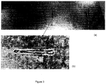
- Figures 6 and 7 show a lap weld produced using the process of the instant invention, wherein Figure 6 shows a photographic representation of a section of the weld shown in Figure 1 , and Figure 7 shows a photographic representation of a plan view of the weld shown in Figure 1 .
- the laser power is fixed at 4 kW and the beam is focused on the top surface of the component.
- the humping effect takes place at a speed of about 20 m/min.
- the height of the humps is relatively high, i.e. it can be over 0.5 mm.
- the hump height is decreasing.
- the droplets disappear along the weld bead. This speed limit is laser specific. With the laser used in generating Figure 5 , the humping effect is barely seen when the speed is above 80 m/min.
- the humping effect occurs at a speed of 30 m/min for this laser.
- This experimental data verifies that the welding speed for initialization of the humping effect decreases with increasing laser power.
- the laser power is decreased further to 3 kW, the humping effect barely happens.
- the full laser power of 4 kW only a slight humping takes place at the welding speed of 30 m/min if the laser beam is defocused at 5 mm. Therefore, a higher power laser beam gives a better controllability of the humping effect.
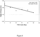
- Figure 8 shows a graphic representation of the height of the humps for a plurality of incident laser beam angles.
- the humps near perpendicular condition are slightly higher than those generated at relatively larger angles.
- the laser beam still produces proper humps for laser lap welding.
- Figure 9 shows a graphic representation of the dependence of the hump height on the scanning speed when the tilted angle of the laser beam is at 40 degrees.
- the laser power to generate these humps is at 4 kW. It can be seen from Figure 9 that the scan speed of the laser beam is the main controlling factor to generate humps with the desired height.
- a gap of 0.1 - 0.2 mm in size is required between the components to be welded.
- a laser beam at a power of 4 kW is capable of producing an adequate gap for a good quality lap weld with a scan speed in the range from 60 - 80 m/min.
- the humping effect occurs when a scan speed of a laser beam exceeds a certain limit. This limit is depending on the laser power and beam spot size.
- the height of the humps varies with the scan speed. For the example described above, humps with a height of 0.1 - 0.2 mm can be generated in a scan speed range from 60 to 80 m/min.
- the humping effect can be used advantageously in a pre-process to generate a desired gap for laser beam lap welding of sheet metals coated with a material having a low vaporization temperature.
- the gap size is controllable by varying the scan speed.
- the preferred humping effect can also be produced when the laser beam incident angle varies from 0 to 50 degrees.
- the combination of pre-process and lap welding process is well suitable for remote laser beam welding in which high speed scanning is easily achieved.
- the pre-process Since the pre-process is performed at a high speed, it only requires a fraction of the welding time to complete the whole pre-process. Hence, remote laser beam lap welding utilizing the humping effect is a practical technology for industrial applications.
- the process in accordance with the instant invention can be applied to components of any material thickness.
- the height of the protuberances is not controllable. As disclosed heretofore, in accordance with the instant invention, the height of the protuberances is controllable by controlling the scanning speed of the laser beam.
Landscapes
- Engineering & Computer Science (AREA)
- Physics & Mathematics (AREA)
- Optics & Photonics (AREA)
- Plasma & Fusion (AREA)
- Mechanical Engineering (AREA)
- Laser Beam Processing (AREA)
Claims (14)
- Verfahren zum Laserschweißen von ersten und zweiten Komponenten (10, 12), umfassend die Schritte von:Erzeugen von Vorsprüngen (17) auf der Oberfläche der ersten Komponente (10);Nebeneinanderstellen der ersten und zweiten Komponente (10, 12), so dass gegenüberliegende Oberflächen (15, 16) der ersten und zweiten Komponente (10, 12) durch die Vorsprünge (17) auf der Oberfläche (13) der ersten Komponente (10) getrennt sind; undLaserschweißen der ersten und zweiten Komponenten (10, 12) durch Scannen eines Laserstrahls (19) in einem Bereich, in dem die Oberflächen (10, 12) durch die Vorsprünge (17) getrennt sind,dadurch gekennzeichnet, dasswobei das Erzeugen von Vorsprüngen (17) auf der Oberfläche der ersten Komponente (10) durch Bewegen des Laserstrahls (19) über einen Abschnitt einer Oberfläche (13) der ersten Komponente (10) mit einer Geschwindigkeit erfolgt, die ausreicht, um die Vorsprünge (17) mittels eines Humpingeffekts zu erzeugen.
- Verfahren nach Anspruch 1, wobei die ersten und zweiten Komponenten (10, 12) aus Metall oder einer Metalllegierung hergestellt sind und worin mindestens eine der ersten und zweiten Komponenten (10, 12) mit einem Material (18) beschichtet ist, mit einer Verdampfungstemperatur die niedriger ist als ein Schmelzpunkt des Metalls oder der Metalllegierung.
- Verfahren nach Anspruch 2, wobei die erste und zweite Komponente (10, 12) aus Stahl hergestellt sind.
- Verfahren nach Anspruch 2, wobei die erste und zweite Komponente (10, 12) mit mindestens einem von Zink, Zinkoxid, Magnesium und Magnesiumoxid beschichtet sind.
- Verfahren nach Anspruch 1, wobei die Vorsprünge (17) ein Muster erzeugen, das im Wesentlichen einem durch den Laserschweißschritt erzeugten Schweißmuster entspricht.
- Verfahren nach Anspruch 1, wobei die Vorsprünge (17) ein Muster erzeugen, das sich von einem durch den Laserschweißschritt erzeugten Schweißmuster unterscheidet.
- Verfahren nach Anspruch 1, wobei der Laserstrahl (19) durch einen entfernten Laserschweißkopf bewegt wird.
- Verfahren nach Anspruch 1, ferner umfassend den Schritt des Einklemmens der ersten und zweiten Komponente (10, 12) miteinander vor dem Schritt des Laserschweißens.
- Verfahren nach Anspruch 1, ferner umfassend den Schritt des Steuerns einer Höhe der Vorsprünge (17) durch Steuern einer Scangeschwindigkeit des Laserstrahls (19).
- Verfahren nach Anspruch 1, ferner umfassend den Schritt des Steuerns einer Höhe der Vorsprünge (17) durch Steuern einer Intensität des Laserstrahls (19).
- Verfahren nach Anspruch 10, wobei der Schritt zum Steuern der Intensität des Laserstrahls (19) das Steuern einer Laserleistung und einer Strahlfleckgröße des Laserstrahls (19) beinhaltet.
- Verfahren nach Anspruch 1, wobei die Vorsprünge (17) erzeugt werden, wenn ein Einfallswinkel des Laserstrahls (19) zu einem großen Grad verändert werden kann.
- Verfahren nach Anspruch 9 oder 10, wobei die Höhe der Vorsprünge (17) von etwa 0,1 bis etwa 0,2 mm beträgt.
- Verfahren nach Anspruch 9, worin die Scangeschwindigkeit etwa 60 bis 80 m/min beträgt.
Applications Claiming Priority (2)
| Application Number | Priority Date | Filing Date | Title |
|---|---|---|---|
| US36070810P | 2010-07-01 | 2010-07-01 | |
| PCT/CA2011/000781 WO2012000106A1 (en) | 2010-07-01 | 2011-07-04 | Laser-based lap welding of sheet metal components using laser induced protuberances to control gap |
Publications (3)
| Publication Number | Publication Date |
|---|---|
| EP2588268A1 EP2588268A1 (de) | 2013-05-08 |
| EP2588268A4 EP2588268A4 (de) | 2017-10-04 |
| EP2588268B1 true EP2588268B1 (de) | 2019-02-20 |
Family
ID=45401267
Family Applications (1)
| Application Number | Title | Priority Date | Filing Date |
|---|---|---|---|
| EP11800030.6A Active EP2588268B1 (de) | 2010-07-01 | 2011-07-04 | Laserbasiertes überlappungsschweissverfahren für metallblechkomponenten mit laserinduzierten ausstülpungen zur abstandskontrolle |
Country Status (8)
| Country | Link |
|---|---|
| US (1) | US9737960B2 (de) |
| EP (1) | EP2588268B1 (de) |
| JP (1) | JP2013530048A (de) |
| CN (1) | CN102958641A (de) |
| BR (1) | BR112012033769A2 (de) |
| CA (1) | CA2802611C (de) |
| MX (1) | MX369557B (de) |
| WO (1) | WO2012000106A1 (de) |
Cited By (1)
| Publication number | Priority date | Publication date | Assignee | Title |
|---|---|---|---|---|
| WO2023066468A1 (en) * | 2021-10-19 | 2023-04-27 | Ipg Photonics Corporation | Low hazard laser welding system with dimpling functions and method |
Families Citing this family (35)
| Publication number | Priority date | Publication date | Assignee | Title |
|---|---|---|---|---|
| KR101272050B1 (ko) * | 2011-11-11 | 2013-06-07 | 주식회사 성우하이텍 | 레이저 용접방법 |
| WO2013163433A1 (en) * | 2012-04-26 | 2013-10-31 | Alere San Diego, Inc. | Laser joining device |
| CN102922817A (zh) * | 2012-11-20 | 2013-02-13 | 无锡汉神电气有限公司 | 用于激光叠焊的镀锌板及其焊接工艺 |
| BR112015019101B1 (pt) | 2013-02-15 | 2020-04-22 | Nissan Motor | método de soldagem a laser e dispositivo de soldagem a laser |
| FR3003492B1 (fr) * | 2013-03-19 | 2015-03-27 | Peugeot Citroen Automobiles Sa | Procede de traitement pour produire par faisceau laser des protuberances d'espacement dans une tole d'un assemblage |
| MX387869B (es) * | 2014-02-06 | 2025-03-19 | Nippon Steel Corp | Metodo de soldadura por solapado, union de solapa, metodo de produccion para union de solapa, y parte automotriz. |
| JP6343971B2 (ja) * | 2014-03-10 | 2018-06-20 | 日産自動車株式会社 | レーザー溶接方法、およびレーザー溶接装置 |
| JP6252262B2 (ja) * | 2014-03-10 | 2017-12-27 | 日産自動車株式会社 | レーザー溶接方法、およびレーザー溶接装置 |
| WO2015172797A1 (de) * | 2014-05-16 | 2015-11-19 | Trumpf Laser- Und Systemtechnik Gmbh | Fügeverfahren und -vorrichtung zum verbinden von zwei metallbauteilen, insbesondere einem stahlbauteil mit einem aluminiumbauteil; entsprechendes verbundbauteil |
| MX2017005315A (es) * | 2014-10-30 | 2017-06-28 | Nippon Steel & Sumitomo Metal Corp | Union de soldadura por laser y metodo de produccion de la misma. |
| GB201502149D0 (en) * | 2015-02-09 | 2015-03-25 | Spi Lasers Uk Ltd | Apparatus and method for laser welding |
| MX366999B (es) * | 2015-11-17 | 2019-08-02 | Nissan Motor | Metodo de soldadura con laser y dispositivo de soldadura con laser. |
| US10512986B2 (en) * | 2016-02-15 | 2019-12-24 | Ford Global Technologies, Llc | Laser welding process |
| EP3216552B1 (de) * | 2016-03-09 | 2018-12-12 | NGK Spark Plug Co., Ltd. | Laserschweissverfahren, verfahren zur herstellung von geschweissten körpern, verfahren zur herstellung einer elektrode für eine zündkerze und verfahren zur herstellung einer zündkerze unter verwendung solcher laserschweissverfahren |
| GB2551241B (en) * | 2016-03-31 | 2019-04-17 | Porsche Ag | Method for machining a surface of a metal component |
| DE102017201648A1 (de) | 2016-03-31 | 2017-10-05 | Dr. Ing. H.C. F. Porsche Ag | Verfahren zum Bearbeiten einer Oberfläche eines metallischen Bauteils und metallisches Bauteil |
| CN109153097A (zh) * | 2016-04-14 | 2019-01-04 | 通用汽车环球科技运作有限责任公司 | 经涂覆的钢的集成预钻和激光点焊 |
| WO2018010132A1 (en) * | 2016-07-14 | 2018-01-18 | GM Global Technology Operations LLC | Multi-beam laser spot welding of coated steels |
| CN106041308A (zh) * | 2016-08-18 | 2016-10-26 | 安徽巨自动化装备有限公司 | 铝合金车身激光熔焊板件间隙控制方法 |
| IT201600103882A1 (it) * | 2016-10-17 | 2018-04-17 | Stv Serrature S R L | Metodo per la realizzazione di corpi scatolari per serrature |
| DE102017105900A1 (de) * | 2017-03-20 | 2018-09-20 | Kirchhoff Automotive Deutschland Gmbh | Verfahren zum stirnseitigen Laserschweißen |
| CN107252971B (zh) * | 2017-04-20 | 2019-11-19 | 武汉华工激光工程有限责任公司 | 镀锌板激光叠焊方法 |
| CN110914014B (zh) * | 2017-06-13 | 2021-07-20 | 通用汽车环球科技运作有限责任公司 | 用于使用焊接路径的组合激光焊接金属工件的方法 |
| EP3441178A1 (de) * | 2017-08-09 | 2019-02-13 | Autotech Engineering A.I.E. | Verfahren zur verbindung von zwei blechen |
| CN108311787A (zh) * | 2018-01-18 | 2018-07-24 | 上海业识科技有限公司 | 基于连续激光、准连续激光的不锈钢面板表面焊接工艺 |
| WO2019189927A1 (ja) * | 2018-03-30 | 2019-10-03 | 古河電気工業株式会社 | 溶接方法および溶接装置 |
| EP3584031A1 (de) * | 2018-06-20 | 2019-12-25 | Sund Birsta AB | Umreifungsmaschine und verfahren zum befestigen eines beschichteten metallbandstücks in einer schlaufe um ein oder mehrere objekte |
| US11427144B2 (en) | 2018-11-27 | 2022-08-30 | Shape Corp. | Galvanized multi-tubular beam and method of continuously forming the same |
| US11583954B2 (en) * | 2019-03-04 | 2023-02-21 | Kabushiki Kaisha Toshiba | Welding method |
| DE102019121527A1 (de) * | 2019-08-09 | 2021-02-11 | Ii-Vi Delaware, Inc. | Verfahren zur optimierten strukturierung eines 2d-codes auf einem bauteil |
| CN110576261B (zh) * | 2019-08-21 | 2021-06-25 | 中车青岛四方机车车辆股份有限公司 | 激光叠焊装置及其焊接方法 |
| IL269566B (en) | 2019-09-23 | 2021-04-29 | Elbit Systems Electro Optics Elop Ltd | Systems and methods for controlling output of light towards objects |
| CN111230302A (zh) * | 2020-02-24 | 2020-06-05 | 中国第一汽车股份有限公司 | 一种用于车门内板总成的焊接方法 |
| WO2023110583A1 (de) * | 2021-12-17 | 2023-06-22 | Trumpf Laser- Und Systemtechnik Gmbh | VERFAHREN ZUM SCHWEIßEN VON ZINKBESCHICHTETEN STAHLBLECHEN MIT EINEM LASERSTRAHL |
| CN116441727A (zh) * | 2023-05-12 | 2023-07-18 | 武汉锐科光纤激光技术股份有限公司 | 激光焊接方法 |
Family Cites Families (2)
| Publication number | Priority date | Publication date | Assignee | Title |
|---|---|---|---|---|
| CA2209804A1 (en) * | 1997-08-15 | 1999-02-15 | Hongping Gu | Method of laser beam welding of zinc-coated steel sheet |
| FR2915912B1 (fr) | 2007-05-11 | 2010-02-26 | Peugeot Citroen Automobiles Sa | Procede de soudage au laser d'elements metalliques. |
-
2011
- 2011-07-04 EP EP11800030.6A patent/EP2588268B1/de active Active
- 2011-07-04 CN CN2011800323996A patent/CN102958641A/zh active Pending
- 2011-07-04 MX MX2012015278A patent/MX369557B/es active IP Right Grant
- 2011-07-04 JP JP2013516928A patent/JP2013530048A/ja not_active Withdrawn
- 2011-07-04 CA CA2802611A patent/CA2802611C/en active Active
- 2011-07-04 WO PCT/CA2011/000781 patent/WO2012000106A1/en not_active Ceased
- 2011-07-04 BR BR112012033769A patent/BR112012033769A2/pt not_active Application Discontinuation
- 2011-07-04 US US13/805,103 patent/US9737960B2/en active Active
Non-Patent Citations (1)
| Title |
|---|
| None * |
Cited By (1)
| Publication number | Priority date | Publication date | Assignee | Title |
|---|---|---|---|---|
| WO2023066468A1 (en) * | 2021-10-19 | 2023-04-27 | Ipg Photonics Corporation | Low hazard laser welding system with dimpling functions and method |
Also Published As
| Publication number | Publication date |
|---|---|
| US9737960B2 (en) | 2017-08-22 |
| BR112012033769A2 (pt) | 2017-06-06 |
| JP2013530048A (ja) | 2013-07-25 |
| CA2802611A1 (en) | 2012-01-05 |
| MX369557B (es) | 2019-11-12 |
| EP2588268A4 (de) | 2017-10-04 |
| WO2012000106A1 (en) | 2012-01-05 |
| CN102958641A (zh) | 2013-03-06 |
| MX2012015278A (es) | 2013-02-27 |
| CA2802611C (en) | 2018-08-07 |
| EP2588268A1 (de) | 2013-05-08 |
| US20130087540A1 (en) | 2013-04-11 |
Similar Documents
| Publication | Publication Date | Title |
|---|---|---|
| US9737960B2 (en) | Laser-based lap welding of sheet metal components using laser induced protuberances to control gap | |
| EP2666579B1 (de) | Hybrides Laserlichtbogenschweißverfahren und Vorrichtung | |
| EP2402107B1 (de) | Verfahren zum Hybrid-Laser-lichtbogenschweißen mit zwei Laserstrahlen | |
| JP4209326B2 (ja) | 2枚の被膜された金属シートを高エネルギー密度のビームで重複溶接するための方法および装置 | |
| CN102652046B (zh) | 焊接方法和焊接装置 | |
| EP2246144B1 (de) | Verfahren zum Hochleistungs-Laserstrahlschweißen von Werkstücken mit einer über die Oberfläche der Werkstücke protrudierenden metallischen Folie ; Anordnung dafür | |
| US20180214983A1 (en) | Method for laser welding aluminum workpieces | |
| US10888955B2 (en) | Avoiding hot cracks during laser welding of a workpiece stack-up assembly of aluminum alloy workpieces | |
| JP5601003B2 (ja) | レーザ・アーク複合溶接方法、及び突き合わせ溶接用金属板の開先 | |
| CN109070271A (zh) | 叠置的铝工件的激光点焊 | |
| JPH0732180A (ja) | 亜鉛めっき鋼板のレーザ溶接方法 | |
| JP4867599B2 (ja) | レーザ溶接方法およびその装置 | |
| JP2014024078A (ja) | レーザ溶接装置 | |
| JP2012206145A (ja) | ホットワイヤレーザ溶接方法と装置 | |
| Victor | Hybrid laser arc welding | |
| EP1118420A2 (de) | Überlappschweissen mittels eines geneigten Strahls | |
| JP2018069258A (ja) | レーザ溶接方法及びレーザ溶接装置 | |
| Gu et al. | A practical use of humping effect in laser beam welding | |
| Salminen et al. | Effect of welding parameters on high-power diode laser welding of thin sheet | |
| Gu et al. | Remote laser welding of zinc-coated sheet metal component in a lap configuration utilizing humping effect | |
| JP6947669B2 (ja) | レーザ溶接方法 | |
| JP4998634B1 (ja) | レーザ溶接方法 | |
| JP2024539110A (ja) | ディンプリング機能を有する低危険性レーザ溶接システムおよび方法 | |
| JP2018001191A (ja) | スポット溶接方法及び溶接製品 | |
| JP2003334687A (ja) | レーザ溶接方法 |
Legal Events
| Date | Code | Title | Description |
|---|---|---|---|
| PUAI | Public reference made under article 153(3) epc to a published international application that has entered the european phase |
Free format text: ORIGINAL CODE: 0009012 |
|
| 17P | Request for examination filed |
Effective date: 20130102 |
|
| AK | Designated contracting states |
Kind code of ref document: A1 Designated state(s): AL AT BE BG CH CY CZ DE DK EE ES FI FR GB GR HR HU IE IS IT LI LT LU LV MC MK MT NL NO PL PT RO RS SE SI SK SM TR |
|
| DAX | Request for extension of the european patent (deleted) | ||
| RA4 | Supplementary search report drawn up and despatched (corrected) |
Effective date: 20170906 |
|
| RIC1 | Information provided on ipc code assigned before grant |
Ipc: B23K 26/00 20140101ALI20170831BHEP Ipc: B23K 26/08 20140101ALI20170831BHEP Ipc: B23K 26/244 20140101ALI20170831BHEP Ipc: B23K 26/20 20140101AFI20170831BHEP |
|
| RIC1 | Information provided on ipc code assigned before grant |
Ipc: B23K 26/20 20060101AFI20180716BHEP Ipc: B23K 26/244 20140101ALI20180716BHEP Ipc: B23K 26/00 20140101ALI20180716BHEP Ipc: B23K 26/08 20060101ALI20180716BHEP |
|
| GRAP | Despatch of communication of intention to grant a patent |
Free format text: ORIGINAL CODE: EPIDOSNIGR1 |
|
| STAA | Information on the status of an ep patent application or granted ep patent |
Free format text: STATUS: GRANT OF PATENT IS INTENDED |
|
| INTG | Intention to grant announced |
Effective date: 20180906 |
|
| GRAS | Grant fee paid |
Free format text: ORIGINAL CODE: EPIDOSNIGR3 |
|
| GRAA | (expected) grant |
Free format text: ORIGINAL CODE: 0009210 |
|
| STAA | Information on the status of an ep patent application or granted ep patent |
Free format text: STATUS: THE PATENT HAS BEEN GRANTED |
|
| AK | Designated contracting states |
Kind code of ref document: B1 Designated state(s): AL AT BE BG CH CY CZ DE DK EE ES FI FR GB GR HR HU IE IS IT LI LT LU LV MC MK MT NL NO PL PT RO RS SE SI SK SM TR |
|
| REG | Reference to a national code |
Ref country code: GB Ref legal event code: FG4D |
|
| REG | Reference to a national code |
Ref country code: CH Ref legal event code: EP |
|
| REG | Reference to a national code |
Ref country code: DE Ref legal event code: R096 Ref document number: 602011056391 Country of ref document: DE |
|
| REG | Reference to a national code |
Ref country code: AT Ref legal event code: REF Ref document number: 1097548 Country of ref document: AT Kind code of ref document: T Effective date: 20190315 |
|
| REG | Reference to a national code |
Ref country code: IE Ref legal event code: FG4D |
|
| REG | Reference to a national code |
Ref country code: NL Ref legal event code: MP Effective date: 20190220 |
|
| REG | Reference to a national code |
Ref country code: LT Ref legal event code: MG4D |
|
| PG25 | Lapsed in a contracting state [announced via postgrant information from national office to epo] |
Ref country code: LT Free format text: LAPSE BECAUSE OF FAILURE TO SUBMIT A TRANSLATION OF THE DESCRIPTION OR TO PAY THE FEE WITHIN THE PRESCRIBED TIME-LIMIT Effective date: 20190220 Ref country code: SE Free format text: LAPSE BECAUSE OF FAILURE TO SUBMIT A TRANSLATION OF THE DESCRIPTION OR TO PAY THE FEE WITHIN THE PRESCRIBED TIME-LIMIT Effective date: 20190220 Ref country code: NO Free format text: LAPSE BECAUSE OF FAILURE TO SUBMIT A TRANSLATION OF THE DESCRIPTION OR TO PAY THE FEE WITHIN THE PRESCRIBED TIME-LIMIT Effective date: 20190520 Ref country code: PT Free format text: LAPSE BECAUSE OF FAILURE TO SUBMIT A TRANSLATION OF THE DESCRIPTION OR TO PAY THE FEE WITHIN THE PRESCRIBED TIME-LIMIT Effective date: 20190620 Ref country code: FI Free format text: LAPSE BECAUSE OF FAILURE TO SUBMIT A TRANSLATION OF THE DESCRIPTION OR TO PAY THE FEE WITHIN THE PRESCRIBED TIME-LIMIT Effective date: 20190220 |
|
| PG25 | Lapsed in a contracting state [announced via postgrant information from national office to epo] |
Ref country code: RS Free format text: LAPSE BECAUSE OF FAILURE TO SUBMIT A TRANSLATION OF THE DESCRIPTION OR TO PAY THE FEE WITHIN THE PRESCRIBED TIME-LIMIT Effective date: 20190220 Ref country code: HR Free format text: LAPSE BECAUSE OF FAILURE TO SUBMIT A TRANSLATION OF THE DESCRIPTION OR TO PAY THE FEE WITHIN THE PRESCRIBED TIME-LIMIT Effective date: 20190220 Ref country code: NL Free format text: LAPSE BECAUSE OF FAILURE TO SUBMIT A TRANSLATION OF THE DESCRIPTION OR TO PAY THE FEE WITHIN THE PRESCRIBED TIME-LIMIT Effective date: 20190220 Ref country code: LV Free format text: LAPSE BECAUSE OF FAILURE TO SUBMIT A TRANSLATION OF THE DESCRIPTION OR TO PAY THE FEE WITHIN THE PRESCRIBED TIME-LIMIT Effective date: 20190220 Ref country code: BG Free format text: LAPSE BECAUSE OF FAILURE TO SUBMIT A TRANSLATION OF THE DESCRIPTION OR TO PAY THE FEE WITHIN THE PRESCRIBED TIME-LIMIT Effective date: 20190520 Ref country code: IS Free format text: LAPSE BECAUSE OF FAILURE TO SUBMIT A TRANSLATION OF THE DESCRIPTION OR TO PAY THE FEE WITHIN THE PRESCRIBED TIME-LIMIT Effective date: 20190620 Ref country code: GR Free format text: LAPSE BECAUSE OF FAILURE TO SUBMIT A TRANSLATION OF THE DESCRIPTION OR TO PAY THE FEE WITHIN THE PRESCRIBED TIME-LIMIT Effective date: 20190521 |
|
| REG | Reference to a national code |
Ref country code: AT Ref legal event code: MK05 Ref document number: 1097548 Country of ref document: AT Kind code of ref document: T Effective date: 20190220 |
|
| PG25 | Lapsed in a contracting state [announced via postgrant information from national office to epo] |
Ref country code: EE Free format text: LAPSE BECAUSE OF FAILURE TO SUBMIT A TRANSLATION OF THE DESCRIPTION OR TO PAY THE FEE WITHIN THE PRESCRIBED TIME-LIMIT Effective date: 20190220 Ref country code: DK Free format text: LAPSE BECAUSE OF FAILURE TO SUBMIT A TRANSLATION OF THE DESCRIPTION OR TO PAY THE FEE WITHIN THE PRESCRIBED TIME-LIMIT Effective date: 20190220 Ref country code: SK Free format text: LAPSE BECAUSE OF FAILURE TO SUBMIT A TRANSLATION OF THE DESCRIPTION OR TO PAY THE FEE WITHIN THE PRESCRIBED TIME-LIMIT Effective date: 20190220 Ref country code: AL Free format text: LAPSE BECAUSE OF FAILURE TO SUBMIT A TRANSLATION OF THE DESCRIPTION OR TO PAY THE FEE WITHIN THE PRESCRIBED TIME-LIMIT Effective date: 20190220 Ref country code: CZ Free format text: LAPSE BECAUSE OF FAILURE TO SUBMIT A TRANSLATION OF THE DESCRIPTION OR TO PAY THE FEE WITHIN THE PRESCRIBED TIME-LIMIT Effective date: 20190220 Ref country code: ES Free format text: LAPSE BECAUSE OF FAILURE TO SUBMIT A TRANSLATION OF THE DESCRIPTION OR TO PAY THE FEE WITHIN THE PRESCRIBED TIME-LIMIT Effective date: 20190220 Ref country code: IT Free format text: LAPSE BECAUSE OF FAILURE TO SUBMIT A TRANSLATION OF THE DESCRIPTION OR TO PAY THE FEE WITHIN THE PRESCRIBED TIME-LIMIT Effective date: 20190220 Ref country code: RO Free format text: LAPSE BECAUSE OF FAILURE TO SUBMIT A TRANSLATION OF THE DESCRIPTION OR TO PAY THE FEE WITHIN THE PRESCRIBED TIME-LIMIT Effective date: 20190220 |
|
| REG | Reference to a national code |
Ref country code: DE Ref legal event code: R097 Ref document number: 602011056391 Country of ref document: DE |
|
| PG25 | Lapsed in a contracting state [announced via postgrant information from national office to epo] |
Ref country code: SM Free format text: LAPSE BECAUSE OF FAILURE TO SUBMIT A TRANSLATION OF THE DESCRIPTION OR TO PAY THE FEE WITHIN THE PRESCRIBED TIME-LIMIT Effective date: 20190220 Ref country code: PL Free format text: LAPSE BECAUSE OF FAILURE TO SUBMIT A TRANSLATION OF THE DESCRIPTION OR TO PAY THE FEE WITHIN THE PRESCRIBED TIME-LIMIT Effective date: 20190220 |
|
| PLBE | No opposition filed within time limit |
Free format text: ORIGINAL CODE: 0009261 |
|
| STAA | Information on the status of an ep patent application or granted ep patent |
Free format text: STATUS: NO OPPOSITION FILED WITHIN TIME LIMIT |
|
| PG25 | Lapsed in a contracting state [announced via postgrant information from national office to epo] |
Ref country code: AT Free format text: LAPSE BECAUSE OF FAILURE TO SUBMIT A TRANSLATION OF THE DESCRIPTION OR TO PAY THE FEE WITHIN THE PRESCRIBED TIME-LIMIT Effective date: 20190220 |
|
| 26N | No opposition filed |
Effective date: 20191121 |
|
| PG25 | Lapsed in a contracting state [announced via postgrant information from national office to epo] |
Ref country code: MC Free format text: LAPSE BECAUSE OF FAILURE TO SUBMIT A TRANSLATION OF THE DESCRIPTION OR TO PAY THE FEE WITHIN THE PRESCRIBED TIME-LIMIT Effective date: 20190220 Ref country code: SI Free format text: LAPSE BECAUSE OF FAILURE TO SUBMIT A TRANSLATION OF THE DESCRIPTION OR TO PAY THE FEE WITHIN THE PRESCRIBED TIME-LIMIT Effective date: 20190220 |
|
| REG | Reference to a national code |
Ref country code: CH Ref legal event code: PL |
|
| GBPC | Gb: european patent ceased through non-payment of renewal fee |
Effective date: 20190704 |
|
| PG25 | Lapsed in a contracting state [announced via postgrant information from national office to epo] |
Ref country code: TR Free format text: LAPSE BECAUSE OF FAILURE TO SUBMIT A TRANSLATION OF THE DESCRIPTION OR TO PAY THE FEE WITHIN THE PRESCRIBED TIME-LIMIT Effective date: 20190220 |
|
| REG | Reference to a national code |
Ref country code: BE Ref legal event code: MM Effective date: 20190731 |
|
| PG25 | Lapsed in a contracting state [announced via postgrant information from national office to epo] |
Ref country code: GB Free format text: LAPSE BECAUSE OF NON-PAYMENT OF DUE FEES Effective date: 20190704 |
|
| PG25 | Lapsed in a contracting state [announced via postgrant information from national office to epo] |
Ref country code: BE Free format text: LAPSE BECAUSE OF NON-PAYMENT OF DUE FEES Effective date: 20190731 Ref country code: LI Free format text: LAPSE BECAUSE OF NON-PAYMENT OF DUE FEES Effective date: 20190731 Ref country code: LU Free format text: LAPSE BECAUSE OF NON-PAYMENT OF DUE FEES Effective date: 20190704 Ref country code: CH Free format text: LAPSE BECAUSE OF NON-PAYMENT OF DUE FEES Effective date: 20190731 |
|
| PG25 | Lapsed in a contracting state [announced via postgrant information from national office to epo] |
Ref country code: FR Free format text: LAPSE BECAUSE OF NON-PAYMENT OF DUE FEES Effective date: 20190731 |
|
| PG25 | Lapsed in a contracting state [announced via postgrant information from national office to epo] |
Ref country code: IE Free format text: LAPSE BECAUSE OF NON-PAYMENT OF DUE FEES Effective date: 20190704 |
|
| PG25 | Lapsed in a contracting state [announced via postgrant information from national office to epo] |
Ref country code: CY Free format text: LAPSE BECAUSE OF FAILURE TO SUBMIT A TRANSLATION OF THE DESCRIPTION OR TO PAY THE FEE WITHIN THE PRESCRIBED TIME-LIMIT Effective date: 20190220 |
|
| PG25 | Lapsed in a contracting state [announced via postgrant information from national office to epo] |
Ref country code: HU Free format text: LAPSE BECAUSE OF FAILURE TO SUBMIT A TRANSLATION OF THE DESCRIPTION OR TO PAY THE FEE WITHIN THE PRESCRIBED TIME-LIMIT; INVALID AB INITIO Effective date: 20110704 Ref country code: MT Free format text: LAPSE BECAUSE OF FAILURE TO SUBMIT A TRANSLATION OF THE DESCRIPTION OR TO PAY THE FEE WITHIN THE PRESCRIBED TIME-LIMIT Effective date: 20190220 |
|
| PG25 | Lapsed in a contracting state [announced via postgrant information from national office to epo] |
Ref country code: MK Free format text: LAPSE BECAUSE OF FAILURE TO SUBMIT A TRANSLATION OF THE DESCRIPTION OR TO PAY THE FEE WITHIN THE PRESCRIBED TIME-LIMIT Effective date: 20190220 |
|
| PGFP | Annual fee paid to national office [announced via postgrant information from national office to epo] |
Ref country code: DE Payment date: 20250604 Year of fee payment: 15 |