EP2588385B1 - Karton mit einsatz - Google Patents
Karton mit einsatz Download PDFInfo
- Publication number
- EP2588385B1 EP2588385B1 EP11801373.9A EP11801373A EP2588385B1 EP 2588385 B1 EP2588385 B1 EP 2588385B1 EP 11801373 A EP11801373 A EP 11801373A EP 2588385 B1 EP2588385 B1 EP 2588385B1
- Authority
- EP
- European Patent Office
- Prior art keywords
- carton
- end flap
- reinforcing
- panel
- flap
- Prior art date
- Legal status (The legal status is an assumption and is not a legal conclusion. Google has not performed a legal analysis and makes no representation as to the accuracy of the status listed.)
- Not-in-force
Links
- 230000003014 reinforcing effect Effects 0.000 claims description 110
- 238000000034 method Methods 0.000 claims description 13
- 230000000452 restraining effect Effects 0.000 claims description 3
- 239000000463 material Substances 0.000 description 10
- 239000011087 paperboard Substances 0.000 description 7
- 235000013361 beverage Nutrition 0.000 description 5
- 230000002787 reinforcement Effects 0.000 description 5
- 239000010410 layer Substances 0.000 description 3
- 238000012986 modification Methods 0.000 description 3
- 230000004048 modification Effects 0.000 description 3
- 239000004927 clay Substances 0.000 description 2
- 239000011248 coating agent Substances 0.000 description 2
- 238000000576 coating method Methods 0.000 description 2
- 239000011521 glass Substances 0.000 description 2
- 239000003292 glue Substances 0.000 description 2
- 238000004806 packaging method and process Methods 0.000 description 2
- 239000000123 paper Substances 0.000 description 2
- VGGSQFUCUMXWEO-UHFFFAOYSA-N Ethene Chemical compound C=C VGGSQFUCUMXWEO-UHFFFAOYSA-N 0.000 description 1
- 229920000219 Ethylene vinyl alcohol Polymers 0.000 description 1
- 239000004677 Nylon Substances 0.000 description 1
- 239000004743 Polypropylene Substances 0.000 description 1
- 239000004793 Polystyrene Substances 0.000 description 1
- 239000000853 adhesive Substances 0.000 description 1
- 230000001070 adhesive effect Effects 0.000 description 1
- 230000004075 alteration Effects 0.000 description 1
- 229910052782 aluminium Inorganic materials 0.000 description 1
- XAGFODPZIPBFFR-UHFFFAOYSA-N aluminium Chemical compound [Al] XAGFODPZIPBFFR-UHFFFAOYSA-N 0.000 description 1
- 230000004888 barrier function Effects 0.000 description 1
- 239000011111 cardboard Substances 0.000 description 1
- 238000010276 construction Methods 0.000 description 1
- UFRKOOWSQGXVKV-UHFFFAOYSA-N ethene;ethenol Chemical compound C=C.OC=C UFRKOOWSQGXVKV-UHFFFAOYSA-N 0.000 description 1
- 239000004715 ethylene vinyl alcohol Substances 0.000 description 1
- 229920001903 high density polyethylene Polymers 0.000 description 1
- 239000004700 high-density polyethylene Substances 0.000 description 1
- 238000003780 insertion Methods 0.000 description 1
- 230000037431 insertion Effects 0.000 description 1
- 229920000092 linear low density polyethylene Polymers 0.000 description 1
- 239000004707 linear low-density polyethylene Substances 0.000 description 1
- 229920001684 low density polyethylene Polymers 0.000 description 1
- 239000004702 low-density polyethylene Substances 0.000 description 1
- 229910052751 metal Inorganic materials 0.000 description 1
- 239000002184 metal Substances 0.000 description 1
- 150000002739 metals Chemical class 0.000 description 1
- 239000000203 mixture Substances 0.000 description 1
- 229920001778 nylon Polymers 0.000 description 1
- 239000004033 plastic Substances 0.000 description 1
- 229920003023 plastic Polymers 0.000 description 1
- 229920000139 polyethylene terephthalate Polymers 0.000 description 1
- 239000005020 polyethylene terephthalate Substances 0.000 description 1
- 229920000915 polyvinyl chloride Polymers 0.000 description 1
- 239000004800 polyvinyl chloride Substances 0.000 description 1
- 239000002356 single layer Substances 0.000 description 1
- 239000002966 varnish Substances 0.000 description 1
- 230000003313 weakening effect Effects 0.000 description 1
Images


Classifications
-
- B—PERFORMING OPERATIONS; TRANSPORTING
- B65—CONVEYING; PACKING; STORING; HANDLING THIN OR FILAMENTARY MATERIAL
- B65D—CONTAINERS FOR STORAGE OR TRANSPORT OF ARTICLES OR MATERIALS, e.g. BAGS, BARRELS, BOTTLES, BOXES, CANS, CARTONS, CRATES, DRUMS, JARS, TANKS, HOPPERS, FORWARDING CONTAINERS; ACCESSORIES, CLOSURES, OR FITTINGS THEREFOR; PACKAGING ELEMENTS; PACKAGES
- B65D5/00—Rigid or semi-rigid containers of polygonal cross-section, e.g. boxes, cartons or trays, formed by folding or erecting one or more blanks made of paper
- B65D5/42—Details of containers or of foldable or erectable container blanks
- B65D5/44—Integral, inserted or attached portions forming internal or external fittings
- B65D5/441—Reinforcements
- B65D5/445—Reinforcements formed separately from the container
-
- B—PERFORMING OPERATIONS; TRANSPORTING
- B31—MAKING ARTICLES OF PAPER, CARDBOARD OR MATERIAL WORKED IN A MANNER ANALOGOUS TO PAPER; WORKING PAPER, CARDBOARD OR MATERIAL WORKED IN A MANNER ANALOGOUS TO PAPER
- B31B—MAKING CONTAINERS OF PAPER, CARDBOARD OR MATERIAL WORKED IN A MANNER ANALOGOUS TO PAPER
- B31B50/00—Making rigid or semi-rigid containers, e.g. boxes or cartons
- B31B50/26—Folding sheets, blanks or webs
-
- B—PERFORMING OPERATIONS; TRANSPORTING
- B31—MAKING ARTICLES OF PAPER, CARDBOARD OR MATERIAL WORKED IN A MANNER ANALOGOUS TO PAPER; WORKING PAPER, CARDBOARD OR MATERIAL WORKED IN A MANNER ANALOGOUS TO PAPER
- B31B—MAKING CONTAINERS OF PAPER, CARDBOARD OR MATERIAL WORKED IN A MANNER ANALOGOUS TO PAPER
- B31B50/00—Making rigid or semi-rigid containers, e.g. boxes or cartons
- B31B50/74—Auxiliary operations
- B31B50/81—Forming or attaching accessories, e.g. opening devices, closures or tear strings
-
- B—PERFORMING OPERATIONS; TRANSPORTING
- B65—CONVEYING; PACKING; STORING; HANDLING THIN OR FILAMENTARY MATERIAL
- B65D—CONTAINERS FOR STORAGE OR TRANSPORT OF ARTICLES OR MATERIALS, e.g. BAGS, BARRELS, BOTTLES, BOXES, CANS, CARTONS, CRATES, DRUMS, JARS, TANKS, HOPPERS, FORWARDING CONTAINERS; ACCESSORIES, CLOSURES, OR FITTINGS THEREFOR; PACKAGING ELEMENTS; PACKAGES
- B65D5/00—Rigid or semi-rigid containers of polygonal cross-section, e.g. boxes, cartons or trays, formed by folding or erecting one or more blanks made of paper
- B65D5/02—Rigid or semi-rigid containers of polygonal cross-section, e.g. boxes, cartons or trays, formed by folding or erecting one or more blanks made of paper by folding or erecting a single blank to form a tubular body with or without subsequent folding operations, or the addition of separate elements, to close the ends of the body
-
- B—PERFORMING OPERATIONS; TRANSPORTING
- B65—CONVEYING; PACKING; STORING; HANDLING THIN OR FILAMENTARY MATERIAL
- B65D—CONTAINERS FOR STORAGE OR TRANSPORT OF ARTICLES OR MATERIALS, e.g. BAGS, BARRELS, BOTTLES, BOXES, CANS, CARTONS, CRATES, DRUMS, JARS, TANKS, HOPPERS, FORWARDING CONTAINERS; ACCESSORIES, CLOSURES, OR FITTINGS THEREFOR; PACKAGING ELEMENTS; PACKAGES
- B65D5/00—Rigid or semi-rigid containers of polygonal cross-section, e.g. boxes, cartons or trays, formed by folding or erecting one or more blanks made of paper
- B65D5/02—Rigid or semi-rigid containers of polygonal cross-section, e.g. boxes, cartons or trays, formed by folding or erecting one or more blanks made of paper by folding or erecting a single blank to form a tubular body with or without subsequent folding operations, or the addition of separate elements, to close the ends of the body
- B65D5/0227—Rigid or semi-rigid containers of polygonal cross-section, e.g. boxes, cartons or trays, formed by folding or erecting one or more blanks made of paper by folding or erecting a single blank to form a tubular body with or without subsequent folding operations, or the addition of separate elements, to close the ends of the body with end closures formed by inward folding of flaps and securing them by heat-sealing, by applying adhesive to the flaps or by staples
-
- B—PERFORMING OPERATIONS; TRANSPORTING
- B65—CONVEYING; PACKING; STORING; HANDLING THIN OR FILAMENTARY MATERIAL
- B65D—CONTAINERS FOR STORAGE OR TRANSPORT OF ARTICLES OR MATERIALS, e.g. BAGS, BARRELS, BOTTLES, BOXES, CANS, CARTONS, CRATES, DRUMS, JARS, TANKS, HOPPERS, FORWARDING CONTAINERS; ACCESSORIES, CLOSURES, OR FITTINGS THEREFOR; PACKAGING ELEMENTS; PACKAGES
- B65D5/00—Rigid or semi-rigid containers of polygonal cross-section, e.g. boxes, cartons or trays, formed by folding or erecting one or more blanks made of paper
- B65D5/42—Details of containers or of foldable or erectable container blanks
- B65D5/44—Integral, inserted or attached portions forming internal or external fittings
- B65D5/46—Handles
- B65D5/46072—Handles integral with the container
-
- B—PERFORMING OPERATIONS; TRANSPORTING
- B65—CONVEYING; PACKING; STORING; HANDLING THIN OR FILAMENTARY MATERIAL
- B65D—CONTAINERS FOR STORAGE OR TRANSPORT OF ARTICLES OR MATERIALS, e.g. BAGS, BARRELS, BOTTLES, BOXES, CANS, CARTONS, CRATES, DRUMS, JARS, TANKS, HOPPERS, FORWARDING CONTAINERS; ACCESSORIES, CLOSURES, OR FITTINGS THEREFOR; PACKAGING ELEMENTS; PACKAGES
- B65D5/00—Rigid or semi-rigid containers of polygonal cross-section, e.g. boxes, cartons or trays, formed by folding or erecting one or more blanks made of paper
- B65D5/42—Details of containers or of foldable or erectable container blanks
- B65D5/44—Integral, inserted or attached portions forming internal or external fittings
- B65D5/46—Handles
- B65D5/46072—Handles integral with the container
- B65D5/4608—Handgrip holes
-
- B—PERFORMING OPERATIONS; TRANSPORTING
- B65—CONVEYING; PACKING; STORING; HANDLING THIN OR FILAMENTARY MATERIAL
- B65D—CONTAINERS FOR STORAGE OR TRANSPORT OF ARTICLES OR MATERIALS, e.g. BAGS, BARRELS, BOTTLES, BOXES, CANS, CARTONS, CRATES, DRUMS, JARS, TANKS, HOPPERS, FORWARDING CONTAINERS; ACCESSORIES, CLOSURES, OR FITTINGS THEREFOR; PACKAGING ELEMENTS; PACKAGES
- B65D5/00—Rigid or semi-rigid containers of polygonal cross-section, e.g. boxes, cartons or trays, formed by folding or erecting one or more blanks made of paper
- B65D5/42—Details of containers or of foldable or erectable container blanks
- B65D5/64—Lids
- B65D5/66—Hinged lids
- B65D5/6626—Hinged lids formed by folding extensions of a side panel of a container body formed by erecting a "cross-like" blank
- B65D5/6629—Hinged lids formed by folding extensions of a side panel of a container body formed by erecting a "cross-like" blank the lid being formed by two mating halves joined to opposite edges of the container body
- B65D5/6632—Hinged lids formed by folding extensions of a side panel of a container body formed by erecting a "cross-like" blank the lid being formed by two mating halves joined to opposite edges of the container body the lid-halves being held in closed position by flaps or tabs provided at their side edges only
Definitions
- the present disclosure generally relates to cartons for holding beverage containers or other types of articles. More specifically, the present disclosure relates to cartons having a reinforcing insert. In still greater detail, the present invention relates to a carton according to the preamble of claim 1. Moreover, this invention relates to, in combination, a carton blank and an insert blank, according to the preamble of claim 15 and to a method of forming a carton from a carton blank and an insert blank.
- a carton of the generic type defined in the preamble of claim 1 is disclosed in US 2008/128479 A1 , the respective carton including a substantially tubular structure having an outer top panel.
- the carton also has an end wall structure including an outer top end flap foldably connected to the outer top panel along its end edge.
- the outer top end flap includes a handle opening having a weight-bearing region.
- the carton also has an insert including an inner top panel and an inner top end flap.
- the inner top panel is disposed in flat-face condition substantially in registry with the outer top panel.
- the inner top end flap is foldably connected to the inner top panel along an end edge of the inner top panel.
- the inner top end flap is substantially in registry with the outer top end flap and has a distal edge disposed adjacent the weight-bearing region of the handle opening.
- the insert further includes at least one auxiliary reinforcement flap disposed in flat-face condition with the inner top end flap so as to provide multiple-ply structure adjacent the handle opening weight-bearing region.
- US 2010/044420 A1 discloses a carton for containing a plurality of articles.
- the carton has panels that extend at least partially around an interior of the carton.
- the panels comprise a top panel, a bottom panel, a first side panel, and a second side panel.
- At least two end flaps are respectively foldably attached to respective panels of the plurality of panels, wherein the end flaps are overlapped with respect to one another and thereby at least partially form a closed end of the carton.
- the carton includes a handle in the closed end of the carton for grasping and carrying the carton.
- the carton comprises a reinforcing insert attached to at least one of the panels for reinforcing the handle.
- US 6968992 B2 discloses a fully enclosed carton for carrying heavy loads with a reinforcement insert for the handle apertures located in the top end flaps of the carton.
- the paperboard reinforcing insert may be extended as a bridge across the top panel of the carton to prevent tearing of the handle apertures in the top end flaps and also tearing in the top panel of the carton when carrying a heavy load.
- the carton may have one or more dispensers in the top panel which may extend into an adjoining side panel. Multiple tear lines may be formed for the dispenser flap in the insert that extends across the top panel to permit easy access to the containers, such as bottles, in the carton.
- the paperboard reinforcing insert may have a larger aperture than the handle aperture in each top end flap to adjust for any imprecision in the alignment of the paperboard insert in forming the carton sleeve from the paperboard blank.
- multiple tear lines may be used to form the flaps in the insert to compensate for any imprecision in the insertion of the insert that extends across the top panel into the carton sleeve when it is being formed.
- US 2007/131748 A1 discloses a carton for containing a plurality of articles.
- the carton has a plurality of panels that extend at least partially around an interior of the carton.
- the plurality of panels include a top panel, a bottom panel, a first side panel, and a second side panel.
- At least two end flaps are respectively foldably attached to respective panels of the plurality of panels.
- the end flaps are overlapped with respect to one another and thereby at least partially form a closed end of the carton.
- the carton includes a handle in the closed end of the carton having a handle opening for grasping and carrying the carton.
- At least one end flap of the at least two end flaps has a main panel for at least partially closing the closed end of the carton and a reinforcement panel foldably attached to the main panel.
- the present invention aims at providing for an improved carton of the generic type.
- the object set out above is achieved by the carton defined in claim 1. Moreover, the blank combination of claim 15 and the carton forming method of claim 22 are capable of solving the above identified object.
- one aspect of the disclosure is directed to a carton for holding a plurality of containers.
- the carton comprises a plurality of panels that extends at least partially around an interior of the carton.
- the plurality of panels can comprise a top panel, a bottom panel, a first side panel, and a second side panel.
- At least two end flaps are respectively foldably attached to respective panels of the plurality of panels.
- the at least two end flaps can be overlapped with respect to one another to thereby at least partially form a closed end of the carton.
- a reinforcing insert comprises a central panel and at least one reinforcing end flap.
- the central panel can be at least partially disposed in the interior of the carton, and the at least one reinforcing end flap can comprise a base portion and a distal portion foldably connected to the base portion.
- the base portion extends in an oblique direction from the central panel toward the closed end of the carton, at least a portion of the distal portion is positioned outwardly of at least one end flap of the at least two end flaps, and the distal portion comprises at least one tab extending toward at least one of the first side panel and the second side panel.
- the disclosure is generally directed to a combination of a carton blank and an insert blank for forming a carton having container-restraining features for restraining movement of containers in the carton.
- the carton blank comprises a plurality of panels comprising a top panel, a first side panel, a bottom panel, and a second side panel.
- the carton blank can further comprise at least two end flaps respectively foldably attached to respective panels of the plurality of panels.
- the at least two end flaps are for being overlapped with respect to one another to thereby at least partially close an end of the carton formed from the carton blank and the insert blank.
- the insert blank comprises a central panel for being at least partially disposed in the interior of the carton formed from the carton blank and the insert blank.
- the insert blank can further comprise at least one reinforcing end flap comprising a base portion and a distal portion foldably connected to the base portion.
- the base portion is for being positioned to extend in an oblique direction from the central panel toward the closed end of the carton when the carton is formed from the carton blank and the insert blank. At least a portion of the distal portion is for being positioned outwardly of at least one end flap of the at least two end flaps when the carton is formed from the carton blank and the insert blank.
- the distal portion comprises at least one tab that is for being positioned to extend toward at least one of the first side panel and the second side panel.
- the disclosure is generally directed to a combination of a carton blank and an insert blank for forming a carton having container-restraining features for restraining movement of containers in the carton.
- the carton blank comprises a plurality of panels comprising a top panel, a first side panel, a bottom panel, and a second side panel.
- the carton blank can further comprise at least two end flaps respectively foldably attached to respective panels of the plurality of panels. The at least two end flaps are for being overlapped with respect to one another to thereby at least partially close an end of the carton formed from the carton blank and the insert blank.
- the insert blank comprises a central panel for being at least partially disposed in the interior of the carton formed from the carton blank and the insert blank.
- the insert blank can further comprise at least one reinforcing end flap comprising a base portion and a distal portion foldably connected to the base portion.
- the base portion is for being positioned to extend in an oblique direction from the central panel toward the closed end of the carton when the carton is formed from the carton blank and the insert blank.
- At least a portion of the distal portion is for being positioned outwardly of at least one end flap of the at least two end flaps when the carton is formed from the carton blank and the insert blank.
- the distal portion comprises at least one tab that is for being positioned to extend toward at least one of the first side panel and the second side panel.
- the disclosure is generally directed to a method of forming a carton.
- the method comprises obtaining a carton blank comprising a plurality of panels comprising a top panel, a first side panel, a bottom panel, and a second side panel, and at least two end flaps respectively foldably attached to respective panels of the plurality of panels.
- the method can further comprise obtaining a reinforcing insert comprising a central panel and at least one reinforcing end flap.
- the at least one reinforcing end flap comprises a base portion and a distal portion foldably connected to the base portion.
- the distal portion can comprise at least one tab.
- the method further comprises positioning the reinforcing insert relative to the carton blank so that the central panel overlaps at least a portion of the top panel, and forming an interior of the carton at least partially defined by the plurality of panels with the central panel disposed at least partially within the interior of the carton.
- the forming the interior of the carton can comprise forming an open-ended sleeve.
- the method further comprising positioning the base portion of the at least one reinforcing end flap to extend in an oblique direction from the central panel toward an end of the open-ended sleeve, and positioning the at least two end flaps and the distal portion of the at least one reinforcing end flap to at least partially close an end of the open-ended sleeve.
- At least a portion of the distal portion can be positioned outwardly of at least one end flap of the at least two end flaps, and the at least one tab of the distal portion can extend toward at least one of the first side panel and the second side panel.
- the present disclosure generally relates to cartons that contain articles such as containers, bottles, cans, etc.
- the articles can be used for packaging food and beverage products, for example.
- the articles can be made from materials suitable in composition for packaging the particular food or beverage item, and the materials include, but are not limited to, aluminum and/or other metals; glass; plastics such as PET, LDPE, LLDPE, HDPE, PP, PS, PVC, EVOH, and Nylon; and the like, or any combination thereof.
- Cartons according to the present disclosure can accommodate articles of any shape.
- beverage containers e.g., glass beverage bottles
- the terms “lower,” “bottom,” “upper” and “top” indicate orientations determined in relation to fully erected and upright cartons.
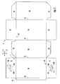
- Fig. 1 is a plan view of the exterior side 1 of a blank, generally indicated at 3, used to form a carton 5 ( Fig. 7 ) according to the exemplary embodiment of the disclosure.
- the carton 5 can be used to house a plurality of articles such as containers C ( Fig. 4 ).
- the carton 5 is sized to house twenty-four containers C in a single layer in a 4x6 arrangement, but it is understood that the carton 5 may be sized and shaped to hold containers of a different or same quantity in more than one layer and/or in different row/column arrangements (e.g., 1x6, 3x6, 2x6x2, 3x4, 3x5, 4x5, 2x9, 2x6, 3x4, etc.).
- the carton 5 includes a first handle, generally indicated at 11 for grasping and carrying the carton at a first end 51 of the carton ( Figs. 5 and 7 ), and a second handle, generally indicated at 111, for grasping and carrying the carton at a second end 53 of the carton.
- the handles 11, 111 are formed from various features in the blank 3.
- the carton blank 3 has a longitudinal axis L1 and a lateral axis L2.
- the blank 3 comprises a top panel 10 foldably connected to a first side panel 20 at a first lateral fold line 21.
- a bottom panel 30 is foldably connected to the first side panel 20 at a second lateral fold line 31.
- a second side panel 40 is foldably connected to the bottom panel 30 at a third lateral fold line 41.
- the blank 3 includes an attachment flap 50 foldably connected to the top panel 10 at a fourth lateral fold line 52.
- the top panel 10 is foldably connected to a first top end flap 12 and a second top end flap 14.
- the first side panel 20 is foldably connected to a first side end flap 22 and a second side end flap 24.
- the bottom panel 30 is foldably connected to a first bottom end flap 32 and a second bottom end flap 34.
- the second side panel 40 is foldably connected to a first side end flap 42 and a second side end flap 44.
- the top and bottom end flaps 12, 32 and side end flaps 22, 42 extend along a first marginal area of the blank 3, and are foldably connected at a first longitudinal fold line 62 that extends along the length of the blank.
- the top and bottom end flaps 14, 34 and side end flaps 24, 44 extend along a second marginal area of the blank 3, and are foldably connected at a second longitudinal fold line 64 that also extends along the length of the blank.
- the longitudinal fold lines 62, 64 may be, for example, substantially straight, or offset at one or more locations to account for blank thickness or for other factors.
- the features that form the first handle 11 of the carton 5 include an elongate handle flap 131 formed in the top end flap 12 and foldably attached to the top end flap at a handle fold line 133.
- the features of handle 11 include an elongate opening 136 adjacent the handle flap 131.
- the second handle 111 is formed from features that are substantially similar to the features that form the first handle 11.
- the second handle 111 includes an elongate handle flap 137 foldably connected to the top end flap 14 at a handle fold line 139.
- An elongate opening 138 in the top end flap 14 is adjacent the handle flap 137.
- the second handle 111 could have different features than the first handle without departing from the disclosure. Further, the second handle 111 can be omitted without departing from the disclosure.
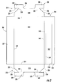
- Fig. 2 illustrates an insert blank 203 used to form a reinforcing insert 205 ( Figs. 4 and 5 ) for use in the carton 5.
- the insert blank 203 includes a central panel 206 and two reinforcing end flaps 212, 214 respectively foldably connected to the central panel 206 at opposite ends of the central panel.
- a first fold line 213 connects the first reinforcing end flap 212 at the first end of the insert blank 203.
- a second fold line 215 connects the second reinforcing end flap 214 at the second end of the insert blank 203.
- the reinforcing end flap 212 includes a base portion 218 at a respective end edge of the central panel 206 and a distal portion 221 foldably connected to the base portion.
- the distal portion 221 includes a U-shaped notch 225 and two tabs 227, 229 each extending laterally outward from the U-shaped notch.
- the tabs 227, 229 are foldably connected to the base portion 218 at respective fold lines 231, 233 extending laterally outward from the U-shaped notch.
- the second reinforcing end flap 214 is similarly shaped as the first reinforcing end flap 212 having a base portion 220, a distal portion 223 with a U-shaped notch 226, tabs 228, 230, and fold lines 232, 234.
- the reinforcing end flap 212 can include two oblique edges 235 defining a portion of the base portion 218 and extending into the respective tabs 227, 229.
- the oblique edges 235 intersect the respective fold lines 231, 233, and a lateral edge 236 of each respective tab 227, 229 extends from an end of each oblique edge 235.
- the reinforcing end flap 214 also can include two oblique edges 235 defining a portion of the base portion 220 and extending to a lateral edge 236 of the respective tabs 228, 230.
- the reinforcing end flaps 212, 214 can be otherwise shaped, configured, arranged, and/or disposed without departing from this disclosure.
- the insert blank 203 includes a first side flap 237 foldably connected to the central panel 206 at a longitudinal fold line 239 and a second side flap 241 foldably connected to the central panel at a longitudinal fold line 243.
- the second side flap 241 includes a first portion 245 that is adjacent the central panel 206, a second portion 247 foldably connected to the first portion at a longitudinal fold line 249, and a third portion 251 foldably connected to the second portion 247 at a longitudinal fold line 253.
- Each of the first portion 245, second portion 247, and third portion 251 is independently positionable at respective fold lines 243, 249, 253.
- the second side flap 241 could be similar to the first side flap 237 in that the second flap could be free of fold lines 249, 253 without departing from the disclosure.
- the insert 205 can be otherwise configured, arranged, shaped, and/or disposed without departing from this disclosure.
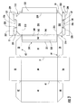
- the carton 5 may be assembled by initially adhering the insert blank 203 to the top panel 10 of the carton blank 3.
- the insert blank 203 is positioned on the carton blank 3 so that the central panel 206 is in generally face-to-face contact with the top panel 10.
- the interior surface of the insert blank 203 is in contact with the interior surface of the carton blank 3.
- the insert blank 203 is sized so that the fold lines 213, 215 connecting the reinforcing end flaps 212, 214 are spaced laterally inward from the fold lines 62, 64 connecting the top end flaps 12, 14 to respective ends of the top panel 10.
- the insert blank 203 is positioned relative to the top panel 10 so that the tabs 227, 229 are adjacent handle flap 131 and the U-shaped notch 225 generally frames the handle flap 131. Similarly, the tabs 228, 230 are adjacent handle flap 137 and the U-shaped notch 226 generally frames the handle flap 137.
- the central panel 206 of the insert blank 203 can be at least partially adhesively secured to the top panel 10 of the carton blank 3.
- the carton blank 3 with insert blank 203 can be further erected into the carton 5 by folding along fold lines 21, 31, 41, and 52 and adhering the attachment flap 50 to the second side panel 40 to form a sleeve.
- the carton blank 3 may be otherwise configured to have multiple top panels, multiple bottom panels, multiple side panels, or combinations thereof without departing from the scope of this disclosure.
- the first end 51 of the carton 5 is closed by respectively overlapping and adhering the side end flaps 22, 42 and the top and bottom end flaps 12, 32.
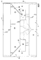
- the end flaps 12, 22, 32, 42 are closed in a manner so that the tabs 227, 229 of the first reinforcing end flap 212 of the insert blank 203 at least partially overlap a respective side end flap 22, 42.
- the first reinforcing end flap 212 is downwardly folded as shown in Fig. 4 , prior to the downwardly folding of the top end flap 12 to close the first end 51 of the carton 5. Accordingly, portions of the tabs 227, 229 are sandwiched between the top end flap 12 and the respective side end flaps 22, 42.
- the tabs 227, 229 are in face-to-face contact with the interior surface of the top end flap 12, and portions of the tabs 227, 229 are in face-to-face contact with the exterior surface of the respective side end flaps 22, 42.
- the positioning of the tabs 227, 229 can help provide extra reinforcement of the handle 11 and the closed end 51.
- the second end 53 of the carton 5 is closed in a similar manner as the first end 51 by respectively overlapping and adhering the side end flaps 24, 44, the top and bottom end flaps 14, 34, and the reinforcing end flap 214 of the insert blank 203.
- the ends 51, 53 of the carton 5 can be otherwise closed without departing from the disclosure.
- the containers C can be loaded into the carton 5 before closing either end or after closing the first end 51 or the second end 53.
- the interior space 301 of the carton 5 is defined by four inwardly tapered surfaces that angle downward from the top panel 10.
- the tapered surface formed by the base portion 220 of the second reinforcing end flap 214 is not visible in Fig. 5 , but it is configured similarly to the base portion 218 of the first reinforcing end flap 212.
- the four inwardly tapered surfaces contact the top portions of the containers C (e.g., bottles) in the carton 5 to restrain the top portions of the containers and to prevent the containers from movement that can cause the containers to break.
- the four inwardly tapered surfaces comprise the two base portions 218, 220 of respective reinforcing end flaps 212, 214 and the two side flaps 237, 241 of the insert 205.
- the base portions 218, 220 extend at an angle from the central panel 206 to the overlapped end flaps forming the closed ends 51, 53, and the two side flaps 237, 241 extend at an angle from the central panel 206 at the top of the carton 5 to the respective side panels 40, 20.
- the base portions 218, 220 can contact the tops of containers that are adjacent respective ends 51, 53 of the carton, and the side flaps 237, 241 can contact the tops of containers that are adjacent the side panels 40, 20.
- the handle 11 can be used to grasp the carton 5 by pressing against the elongate handle flap 131 to enlarge the handle opening 136 in the closed first end 51 of the carton 5.
- the handle 111 can be used to grasp the carton 5 at the closed second end 53.
- the base portions 218, 220 can also provide reinforcement features for the handle 11, 111.
- the base portion 218 of the first reinforcing end flap 212 can provide an extra layer of material above the handle opening 136 in the top end flap 12. Accordingly, the base portion 218, the top end flap 12, and a portion of the top panel 10 form a reinforcing portion or gripping portion 303 above the handle 11 that has a generally triangular cross-sectional shape.
- the gripping portion 303 can comprise the inwardly folded handle flap 131 that can be placed in face-to-face contact with base portion 218 of the first reinforcing end flap 212.
- the second end 53 of the carton 5 can include a gripping portion (not shown) above the handle 111 formed by the base portion 220 of the second reinforcing end flap 214, the second top end flap 14, and a portion of the top panel 10.
- the carton 5 could have various dispenser features and dispensers that provide access to the containers C in the carton without departing from the disclosure.
- the side panels 20, 40 of the carton 5 are generally perpendicular to the bottom panel 30 and top panel 10, but the carton could be otherwise shaped without departing from the disclosure.
- the insert 205 of the carton 5 provides internal bracing of the containers C at the side panels 20, 40 and ends 51, 53.
- the blanks according to the present disclosure can be, for example, formed from coated paperboard and similar materials.
- the interior and/or exterior sides of the blanks can be coated with a clay coating.
- the clay coating may then be printed over with product, advertising, price coding, and other information or images.
- the blanks may then be coated with a varnish to protect any information printed on the blank.
- the blanks may also be coated with, for example, a moisture barrier layer, on either or both sides of the blank.
- the blanks may be constructed of paperboard of a caliper such that it is heavier and more rigid than ordinary paper.
- the blanks can also be constructed of other materials, such as cardboard, hard paper, or any other material having properties suitable for enabling the carton to function at least generally as described herein.
- the blanks can also be laminated or coated with one or more sheet-like materials at selected panels or panel sections.
- a fold line can be any substantially linear, although not necessarily straight, form of weakening that facilitates folding therealong. More specifically, but not for the purpose of narrowing the scope of the present disclosure, fold lines include: a score line, such as lines formed with a blunt scoring knife, or the like, which creates a crushed portion in the material along the desired line of weakness; a cut that extends partially into a material along the desired line of weakness, and/or a series of cuts that extend partially into and/or completely through the material along the desired line of weakness; and various combinations of these features.
- a score line such as lines formed with a blunt scoring knife, or the like, which creates a crushed portion in the material along the desired line of weakness
- a cut that extends partially into a material along the desired line of weakness, and/or a series of cuts that extend partially into and/or completely through the material along the desired line of weakness; and various combinations of these features.
- the above embodiments may be described as having one or more panels adhered together by glue during erection of the carton embodiments.
- glue is intended to encompass all manner of adhesives commonly used to secure carton panels in place.
Landscapes
- Engineering & Computer Science (AREA)
- Mechanical Engineering (AREA)
- Cartons (AREA)
- Packages (AREA)
Claims (26)
- Schachtel (5) zur Aufnahme mehrerer Behälter (C), wobei die Schachtel Folgendes umfasst:mehrere Flächen, die sich mindestens teilweise um einen Innenraum (301) der Schachtel erstrecken, wobei die mehreren Flächen eine Deckelfläche (10), eine erste Seitenfläche (20), eine Bodenfläche (30) undeine zweite Seitenfläche (40) umfassen;mindestens zwei Endklappen (12, 22, 32, 42, 14, 24, 34, 44), die jeweils faltbar an entsprechenden Flächen der mehreren Flächen angebracht sind, wobei die mindestens zwei Endklappen einander überlappen, um dadurch mindestens teilweise ein geschlossenes Ende (51, 53) der Schachtel (5) zu bilden; undeinen Verstärkungseinsatz (205), der eine mittlere Fläche (206) und mindestens eine verstärkende Endklappe (212, 214) umfasst, wobei die mittlere Fläche (206) mindestens teilweise in dem Innenraum (301) der Schachtel (5) angeordnet ist, und die mindestens eine verstärkende Endklappe (212, 214) einen Fußteil (218, 220) und einen faltbar mit dem Fußteil verbundenen distalen Teil (221, 223) umfasst;dadurch gekennzeichnet, dassder Fußteil (218, 220) sich in einer schrägen Richtung von der mittleren Fläche (206) zum geschlossenen Ende (51, 53) der Schachtel (5) erstreckt, wobei mindestens ein Teil des distalen Teils (221, 223) nach außen von mindestens einer Endklappe der mindestens zwei Endklappen (12, 22, 32, 42, 14, 24, 34, 44) positioniert ist, und der distale Teil (221, 223) mindestens eine Lasche (227, 229, 228, 230) umfasst, die sich zu der ersten Seitenfläche (20) und/oder der zweiten Seitenfläche (40) erstreckt.
- Schachtel (5) nach Anspruch 1, wobei der Verstärkungseinsatz (205) ferner mindestens eine verstärkende Seitenklappe umfasst, die faltbar (237, 241) mit der mittleren Fläche (206) verbunden ist und sich zu der ersten Seitenfläche (20) und/oder der zweiten Seitenfläche (40) in einer schrägen Richtung mit Bezug auf die Deckelfläche (10) erstreckt.
- Schachtel (5) nach Anspruch 1,
wobei jede Endklappe (12, 22, 32, 42, 14, 24, 34, 44) der mindestens zwei Endklappen eine Innenfläche und eine Außenfläche umfasst;
wobei die mindestens zwei Endklappen eine erste seitliche Endklappe (22, 24), die faltbar mit der ersten Seitenfläche (20) verbunden ist, und eine obere Endklappe (12, 14) umfassen, die faltbar mit der Deckelfläche (10) verbunden ist; und
wobei der distale Teil (221, 223) der mindestens einen verstärkenden Endklappe (212, 214) mindestens teilweise in flächigem Kontakt mit der Außenfläche der ersten seitlichen Endklappe (22, 24) und der Innenfläche der oberen Endklappe (12, 14) steht. - Schachtel (5) nach Anspruch 3, wobei die mindestens eine verstärkende Endklappe (212, 214) mindestens eine schräge Kante (235) umfasst, die sich mindestens teilweise zwischen dem distalen Teil (221, 223) der mindestens einen verstärkenden Endklappe (212, 214) und der mittleren Fläche (206) erstreckt.
- Schachtel (5) nach Anspruch 4,
wobei die mindestens eine schräge Kante (235) der mindestens einen verstärkenden Endklappe (212, 214) eine erste schräge Kante (235) und eine gegenüber der ersten schrägen Kante angeordnete zweite schräge Kante (235) umfasst; und
wobei die mindestens eine Lasche (227, 229, 228, 230) des distalen Teils (221, 223) der mindestens einen verstärkenden Endklappe eine erste Lasche (227, 228) und eine zweite Lasche (229, 230) umfasst, wobei die erste Lasche sich zu der ersten Seitenfläche (20) erstreckt, und die zweite Lasche sich zu der zweiten Seitenfläche (40) erstreckt. - Schachtel (5) nach Anspruch 5,
wobei der Fußteil (218, 220) der mindestens einen verstärkenden Endklappe (212, 214) faltbar mit der mittleren Fläche (206) entlang einer ersten Faltlinie (213, 215) verbunden ist, und der distale Teil (221, 223) der mindestens einen verstärkenden Endklappe (212, 214) faltbar mit dem Fußteil (218, 220) der mindestens einen verstärkenden Endklappe entlang einer zweiten Faltlinie (231, 233, 232, 234) verbunden ist, wobei die zweite Faltlinie sich von der ersten schrägen Kante (235) der mindestens einen verstärkenden Endklappe (212, 214) zur zweiten schrägen Kante (235) der mindestens einen verstärkenden Endklappe erstreckt; und
wobei die erste Faltlinie (213, 215) länger als die zweite Faltlinie (231, 233, 232, 234) ist. - Schachtel (5) nach Anspruch 3,
wobei die mindestens zwei Endklappen eine zweite seitliche Endklappe (42, 44) umfassen, die faltbar mit der zweiten Seitenfläche (40) verbunden ist; und wobei der distale Teil (221, 223) der mindestens einen verstärkenden Endklappe (212, 214) mindestens teilweise in flächigem Kontakt mit der Außenfläche der zweiten seitlichen Endklappe (42, 44) steht. - Schachtel (5) nach Anspruch 7, wobei die obere Endklappe (12, 14) eine Handhabe (11, 111) umfasst, und der distale Teil (221, 223) der mindestens einen verstärkenden Endklappe (212, 214) eine Klinke (225, 226) umfasst, die mit der Handhabe (11, 111) in der oberen Endklappe (12, 14) allgemein ausgerichtet ist.
- Schachtel (5) nach Anspruch 8, wobei die Klinke (225, 226) mindestens teilweise durch eine Kante des Fußteils (218, 220) der mindestens einen verstärkenden Endklappe (212, 214) definiert ist, und die Kante des Fußteils nahe einer oberen Kante der Handhabe (11, 111) der oberen Endklappe (12, 14) angeordnet ist.
- Schachtel (5) nach Anspruch 9, wobei mindestens ein Teil des Fußteils (218, 220) der mindestens einen verstärkenden Endklappe (212, 214) und mindestens ein Teil der oberen Endklappe (12, 14) einen keilförmigen Greifteil (303) oberhalb der Handhabe (11, 111) in der oberen Endklappe (12, 14) und der Klinke (225, 226) in dem distalen Teil (221, 223) der mindestens einen verstärkenden Endklappe (212, 214) bilden.
- Schachtel (5) nach Anspruch 3,
wobei das geschlossene Ende (51, 53) der Schachtel (5) ein erstes geschlossenes Ende (51) der Schachtel ist;
wobei die Schachtel (5) ferner ein zweites geschlossenes Ende (53) der Schachtel gegenüber dem ersten geschlossenen Ende (51) der Schachtel umfasst;
wobei die mindestens eine verstärkende Endklappe (212, 214) eine erste verstärkende Endklappe (212) an dem ersten geschlossenen Ende (51) der Schachtel (5) und eine zweite verstärkende Endklappe (214) an dem zweiten geschlossenen Ende (53) der Schachtel umfasst. - Schachtel (5) nach Anspruch 11, wobei der Verstärkungseinsatz (205) ferner eine erste verstärkende Seitenklappe (237) und eine zweite verstärkende Seitenklappe (241) umfasst, die jeweils faltbar mit der mittleren Fläche (206) verbunden sind, wobei die erste verstärkende Seitenklappe (237) sich zu der ersten Seitenfläche (20) in einer schrägen Richtung mit Bezug auf die Deckelfläche (10) erstreckt, und die zweite verstärkende Seitenklappe (241) sich zu der zweiten Seitenfläche (40) in einer schrägen Richtung mit Bezug auf die Deckelfläche (10) erstreckt.
- Schachtel (5) nach Anspruch 3, wobei die mittlere Fläche (206) mindestens teilweise in flächigem Kontakt mit der Deckelfläche (10) steht.
- Schachtel (5) nach Anspruch 1, wobei das geschlossene Ende (51, 53) der Schachtel (5) und die erste Seitenfläche (20) und/oder die zweite Seitenfläche (40) sich allgemein senkrecht zur Deckelfläche (10) erstrecken.
- In Kombination Schachtelzuschnitt (3) und Einsatzzuschnitt (203) zum Bilden einer Schachtel (5) nach einem der Ansprüche 1 bis 14, wobei die Schachtel behältersichernde Merkmale zum Einschränken der Bewegung der Behälter (C) in der Schachtel aufweist, wobei der Schachtelzuschnitt (3) Folgendes umfasst:mehrere Flächen, die eine Deckelfläche (10), eine erste Seitenfläche (20), eine Bodenfläche (30) und eine zweite Seitenfläche (40) umfassen;mindestens zwei Endklappen (12, 22, 32, 42, 14, 24, 34, 44), die jeweils faltbar an entsprechenden Flächen der mehreren Flächen angebracht sind, damit die mindestens zwei Endklappen sich einander überlappen, um dadurch mindestens teilweise ein Ende (51, 53) der aus dem Schachtelzuschnitt (3) und dem Einsatzzuschnitt (203) gebildeten Schachtel (5) zu verschließen; undwobei der Einsatzzuschnitt (203) Folgendes umfasst:eine mittlere Fläche (206) zum mindestens teilweisen Anordnen in dem Innenraum (301) der aus dem Schachtelzuschnitt (3) und dem Einsatzzuschnitt (203) gebildeten Schachtel; undmindestens eine verstärkende Endklappe (212, 214), die einen Fußteil (218, 220) und einen mit dem Fußteil faltbar verbundenen distalen Teil (221, 223) umfasst;dadurch gekennzeichnet, dassder Fußteil derart positioniert werden kann, dass er sich in einer schrägen Richtung von der mittleren Fläche (206) zum geschlossenen Ende (51, 53) der Schachtel (5) erstreckt, wenn die Schachtel aus dem Schachtelzuschnitt (3) und dem Einsatzzuschnitt (203) gebildet ist, undmindestens ein Teil des distalen Teils (221, 223) in flächigem Kontakt mit der Außenfläche von mindestens einer Endklappe der mindestens zwei Endklappen (12, 22, 32, 42, 14, 24, 34, 44) angeordnet sein kann, wenn die Schachtel aus dem Schachtelzuschnitt (3) und dem Einsatzzuschnitt (203) gebildet ist, und der distale Teil (221, 223) mindestens eine Lasche (227, 229, 228, 230) umfasst, die derart positioniert ist, dass sie sich zu der ersten Seitenfläche (20) und/oder der zweiten Seitenfläche (40) erstreckt.
- Kombination nach Anspruch 15, wobei der Verstärkungseinsatz (205) ferner mindestens eine verstärkende Seitenklappe (237, 241) umfasst, die faltbar mit der mittleren Fläche (206) verbunden ist, und der Verstärkungseinsatz (205) derart positioniert ist, dass er sich zu der ersten Seitenfläche (20) und/oder der zweiten Seitenfläche (40) in einer schrägen Richtung mit Bezug auf die Deckelfläche (10) erstreckt, wenn die Schachtel (5) aus dem Schachtelzuschnitt (3) und dem Einsatzzuschnitt (203) gebildet ist.
- Kombination nach Anspruch 15, wobei die mindestens eine verstärkende Endklappe (212, 214) mindestens eine schräge Kante (235) umfasst, die sich mindestens teilweise zwischen dem distalen Teil (221, 223) der mindestens einen verstärkenden Endklappe (212, 214) und der mittleren Fläche (206) erstreckt.
- Kombination nach Anspruch 17,
wobei die mindestens eine schräge Kante (235) der mindestens einen verstärkenden Endklappe (212, 214) eine erste schräge Kante (235) und eine gegenüber der ersten schrägen Kante angeordnete zweite schräge Kante (235) umfasst;
wobei die mindestens eine Lasche (227, 229, 228, 230) des distalen Teils (221, 223) der mindestens einen verstärkenden Endklappe (212, 214) eine erste Lasche (227, 228) und eine zweite Lasche (229, 230) umfasst, wobei die erste Lasche sich zu der ersten Seitenfläche (20) erstreckt, und die zweite Lasche sich zu der zweiten Seitenfläche (40) erstreckt;
wobei der Fußteil (218, 220) der mindestens einen verstärkenden Endklappe (212, 214) faltbar mit der mittleren Fläche (206) entlang einer ersten Faltlinie (213, 215) verbunden ist, und der distale Teil (221, 223) der mindestens einen verstärkenden Endklappe (212, 214) faltbar mit dem Fußteil (218, 220) der mindestens einen verstärkenden Endklappe (212, 214) entlang einer zweiten Faltlinie (231, 233, 232, 234) verbunden ist, wobei die zweite Faltlinie sich von der ersten schrägen Kante (235) der mindestens einen verstärkenden Endklappe (212, 214) zu der zweiten schrägen Kante (235) der mindestens einen verstärkenden Endklappe erstreckt; und
wobei die erste Faltlinie (213, 215) länger als die zweite Faltlinie (231, 233, 232, 234) ist. - Kombination nach Anspruch 15,
wobei jede Endklappe der mindestens zwei Endklappen (12, 22, 32, 42, 14, 24, 34, 44) eine Innenfläche und eine Außenfläche umfasst;
wobei die mindestens zwei Endklappen eine erste seitliche Endklappe (22, 24), die faltbar mit der ersten Seitenfläche (20) verbunden ist, und eine obere Endklappe (12, 14) umfassen, die faltbar mit der Deckelfläche (10) verbunden ist;
wobei der distale Teil (221, 223) der mindestens einen verstärkenden Endklappe (212, 214) mindestens teilweise in flächigem Kontakt mit der Außenfläche der ersten seitlichen Endklappe (22, 24) und der Innenfläche der oberen Endklappe (12, 14) angeordnet ist, wenn die Schachtel (5) aus dem Schachtelzuschnitt (3) und dem Einsatzzuschnitt (203) gebildet ist;
wobei die mindestens zwei Endklappen eine zweite seitliche Endklappe (42, 44) umfasst, die faltbar mit der zweiten Seitenfläche (40) verbunden ist; und
wobei der distale Teil (221, 223) der mindestens einen verstärkenden Endklappe (212, 214) mindestens teilweise in flächigem Kontakt mit der Außenfläche der zweiten seitlichen Endklappe (42, 44) angeordnet ist, wenn die Schachtel (5) aus dem Schachtelzuschnitt (3) und dem Einsatzzuschnitt (203) gebildet ist. - Kombination nach Anspruch 19, wobei die obere Endklappe (12, 14) eine Handhabe (11, 111) umfasst, und der distale Teil (221, 223) der mindestens einen verstärkenden Endklappe (212, 214) eine Klinke (225, 226) umfasst, die mit der Handhabe (11, 111) in der oberen Endklappe (12, 14) allgemein ausgerichtet ist, wenn die Schachtel (5) aus dem Schachtelzuschnitt (3) und dem Einsatzzuschnitt (203) gebildet ist, wobei die Klinke (225, 226) mindestens teilweise durch eine Kante des Fußteils (218, 220) der mindestens einen verstärkenden Endklappe (212, 214) definiert ist, und die Kante des Fußteils (218, 220) nahe einer oberen Kante der Handhabe (11, 111) der oberen Endklappe (12, 14) angeordnet ist, wenn die Schachtel (5) aus dem Schachtelzuschnitt (3) und dem Einsatzzuschnitt (203) gebildet ist.
- Kombination nach Anspruch 19,
wobei die mindestens eine verstärkende Endklappe (212, 214) eine erste verstärkende Endklappe (212) und eine entgegengesetzte zweite verstärkende Endklappe (214) umfasst, wobei jede der ersten verstärkenden Endklappe und der zweiten verstärkenden Endklappe faltbar mit der mittleren Fläche (206) verbunden ist; und
wobei der Verstärkungseinsatz (205) ferner eine erste verstärkende Seitenklappe (237) und eine entgegengesetzte zweite verstärkende Seitenklappe (241) umfasst, wobei jede der ersten verstärkenden Seitenklappe (237) und der zweiten verstärkenden Seitenklappe (241) faltbar mit der mittleren Fläche (206) verbunden ist. - Verfahren zum Bilden einer Schachtel (5) nach einem der Ansprüche 1 bis 14, welches Folgendes umfasst:Erhalten eines Schachtelzuschnitts (3) mit mehreren Flächen, die eine Deckelfläche (10), eine erste Seitenfläche (20), eine Bodenfläche (30) und eine zweite Seitenfläche (40) umfassen, und wobei mindestens zwei Endklappen (12, 22, 32, 42, 14, 24, 34, 44) jeweils faltbar an entsprechenden Flächen der mehreren Flächen angebracht sind;Erhalten eines Verstärkungseinsatzes (203) mit einer mittleren Fläche (206) und mindestens einer verstärkenden Endklappe (212, 214), wobei die mindestens eine verstärkende Endklappe einen Fußteil (218, 220) und einen distalen Teil (221, 223) umfasst, der faltbar mit dem Fußteil (218, 220) verbunden ist, wobei der distale Teil (221, 223) mindestens eine Lasche (227, 229, 228, 230) umfasst;Positionieren des Verstärkungseinsatzes (203) relativ zum Schachtelzuschnitt (3) derart, dass die mittlere Fläche (206) mindestens einen Teil der Deckelfläche (10) überlappt;Bilden eines Innenraums (301) der Schachtel (5), der mindestens teilweise durch die mehreren Flächen (10, 20, 30, 40) definiert ist, wobei die mittlere Fläche (206) mindestens teilweise innerhalb des Innenraums (301) der Schachtel (5) angeordnet wird, wobei das Bilden des Innenraums (301) der Schachtel (5) das Bilden einer Hülse mit offenem Ende umfasst;Positionieren des Fußteils (218, 220) der mindestens einen verstärkenden Endklappe (212, 214) derart, dass er sich in einer schrägen Richtung von der mittleren Fläche (206) zu einem Ende der Hülse mit offenem Ende erstreckt;Positionieren der mindestens zwei Endklappen (12, 22, 32, 42, 14, 24, 34, 44) und des distalen Teils (221, 223) der mindestens einen verstärkenden Endklappe (212, 214) derart, dass ein Ende (51, 53) der Hülse mit offenem Ende mindestens teilweise verschlossen wird, wobei mindestens ein Teil des distalen Teils (221, 223) nach außen von mindestens einer Endklappe der mindestens zwei Endklappen (12, 22, 32, 42, 14, 24, 34, 44) positioniert wird, und die mindestens eine Lasche (227, 229, 228, 230) des distalen Teils (221, 223) sich zu der ersten Seitenfläche (20) und/oder der zweiten Seitenfläche (40) erstreckt.
- Verfahren nach Anspruch 22,
wobei der Verstärkungseinsatz (203) ferner mindestens eine verstärkende Seitenklappe (237, 241) umfasst, die faltbar mit der mittleren Fläche (206) verbunden ist; und
wobei das Verfahren ferner das Positionieren der mindestens einen verstärkenden Seitenklappe (237, 241) derart umfasst, dass sie sich zu der ersten Seitenfläche (20) und/oder der zweiten Seitenfläche (40) in einer schrägen Richtung mit Bezug auf die Deckelfläche (10) erstreckt. - Verfahren nach Anspruch 22,
wobei jede Endklappe der mindestens zwei Endklappen (12, 22, 32, 42, 14, 24, 34, 44) eine Innenfläche und eine Außenfläche umfasst;
wobei die mindestens zwei Endklappen (12, 22, 32, 42, 14, 24, 34, 44) eine erste seitliche Endklappe (22, 24), die faltbar mit der ersten Seitenfläche (20) verbunden ist, und eine obere Endklappe (12, 14) umfassen, die faltbar mit der Deckelfläche (10) verbunden ist; und
wobei das Positionieren der mindestens zwei Endklappen (12, 22, 32, 42, 14, 24, 34, 44) und des distalen Teils (221, 223) der mindestens einen verstärkenden Endklappe (212, 214) das Positionieren des distalen Teils (221, 223) der mindestens einen verstärkenden Endklappe (212, 214) mindestens teilweise in flächigem Kontakt mit der Außenfläche der ersten seitlichen Endklappe (22, 24) und der Innenfläche der oberen Endklappe (12, 14) umfasst. - Verfahren nach Anspruch 22,
wobei die obere Endklappe (12, 14) eine Handhabe (11, 111) umfasst, und der distale Teil (221, 223) der mindestens einen verstärkenden Endklappe (212, 214) eine Klinke (225, 226) umfasst;
wobei das Positionieren der mindestens zwei Endklappen (12, 22, 32, 42, 14, 24, 34, 44) und des distalen Teils (221, 223) der mindestens einen verstärkenden Endklappe (212, 214) das allgemeine Ausrichten der Klinke (225, 226) des distalen Teils (221, 223) der mindestens einen verstärkenden Endklappe (212, 214) mit der Handhabe (11, 111) in der oberen Endklappe (12, 14) umfasst; und
wobei das Positionieren der mindestens zwei Endklappen (12, 22, 32, 42, 14, 24, 34, 44) und des distalen Teils (221, 223) der mindestens einen verstärkenden Endklappe (212, 214) das Bilden eines keilförmigen Greifteils (303) oberhalb der Handhabe (11, 111) in der oberen Endklappe (12, 14) und der Klinke (225, 226) in dem distalen Teil (221, 223) der mindestens einen verstärkenden Endklappe (212, 214) umfasst, wobei der Greifteil mindestens einen Teil des Fußteils (218, 220) der mindestens einen verstärkenden Endklappe (212, 214) und mindestens einen Teil der oberen Endklappe (12, 14) umfasst. - Verfahren nach Anspruch 22,
wobei das Bilden des Innenraums (301) der Schachtel (5) das Positionieren der ersten Seitenfläche (20) und/oder der zweiten Seitenfläche (40) derart umfasst, dass sie allgemein senkrecht zur Deckelfläche (10) angeordnet sind; und
wobei das Positionieren der mindestens zwei Endklappen (12, 22, 32, 42, 14, 24, 34, 44) und des distalen Teils (221, 223) der mindestens einen verstärkenden Endklappe (212, 214) das Positionieren der mindestens zwei Endklappen (12, 22, 32, 42, 14, 24, 34, 44) derart umfasst, dass sie allgemein senkrecht zur Deckelfläche (10) angeordnet sind.
Applications Claiming Priority (2)
| Application Number | Priority Date | Filing Date | Title |
|---|---|---|---|
| US39895610P | 2010-07-02 | 2010-07-02 | |
| PCT/US2011/042483 WO2012003251A2 (en) | 2010-07-02 | 2011-06-30 | Carton with insert |
Publications (3)
| Publication Number | Publication Date |
|---|---|
| EP2588385A2 EP2588385A2 (de) | 2013-05-08 |
| EP2588385A4 EP2588385A4 (de) | 2015-07-29 |
| EP2588385B1 true EP2588385B1 (de) | 2016-11-23 |
Family
ID=45402642
Family Applications (1)
| Application Number | Title | Priority Date | Filing Date |
|---|---|---|---|
| EP11801373.9A Not-in-force EP2588385B1 (de) | 2010-07-02 | 2011-06-30 | Karton mit einsatz |
Country Status (5)
| Country | Link |
|---|---|
| US (2) | US8496109B2 (de) |
| EP (1) | EP2588385B1 (de) |
| CA (1) | CA2803008C (de) |
| ES (1) | ES2612480T3 (de) |
| WO (1) | WO2012003251A2 (de) |
Cited By (1)
| Publication number | Priority date | Publication date | Assignee | Title |
|---|---|---|---|---|
| EP4512729A1 (de) * | 2023-08-23 | 2025-02-26 | The Procter & Gamble Company | Behälterzuschnitte, verfahren zum falten derselben und verwendung eines so erhaltenen behälters |
Families Citing this family (16)
| Publication number | Priority date | Publication date | Assignee | Title |
|---|---|---|---|---|
| NZ631247A (en) * | 2012-04-27 | 2016-06-24 | Graphic Packaging Int Inc | Carton with insert |
| ES2620435T3 (es) * | 2012-07-17 | 2017-06-28 | Graphic Packaging International, Inc. | Cajas de cartón con inserto |
| WO2014186267A1 (en) | 2013-05-13 | 2014-11-20 | Graphic Packaging International, Inc. | Carton with insert |
| NZ713712A (en) | 2013-05-13 | 2018-02-23 | Graphic Packaging Int Llc | Carton with article protection features |
| NZ719459A (en) * | 2013-12-10 | 2018-02-23 | Graphic Packaging Int Llc | Carton with article protection features |
| EP3110704B1 (de) | 2014-02-28 | 2018-09-12 | Graphic Packaging International, LLC | Karton mit artikelschutzfunktionen |
| CN107148388B (zh) | 2014-10-30 | 2019-08-16 | 印刷包装国际有限责任公司 | 具有手柄的纸箱 |
| US11117704B2 (en) | 2019-11-11 | 2021-09-14 | Pratt Corrugated Holdings, Inc. | Beverage box |
| US11472596B2 (en) | 2020-06-17 | 2022-10-18 | Pratt Corrugated Holdings, Inc. | One- and two-pack beverage box |
| USD1007300S1 (en) | 2020-09-30 | 2023-12-12 | Pratt Corrugated Holdings, Inc. | Two-cell beverage box |
| USD997739S1 (en) | 2020-09-30 | 2023-09-05 | Pratt Corrugated Holdings, Inc. | Six-cell beverage box with top flaps |
| USD1026667S1 (en) | 2020-09-30 | 2024-05-14 | Pratt Corrugated Holdings, Inc. | One-cell beverage box |
| USD997740S1 (en) | 2020-09-30 | 2023-09-05 | Pratt Corrugated Holdings, Inc. | Three-cell beverage box |
| USD997741S1 (en) * | 2020-09-30 | 2023-09-05 | Pratt Corrugated Holdings, Inc. | Six-cell beverage box |
| US11820569B2 (en) | 2021-03-11 | 2023-11-21 | Graphic Packaging International, Llc | Carrier for containers |
| USD1036990S1 (en) | 2022-02-03 | 2024-07-30 | Graphic Packaging International, Llc | Carrier for containers |
Family Cites Families (14)
| Publication number | Priority date | Publication date | Assignee | Title |
|---|---|---|---|---|
| US5224919A (en) * | 1990-09-07 | 1993-07-06 | Graphic Packaging Corporation | Method and apparatus for attaching insert panels to carton blanks |
| DE29815677U1 (de) * | 1998-09-01 | 1998-11-19 | Fcp Europa Carton Faltschachte | Behälterträger |
| US6968992B2 (en) * | 2003-10-24 | 2005-11-29 | Graphic Packaging International, Inc. | Handle and top handle reinforcement for a paperboard carton |
| US20070007325A1 (en) * | 2005-07-07 | 2007-01-11 | Tsugihiko Suzuki | Carton with handle reinforcement structure |
| US20080128479A1 (en) * | 2005-09-21 | 2008-06-05 | Aaron Bates | Carton With Handle-Reinforcement Insert |
| AU2006311674B2 (en) * | 2005-11-08 | 2010-12-16 | Graphic Packaging International, Inc. | Carton with reinforced handle |
| US20080023535A1 (en) * | 2006-04-13 | 2008-01-31 | Holley Jr John M | Carton with article dispenser formed in a composite wall |
| EP2313326A1 (de) * | 2008-08-22 | 2011-04-27 | Graphic Packaging International, Inc. | Karton mit einsatz |
| EP2408686B1 (de) * | 2009-03-17 | 2014-06-25 | Graphic Packaging International, Inc. | Karton mit verstärktem deckel |
| WO2011008854A2 (en) * | 2009-07-14 | 2011-01-20 | Graphic Packaging International, Inc. | Carton with insert |
| CA2771898C (en) * | 2009-08-28 | 2014-10-14 | Graphic Packaging International, Inc. | Carton with insert |
| EP2616356B1 (de) * | 2010-09-17 | 2016-03-16 | Graphic Packaging International, Inc. | Karton mit einsatz |
| CA2813422C (en) * | 2010-10-15 | 2015-02-03 | Graphic Packaging International, Inc. | Carton with reinforced top panel |
| NZ713712A (en) * | 2013-05-13 | 2018-02-23 | Graphic Packaging Int Llc | Carton with article protection features |
-
2011
- 2011-06-30 EP EP11801373.9A patent/EP2588385B1/de not_active Not-in-force
- 2011-06-30 CA CA2803008A patent/CA2803008C/en not_active Expired - Fee Related
- 2011-06-30 WO PCT/US2011/042483 patent/WO2012003251A2/en not_active Ceased
- 2011-06-30 ES ES11801373.9T patent/ES2612480T3/es active Active
-
2012
- 2012-12-19 US US13/719,662 patent/US8496109B2/en not_active Expired - Fee Related
-
2013
- 2013-06-20 US US13/922,270 patent/US9174763B2/en active Active
Cited By (2)
| Publication number | Priority date | Publication date | Assignee | Title |
|---|---|---|---|---|
| EP4512729A1 (de) * | 2023-08-23 | 2025-02-26 | The Procter & Gamble Company | Behälterzuschnitte, verfahren zum falten derselben und verwendung eines so erhaltenen behälters |
| WO2025042641A1 (en) * | 2023-08-23 | 2025-02-27 | The Procter & Gamble Company | Container blanks, methods of folding the same, and uses of a container thereby obtained |
Also Published As
| Publication number | Publication date |
|---|---|
| EP2588385A4 (de) | 2015-07-29 |
| EP2588385A2 (de) | 2013-05-08 |
| US20130277260A1 (en) | 2013-10-24 |
| WO2012003251A2 (en) | 2012-01-05 |
| CA2803008A1 (en) | 2012-01-05 |
| US20130118942A1 (en) | 2013-05-16 |
| WO2012003251A3 (en) | 2012-04-12 |
| CA2803008C (en) | 2014-10-07 |
| US8496109B2 (en) | 2013-07-30 |
| ES2612480T3 (es) | 2017-05-17 |
| US9174763B2 (en) | 2015-11-03 |
Similar Documents
| Publication | Publication Date | Title |
|---|---|---|
| CA2803008C (en) | Carton with insert | |
| EP2576380B1 (de) | Karton mit einsatz | |
| EP2616356B1 (de) | Karton mit einsatz | |
| EP2874905B1 (de) | Karton mit einsatz | |
| EP2841353B1 (de) | Karton mit einsatz | |
| EP2627575B1 (de) | Karton mit verstärktem deckel | |
| EP2326568B1 (de) | Schachtel mit verstärktem griff | |
| EP2408686B1 (de) | Karton mit verstärktem deckel | |
| EP2379421B1 (de) | Karton mit verstärkungseinsatz | |
| CA2730092A1 (en) | Carton with insert | |
| EP2454168A2 (de) | Karton mit einsatz | |
| EP2996958B1 (de) | Karton mit einsatz | |
| CA2868840A1 (en) | Carton with handle | |
| WO2011142897A2 (en) | Carton with handle |
Legal Events
| Date | Code | Title | Description |
|---|---|---|---|
| PUAI | Public reference made under article 153(3) epc to a published international application that has entered the european phase |
Free format text: ORIGINAL CODE: 0009012 |
|
| 17P | Request for examination filed |
Effective date: 20130110 |
|
| AK | Designated contracting states |
Kind code of ref document: A2 Designated state(s): AL AT BE BG CH CY CZ DE DK EE ES FI FR GB GR HR HU IE IS IT LI LT LU LV MC MK MT NL NO PL PT RO RS SE SI SK SM TR |
|
| DAX | Request for extension of the european patent (deleted) | ||
| A4 | Supplementary search report drawn up and despatched |
Effective date: 20150630 |
|
| RIC1 | Information provided on ipc code assigned before grant |
Ipc: B65D 5/44 20060101AFI20150624BHEP |
|
| REG | Reference to a national code |
Ref country code: DE Ref legal event code: R079 Ref document number: 602011032755 Country of ref document: DE Free format text: PREVIOUS MAIN CLASS: B65D0071120000 Ipc: B65D0005020000 |
|
| RIC1 | Information provided on ipc code assigned before grant |
Ipc: B31B 1/26 20060101ALN20160502BHEP Ipc: B31B 1/90 20060101ALN20160502BHEP Ipc: B65D 5/02 20060101AFI20160502BHEP Ipc: B65D 5/468 20060101ALI20160502BHEP Ipc: B65D 5/44 20060101ALI20160502BHEP |
|
| GRAP | Despatch of communication of intention to grant a patent |
Free format text: ORIGINAL CODE: EPIDOSNIGR1 |
|
| INTG | Intention to grant announced |
Effective date: 20160620 |
|
| GRAS | Grant fee paid |
Free format text: ORIGINAL CODE: EPIDOSNIGR3 |
|
| GRAA | (expected) grant |
Free format text: ORIGINAL CODE: 0009210 |
|
| AK | Designated contracting states |
Kind code of ref document: B1 Designated state(s): AL AT BE BG CH CY CZ DE DK EE ES FI FR GB GR HR HU IE IS IT LI LT LU LV MC MK MT NL NO PL PT RO RS SE SI SK SM TR |
|
| REG | Reference to a national code |
Ref country code: GB Ref legal event code: FG4D |
|
| REG | Reference to a national code |
Ref country code: CH Ref legal event code: EP |
|
| REG | Reference to a national code |
Ref country code: IE Ref legal event code: FG4D |
|
| REG | Reference to a national code |
Ref country code: AT Ref legal event code: REF Ref document number: 847638 Country of ref document: AT Kind code of ref document: T Effective date: 20161215 |
|
| REG | Reference to a national code |
Ref country code: DE Ref legal event code: R096 Ref document number: 602011032755 Country of ref document: DE |
|
| REG | Reference to a national code |
Ref country code: NL Ref legal event code: FP |
|
| PG25 | Lapsed in a contracting state [announced via postgrant information from national office to epo] |
Ref country code: LV Free format text: LAPSE BECAUSE OF FAILURE TO SUBMIT A TRANSLATION OF THE DESCRIPTION OR TO PAY THE FEE WITHIN THE PRESCRIBED TIME-LIMIT Effective date: 20161123 |
|
| REG | Reference to a national code |
Ref country code: LT Ref legal event code: MG4D |
|
| REG | Reference to a national code |
Ref country code: AT Ref legal event code: MK05 Ref document number: 847638 Country of ref document: AT Kind code of ref document: T Effective date: 20161123 |
|
| PG25 | Lapsed in a contracting state [announced via postgrant information from national office to epo] |
Ref country code: NO Free format text: LAPSE BECAUSE OF FAILURE TO SUBMIT A TRANSLATION OF THE DESCRIPTION OR TO PAY THE FEE WITHIN THE PRESCRIBED TIME-LIMIT Effective date: 20170223 Ref country code: LT Free format text: LAPSE BECAUSE OF FAILURE TO SUBMIT A TRANSLATION OF THE DESCRIPTION OR TO PAY THE FEE WITHIN THE PRESCRIBED TIME-LIMIT Effective date: 20161123 Ref country code: GR Free format text: LAPSE BECAUSE OF FAILURE TO SUBMIT A TRANSLATION OF THE DESCRIPTION OR TO PAY THE FEE WITHIN THE PRESCRIBED TIME-LIMIT Effective date: 20170224 Ref country code: SE Free format text: LAPSE BECAUSE OF FAILURE TO SUBMIT A TRANSLATION OF THE DESCRIPTION OR TO PAY THE FEE WITHIN THE PRESCRIBED TIME-LIMIT Effective date: 20161123 |
|
| REG | Reference to a national code |
Ref country code: ES Ref legal event code: FG2A Ref document number: 2612480 Country of ref document: ES Kind code of ref document: T3 Effective date: 20170517 |
|
| PG25 | Lapsed in a contracting state [announced via postgrant information from national office to epo] |
Ref country code: RS Free format text: LAPSE BECAUSE OF FAILURE TO SUBMIT A TRANSLATION OF THE DESCRIPTION OR TO PAY THE FEE WITHIN THE PRESCRIBED TIME-LIMIT Effective date: 20161123 Ref country code: PT Free format text: LAPSE BECAUSE OF FAILURE TO SUBMIT A TRANSLATION OF THE DESCRIPTION OR TO PAY THE FEE WITHIN THE PRESCRIBED TIME-LIMIT Effective date: 20170323 Ref country code: AT Free format text: LAPSE BECAUSE OF FAILURE TO SUBMIT A TRANSLATION OF THE DESCRIPTION OR TO PAY THE FEE WITHIN THE PRESCRIBED TIME-LIMIT Effective date: 20161123 Ref country code: FI Free format text: LAPSE BECAUSE OF FAILURE TO SUBMIT A TRANSLATION OF THE DESCRIPTION OR TO PAY THE FEE WITHIN THE PRESCRIBED TIME-LIMIT Effective date: 20161123 Ref country code: PL Free format text: LAPSE BECAUSE OF FAILURE TO SUBMIT A TRANSLATION OF THE DESCRIPTION OR TO PAY THE FEE WITHIN THE PRESCRIBED TIME-LIMIT Effective date: 20161123 Ref country code: HR Free format text: LAPSE BECAUSE OF FAILURE TO SUBMIT A TRANSLATION OF THE DESCRIPTION OR TO PAY THE FEE WITHIN THE PRESCRIBED TIME-LIMIT Effective date: 20161123 |
|
| PG25 | Lapsed in a contracting state [announced via postgrant information from national office to epo] |
Ref country code: SK Free format text: LAPSE BECAUSE OF FAILURE TO SUBMIT A TRANSLATION OF THE DESCRIPTION OR TO PAY THE FEE WITHIN THE PRESCRIBED TIME-LIMIT Effective date: 20161123 Ref country code: DK Free format text: LAPSE BECAUSE OF FAILURE TO SUBMIT A TRANSLATION OF THE DESCRIPTION OR TO PAY THE FEE WITHIN THE PRESCRIBED TIME-LIMIT Effective date: 20161123 Ref country code: RO Free format text: LAPSE BECAUSE OF FAILURE TO SUBMIT A TRANSLATION OF THE DESCRIPTION OR TO PAY THE FEE WITHIN THE PRESCRIBED TIME-LIMIT Effective date: 20161123 Ref country code: EE Free format text: LAPSE BECAUSE OF FAILURE TO SUBMIT A TRANSLATION OF THE DESCRIPTION OR TO PAY THE FEE WITHIN THE PRESCRIBED TIME-LIMIT Effective date: 20161123 Ref country code: CZ Free format text: LAPSE BECAUSE OF FAILURE TO SUBMIT A TRANSLATION OF THE DESCRIPTION OR TO PAY THE FEE WITHIN THE PRESCRIBED TIME-LIMIT Effective date: 20161123 |
|
| REG | Reference to a national code |
Ref country code: DE Ref legal event code: R097 Ref document number: 602011032755 Country of ref document: DE |
|
| PG25 | Lapsed in a contracting state [announced via postgrant information from national office to epo] |
Ref country code: BG Free format text: LAPSE BECAUSE OF FAILURE TO SUBMIT A TRANSLATION OF THE DESCRIPTION OR TO PAY THE FEE WITHIN THE PRESCRIBED TIME-LIMIT Effective date: 20170223 Ref country code: SM Free format text: LAPSE BECAUSE OF FAILURE TO SUBMIT A TRANSLATION OF THE DESCRIPTION OR TO PAY THE FEE WITHIN THE PRESCRIBED TIME-LIMIT Effective date: 20161123 Ref country code: IT Free format text: LAPSE BECAUSE OF FAILURE TO SUBMIT A TRANSLATION OF THE DESCRIPTION OR TO PAY THE FEE WITHIN THE PRESCRIBED TIME-LIMIT Effective date: 20161123 |
|
| PLBE | No opposition filed within time limit |
Free format text: ORIGINAL CODE: 0009261 |
|
| STAA | Information on the status of an ep patent application or granted ep patent |
Free format text: STATUS: NO OPPOSITION FILED WITHIN TIME LIMIT |
|
| 26N | No opposition filed |
Effective date: 20170824 |
|
| PG25 | Lapsed in a contracting state [announced via postgrant information from national office to epo] |
Ref country code: SI Free format text: LAPSE BECAUSE OF FAILURE TO SUBMIT A TRANSLATION OF THE DESCRIPTION OR TO PAY THE FEE WITHIN THE PRESCRIBED TIME-LIMIT Effective date: 20161123 |
|
| REG | Reference to a national code |
Ref country code: DE Ref legal event code: R119 Ref document number: 602011032755 Country of ref document: DE |
|
| PG25 | Lapsed in a contracting state [announced via postgrant information from national office to epo] |
Ref country code: MC Free format text: LAPSE BECAUSE OF FAILURE TO SUBMIT A TRANSLATION OF THE DESCRIPTION OR TO PAY THE FEE WITHIN THE PRESCRIBED TIME-LIMIT Effective date: 20161123 |
|
| REG | Reference to a national code |
Ref country code: CH Ref legal event code: PL |
|
| REG | Reference to a national code |
Ref country code: NL Ref legal event code: MM Effective date: 20170701 |
|
| GBPC | Gb: european patent ceased through non-payment of renewal fee |
Effective date: 20170630 |
|
| PG25 | Lapsed in a contracting state [announced via postgrant information from national office to epo] |
Ref country code: NL Free format text: LAPSE BECAUSE OF NON-PAYMENT OF DUE FEES Effective date: 20170701 |
|
| REG | Reference to a national code |
Ref country code: FR Ref legal event code: ST Effective date: 20180228 |
|
| REG | Reference to a national code |
Ref country code: IE Ref legal event code: MM4A |
|
| PG25 | Lapsed in a contracting state [announced via postgrant information from national office to epo] |
Ref country code: LU Free format text: LAPSE BECAUSE OF NON-PAYMENT OF DUE FEES Effective date: 20170630 Ref country code: IE Free format text: LAPSE BECAUSE OF NON-PAYMENT OF DUE FEES Effective date: 20170630 Ref country code: CH Free format text: LAPSE BECAUSE OF NON-PAYMENT OF DUE FEES Effective date: 20170630 Ref country code: DE Free format text: LAPSE BECAUSE OF NON-PAYMENT OF DUE FEES Effective date: 20180103 Ref country code: GB Free format text: LAPSE BECAUSE OF NON-PAYMENT OF DUE FEES Effective date: 20170630 Ref country code: LI Free format text: LAPSE BECAUSE OF NON-PAYMENT OF DUE FEES Effective date: 20170630 |
|
| PG25 | Lapsed in a contracting state [announced via postgrant information from national office to epo] |
Ref country code: FR Free format text: LAPSE BECAUSE OF NON-PAYMENT OF DUE FEES Effective date: 20170630 |
|
| REG | Reference to a national code |
Ref country code: BE Ref legal event code: FP Effective date: 20161124 Ref country code: BE Ref legal event code: MM Effective date: 20170630 |
|
| PG25 | Lapsed in a contracting state [announced via postgrant information from national office to epo] |
Ref country code: BE Free format text: LAPSE BECAUSE OF NON-PAYMENT OF DUE FEES Effective date: 20170630 |
|
| PG25 | Lapsed in a contracting state [announced via postgrant information from national office to epo] |
Ref country code: MT Free format text: LAPSE BECAUSE OF NON-PAYMENT OF DUE FEES Effective date: 20170630 |
|
| REG | Reference to a national code |
Ref country code: ES Ref legal event code: FD2A Effective date: 20181029 |
|
| PG25 | Lapsed in a contracting state [announced via postgrant information from national office to epo] |
Ref country code: ES Free format text: LAPSE BECAUSE OF NON-PAYMENT OF DUE FEES Effective date: 20170701 |
|
| PG25 | Lapsed in a contracting state [announced via postgrant information from national office to epo] |
Ref country code: HU Free format text: LAPSE BECAUSE OF FAILURE TO SUBMIT A TRANSLATION OF THE DESCRIPTION OR TO PAY THE FEE WITHIN THE PRESCRIBED TIME-LIMIT; INVALID AB INITIO Effective date: 20110630 |
|
| PG25 | Lapsed in a contracting state [announced via postgrant information from national office to epo] |
Ref country code: CY Free format text: LAPSE BECAUSE OF NON-PAYMENT OF DUE FEES Effective date: 20161123 |
|
| PG25 | Lapsed in a contracting state [announced via postgrant information from national office to epo] |
Ref country code: MK Free format text: LAPSE BECAUSE OF FAILURE TO SUBMIT A TRANSLATION OF THE DESCRIPTION OR TO PAY THE FEE WITHIN THE PRESCRIBED TIME-LIMIT Effective date: 20161123 |
|
| PG25 | Lapsed in a contracting state [announced via postgrant information from national office to epo] |
Ref country code: TR Free format text: LAPSE BECAUSE OF FAILURE TO SUBMIT A TRANSLATION OF THE DESCRIPTION OR TO PAY THE FEE WITHIN THE PRESCRIBED TIME-LIMIT Effective date: 20161123 |
|
| PG25 | Lapsed in a contracting state [announced via postgrant information from national office to epo] |
Ref country code: AL Free format text: LAPSE BECAUSE OF FAILURE TO SUBMIT A TRANSLATION OF THE DESCRIPTION OR TO PAY THE FEE WITHIN THE PRESCRIBED TIME-LIMIT Effective date: 20161123 Ref country code: IS Free format text: LAPSE BECAUSE OF FAILURE TO SUBMIT A TRANSLATION OF THE DESCRIPTION OR TO PAY THE FEE WITHIN THE PRESCRIBED TIME-LIMIT Effective date: 20170323 |