EP2588677B1 - Structure pour renforcer le béton et procédé de production d'une structure permettant de renforcer le béton - Google Patents
Structure pour renforcer le béton et procédé de production d'une structure permettant de renforcer le béton Download PDFInfo
- Publication number
- EP2588677B1 EP2588677B1 EP10736996.9A EP10736996A EP2588677B1 EP 2588677 B1 EP2588677 B1 EP 2588677B1 EP 10736996 A EP10736996 A EP 10736996A EP 2588677 B1 EP2588677 B1 EP 2588677B1
- Authority
- EP
- European Patent Office
- Prior art keywords
- bars
- bended
- mesh
- lateral
- assembly
- Prior art date
- Legal status (The legal status is an assumption and is not a legal conclusion. Google has not performed a legal analysis and makes no representation as to the accuracy of the status listed.)
- Active
Links
Images


Classifications
-
- E—FIXED CONSTRUCTIONS
- E04—BUILDING
- E04C—STRUCTURAL ELEMENTS; BUILDING MATERIALS
- E04C5/00—Reinforcing elements, e.g. for concrete; Auxiliary elements therefor
- E04C5/01—Reinforcing elements of metal, e.g. with non-structural coatings
- E04C5/06—Reinforcing elements of metal, e.g. with non-structural coatings of high bending resistance, i.e. of essentially three-dimensional [3D] extent, e.g. lattice girders
- E04C5/0604—Prismatic or cylindrical reinforcement cages composed of longitudinal bars and open or closed stirrup rods
- E04C5/0609—Closed cages composed of two or more coacting cage parts, e.g. transversally hinged or nested parts
-
- E—FIXED CONSTRUCTIONS
- E04—BUILDING
- E04C—STRUCTURAL ELEMENTS; BUILDING MATERIALS
- E04C5/00—Reinforcing elements, e.g. for concrete; Auxiliary elements therefor
- E04C5/01—Reinforcing elements of metal, e.g. with non-structural coatings
- E04C5/06—Reinforcing elements of metal, e.g. with non-structural coatings of high bending resistance, i.e. of essentially three-dimensional [3D] extent, e.g. lattice girders
- E04C5/0604—Prismatic or cylindrical reinforcement cages composed of longitudinal bars and open or closed stirrup rods
- E04C5/0613—Closed cages made of one single bent reinforcement mat
Definitions
- the present invention relates to a structure for strengthening concrete and a method for producing a structure for strengthening concrete.
- Structures for strengthening concrete are known in the prior art. These structures are used for strengthening buildings, for example, against forces resulting from a storm, an earthquake or a tsunami.
- the structures provide a lateral reinforcement for concrete, i.e. they prevent concrete from expanding laterally, when subjected to loads.
- Fig. 1 is a perspective view such a pre-formed mesh which comprises a plurality of lateral reinforcement bars 1 to which a plurality of assembly bars 2 are connected, the assembly bars 2 being arranged perpendicular to the lateral reinforcement bars 1 (Note that Fig. 1 is a perspective view so that the bars 1, 2 are not viewed in parallel).
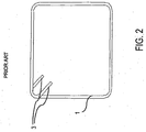
- Fig. 2 shows one lateral reinforcement bar 1 of such a pre-formed mesh seen in a direction of extension of the assembly bars 2 (not shown in this view), after the pre-formed mesh has been bended into the intended final shape with hooks 3 at the ends.
- large diameter longitudinal bars (not shown) are inserted into the corners of the lateral bars 1 such that they extend substantially parallel to the assembly bars 2, for reinforcement in the longitudinal direction.
- the mesh with the longitudinal bars is embedded in concrete, i.e. the mesh is poured over with concrete.
- a resulting structure is shown in Fig. 3 where the mesh of the lateral reinforcement bars 1 and assembly bars 2 together with the longitudinal bars 4 is arranged in a block of concrete 5.
- the lateral reinforcement bars 1 absorb lateral forces and the longitudinal bars 4 absorb longitudinal forces.
- WO 2006/079639 A discloses a structure for strengthening concrete according to the preamble of claim 1.
- the object of the invention is achieved with a structure for strengthening concrete and a method for producing a structure for strengthening concrete according to the independent claims.
- a structure for strengthening concrete comprises at least one bended mesh formed of a pre-formed mesh consisting of lateral bars arranged in parallel and assembly bars arranged in parallel, the assembly bars being arranged perpendicular to the lateral bars and connecting the lateral bars, and an outer cage formed of a pre-formed mesh consisting of lateral bars arranged in parallel and assembly bars arranged in parallel, the assembly bars being arranged perpendicular to the lateral bars and connecting the lateral bars.
- the at least one bended mesh is placed inside the outer cage such that all assembly bars of the at least one bended mesh are enclosed by lateral bars of the outer cage.
- the structure as described above is constituted of at least two members each of which is formed of a pre-formed mesh, and which are inserted into each other.
- forces in the lateral direction of the structure are absorbed from both the lateral reinforcement bars of the at least one bended mesh and the lateral reinforcement bars of the outer cage.
- the structure has excellent reinforcement properties, in particular when being subjected to lateral loads.
- each of the at least one bended mesh and the outer cage can be formed of a pre-formed mesh bended at a plurality of positions (can be formed of a complex member), an extremely complex final structure can be achieved.
- the lateral bars of the at least one bended mesh and the outer cage cross each other seen in the direction of extension of their assembly bars.
- the reinforcement property is further increased, also in the direction of extension of the assembly bars.
- portions of lateral bars of the at least one bended mesh defining a part of its outer circumference and portions of lateral bars of the outer cage defining a part of its outer circumference overlap each other seen in the direction of extension of their assembly bars.
- the portions of lateral bars of the at least one bended mesh and the outer cage are arranged one upon the other when looking at the structure in the direction of extension of the assembly bars.
- the at least one bended mesh when seen in the direction of extension of their assembly bars, has in one direction the same extension as the outer cage and has in a direction perpendicular to the one direction a smaller extension as the outer cage.
- the at least one bended mesh flushes with the outer cage in the one direction so that, on the one hand, the at least one pre-formed mesh cannot be pulled out of the outer cage (i.e. is securely held inside the outer cage), and, on the other hand, the manageability of the whole structure may be improved.
- the lateral bars of the at least one bended mesh do not project from the lateral bars of the outer cage in the lateral direction, thereby improving the usability of the structure.
- At least two bended meshes are inserted into each other such that their lateral bars cross each other seen in the direction of extension of their assembly bars.
- the reinforcement capabilities of the whole structure are further increased, especially in the lateral direction of the structure.
- the at least two bended meshes having their lateral bars crossed with each other with one or more further bended meshes the lateral bars of which do not cross (and preferably also do not overlap) with this at least two bended meshes having their lateral bars crossed with each other.
- the lateral bars of the one or more further bended meshes can also cross with each other.
- a total bending angle through which the lateral bars of the at least one bended mesh are bent is equal to or more than 90°.
- a total bending angle through which the lateral bars of the outer cage are bent is equal to or more than 360°. This ensures a very high lateral reinforcement capability, in particular against lateral loads. Note that the above angles can be selected arbitrary as appropriate, e.g.
- a total bending angle through which the lateral bars of the at least one bended mesh are bent can be equal to or more than 180°, 270°, 360°, 450°, 540°, etc.
- a total bending angle through which the lateral bars of the outer cage are bent can be equal to or more than 450°, 540°, 630 etc.
- the lateral bars can be bent at a plurality of different positions.
- the total bending angle includes bending angles for forming attachment portions at the respective ends of the lateral bars for longitudinal bars to be inserted into the final structure in the longitudinal direction (direction of extension of the assembly bars thereof).
- longitudinal bars cannot only be placed at the above attachment portions but in arbitrary corners (e.g. in all corners) formed by the longitudinal bars of the structure.
- the outer cage is of a rectangular outer shape seen in the direction of extension of its assembly bars, wherein at least one assembly bar is arranged at each side.
- the structure is easy to handle and provides good stability when being arranged in use-position in order to be filled with concrete.
- one or more sides of the outer cage can be free of assembly bars.
- a portion of the outer cage which has been bent after insertion of the at least one bended mesh is provided with at least one assembly bar. This configuration further ensures that the at least one bended mesh is securely held inside the outer cage.
- the method for producing a structure for strengthening concrete according to the invention comprises the steps of
- a structure as described above can be provided, i.e. a structure consisting of at least two members each of which absorbs loads in the lateral direction of the structure.
- the opened outer cage is closed by bending the lateral bars of the opened outer cage along at least one axis substantially parallel to its assembly bars. This way of closing is very easy to achieve and may reduce the manufacturing costs.
- a total bending angle through which the lateral bars are being bent in step d) for closing the outer cage is equal to or more than 90°.
- this angle can be selected arbitrary as appropriate for closing the outer cage, and can be e.g. equal to or more than 180°.
- the lateral bars can be bended at a plurality of different positions.
- a portion of the opened outer cage being bent over in step d) is provided with at least one assembly bar. This ensures that the at least one bended mesh is securely held inside the closed outer cage.
- the at least one bended mesh is inserted into the opened outer cage in a direction substantially parallel to a plane formed by a lateral bar of the outer cage. I.e. the at least one bended mesh is inserted from the side of the opened outer cage.
- the structure is easy to assemble.
- the at least one bended mesh is provided by bending the lateral bars of the pre-formed mesh at a plurality of positions along axis parallel to its assembly bars.
- the at least one outer cage is provided by bending the lateral bars of the pre-formed mesh at a plurality of positions along axis substantially parallel to its assembly bars.
- a total bending angle through which the lateral bars are being bent in step a) is equal to or more than 90°.
- a total bending angle through which the lateral bars are being bent in step b) is equal to or more than 360°. This may lead to a superior reinforcing capability of the resulting structure.
- the total bending angle referred to above is not limited to these angles, and a total bending angle can assume another value, especially a higher value.
- the bending is performed in two different directions, on the one hand, clockwise and, on the other hand, counterclockwise.
- the lateral bars of the pre-formed mesh are being bent from one end side of the lateral bars along plural axis substantially parallel to the assembly bars so as to form a partial cage with a portion of the lateral bars at the other end side projecting outwardly from the partial cage. Due to the formation of a partial cage, the reinforcing capability of the structure is further increased.
- the portion of the lateral bars at the other end side projecting outwardly from the partial cage can itself be a cage structure, i.e. form a partial cage, and can be formed in the same manner as described above.
- a total bending angle through which the lateral bars are being bent to form the partial cage is equal to or more than 90°, preferably equal to or more than 180°, 270° or 360°. With these total bending angles, very good strengthening capabilities may be achieved.
- step d) for closing the outer cage, the portion of the lateral bars at the other end side projecting outwardly from the partial cage is being bent over or the portion of the lateral bars including the partial cage is being bent over.
- the portion of the lateral bars including the partial cage can be bent over such that the partial cage projects into the interior of the at least one bended mesh seen in a direction of extension of their assembly bars (i.e. such that the portion of the lateral bars forming the partial cage and lateral bars of the at least one bended mesh cross each other).
- the at least one bended mesh is inserted in step c) into the partial cage such that their lateral bars cross each other seen in a direction of their assembly bars. This further improves the strengthening capability.
- step a) at least two bended meshes are being provided and are inserted into each other such that their lateral bars cross each other seen in the direction of extension of their assembly bars, and in step c), the at least two bended meshes with their lateral bars crossing each other are being inserted into the opened outer cage.
- the provision of such at least two bended meshes may further enhance the reinforcement capability of the whole structure.
- the structure for strengthening concrete produced according to the method of the invention is the structure as referred to above.
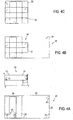
- Fig. 4A shows a bended mesh 10 and an outer cage 20 before assembly.
- the bended mesh 10 as well as the outer cage 20 are formed of a pre-formed mesh as shown in Fig. 1 , i.e. of a pre-formed mesh consisting of a plurality of lateral bars arranged in parallel and a plurality of assembly bars arranged in parallel, wherein the assembly bars are arranged perpendicular to the lateral bars and are connecting the lateral bars.
- the bended mesh 10 is formed by bending lateral bars 12 of the pre-formed mesh (only one lateral bar 12 is shown Figures 4A to 4C ) at seven positions around axes substantially parallel to assembly bars 11 thereof ( Figs. 4A to shows the bended mesh 10 in the direction of extension of the assembly bars 11), 5-times by a bending angle of approximately 90° and 2-times by a bending angle of approximately 45°, wherein the bending is performed clockwise and counter-clockwise.
- Methods and apparatuses for bending pre-formed meshes are known from the prior art, for example from the application WO 2006/079639 A1 of the applicant, the whole content of which is herewith incorporated by reference.
- the longitudinal bars 12 are bended such that the resultant bended mesh 10 has a rectangular outer shape and forms two substantially closed rectangular loops seen in the direction of extension of its assembly bars 11.
- the end bendings 13 of each lateral bar 12 constitute respective attachment portions for longitudinal bars (not shown) to be inserted in the direction of extension of the assembly bars 11 after completion of the structure.
- longitudinal bars cannot be placed only at the above mentioned attachment portions, but in arbitrary corners formed by the lateral bars of the structure.
- all assembly bars 11 (5 in this embodiment) are arranged near one end side in the longitudinal direction of the bended mesh 10. This is important in view of a later insertion of the bended mesh 10 into the outer cage 20.
- the outer cage 20 which is shown in the open state in Fig. 4A is formed of a pre-formed mesh the lateral bars 22 of which having been bent at ten positions along axes substantially parallel to its assembly bars 21, 8-times by a bending angle of approximately 90° and 2-times by a bending angle of approximately 45°.
- the lateral bars 22 have been bent from one end side thereof in order to form a partial cage 24 having a rectangular shape and forming three substantially closed rectangular loops, seen in the direction of extension of the assembly bars 21.
- a portion 25 of the lateral bars 22 at their other end side projects outwardly (sideways) from the partial cage 24, wherein this projecting portion 25 itself is angled by 90°.
- the end bendings 23 of the lateral bars 22 constitute respective attachments portions for longitudinal bars.
- the assembly bars 21 of the partial cage 24 are arranged near one end of the partial cage 24 in its longitudinal direction (in the lower portion of the partial cage 24 in Fig. 4A ) for enabling an insertion of the bended mesh 10 into the middle part of the outer cage 24, as will be described later.
- the assembly bars of a bended mesh (or a plurality of bended meshes) and of an opened outer cage have to be arranged such that there are no assembly bars connected to those portions of the respective lateral bars crossing each other or overlapping each other (seen in the direction of extension of the assembly bars), when inserting the bended mesh into the opened outer cage, i.e. the path of insertion needs to be free of assembly bars.
- the bended mesh 10 is inserted from the opening formed by the projecting portion 25 into the partial cage 24.
- the bended mesh 10 is inserted into the middle portion of the partial cage 24 until a portion of the lateral bars 12 of the bended mesh 10 defining the outer circumference of the bended mesh 10 at one end side in the longitudinal direction of the bended mesh 10 overlaps/flushes with a portion of the lateral bars 22 defining the outer circumference of the partial cage 24 at the width side thereof. It is possible to determine this position by means of the assembly bars 11 preventing a further insertion of the bended mesh 10 when abutting against the lateral bars 22.
- all assembly bars 11, 21 are substantially parallel to each other
- all lateral bars 12, 22 are substantially parallel to each other and arranged alternately on top of each other in the direction of extension of the assembly bars 11, 21.
- the lateral bars 22 constituting the portion 25 are bent at one position around an axis substantially parallel to the assembly bars 21 by a bending angle of 90° for closing the outer cage 20, thereby completing the structure for strengthening concrete.
- the completed structure is shown in Fig. 4C .
- the lateral bars 22 of the outer cage 20 in particular those portions of the lateral bars 22 which define its square outer circumference, enclose all assembly bars 11 of the bended mesh 10.
- each of the four outer sides of the closed outer cage 20 is provided with at least one assembly bar 21.
- one or more sides of the closed outer cage can be free of assembly bars.
- the portions of the lateral bars 12 defining the outer circumference of the bended mesh 10 at the other end side flush and overlap with corresponding portions of the lateral bars 22 defining the outer circumference of the outer cage 20.
- those portions alternately lie on top of each other in the direction of extension of the assembly bars 11, 21.
- the lateral bars 12 of the bended mesh 10 and the lateral bars 22 of the outer cage 20 cross each other at a plurality of positions (nine positions in this embodiment) seen in the direction of extension of their assembly bars 11, 21.
- the completed structure is then provided with longitudinal bars, i.e. longitudinal bars are inserted into the attachment portions 13, 23 and optionally into further corners formed by the lateral bars of the structure, and then the structure is poured over with concrete.
- Figures 5A to 5D show steps of producing a structure for strengthening concrete according to a further embodiment.
- the bended mesh 10 is the same as shown in Figures 4A to 4C .
- the mesh 30 is also formed of a pre-formed mesh as described above. In particular, it is formed by bending lateral bars 32 of the pre-formed mesh at a plurality of positions (eight positions) substantially parallel to the axes of its assembly bars 31 into the shape of a "U", wherein each shank of the "U” is formed of a substantially closed loop seen in the direction of extension of the assembly bars 31.
- all assembly bars 31 of the bended mesh 30 are provided near one longitudinal end of the bended mesh 30 (in the lower portion of the bended mesh 30 in Fig. 5a ).
- the end portions 33 of the lateral bars 32 which are angled by 45°, form respective attachment portions for longitudinal bars.
- the bended mesh 10 and the bended mesh 30 are put into each other, i.e. either the bended mesh 10 is inserted into the bended mesh 30 or vice versa.
- the resultant structure is a complex cage, wherein the longitudinal axes of the bended mesh 10 and of the bended mesh 30 are arranged perpendicular to each other seen in the direction of extension of the assembly bars 11, 31 arranged in parallel.
- the lateral bars 12 and the lateral bars 32 cross each other at twelve positions seen in the direction of extension of the assembly bars 11, 31.
- an opened outer cage 40 is provided.
- the opened outer cage 40 is formed of a pre-formed mesh in the same manner as the outer cage 20.
- lateral bars 42 of the pre-formed mesh are bent at one side (right side in Fig. 5B ) so as to form a partial cage 44 having a rectangular shape and forming of one substantially closed loop, while at the other end side the lateral bars 42 are angled in 90° and project outwardly from the partial cage 44, thereby forming a projecting portion 45.
- the ends of the lateral bars 42 angled in 45° form respective attachment portions 43 for longitudinal bars.
- the complex cage consisting of the bended mesh 10 and the bended mesh 30 is inserted from a side of the opened outer cage (substantially from above in this embodiment) into the opened outer cage 40.
- the complex cage is inserted into a corner of the projecting portion 45 such that all assembly bars 11, 31, 41 are arranged substantially in parallel, as shown in Fig. 5C , and all lateral bars 12, 32, 42 alternately lie on top of each other in the direction of extension of the assembly bars 11, 31, 41.
- the lateral bars 42 including the portion forming the outer cage 44 are bended over at one position by 90° such that the outer cage 44 is partly inserted into the bended mesh 30 (i.e. such that the lateral bars 42 and the lateral bars 32 cross each other seen in the direction of extension of the assembly bars), thereby closing the outer cage 40 and completing the structure for strengthening concrete.
- the completed structure is shown in Fig. 5D .
- the lateral bars 42 of the outer cage 40 (specifically the portions of the lateral bars 42 defining the outer circumference of the outer cage 40) enclose all assembly bars 11, 31 of the bended meshes 10, 30.
- the bended mesh 10 has the same outer extension as the outer cage 40 in the direction of the longitudinal extension of the bended mesh 10
- the bended mesh 30 has the same outer extension as the outer cage 40 in the longitudinal direction of the bended mesh 30 (the bended meshes 10, 30 do not project from the outer circumference of the outer cage 40 defined by its lateral bars 42).
- portions of the lateral bars 12 of the bended mesh 10 defining the outer circumference at the longitudinal ends of the bended mesh 10 and portions of the lateral bars 42 of the outer cage 40 defining the outer circumference of the outer cage 40 overlap with each other (i.e. are arranged on top of each other in the direction of the extension of the assembly bars 11, 41).
- the completed structure is then provided with longitudinal bars, i.e. longitudinal bars are inserted into the attachment portions 13, 33, 43 and optionally into further corners formed by the lateral bars of the structure, and then the structure is poured over with concrete.
- Figures 6 to 8 show further possible shapes of bended meshes, which can also be combined with each other.
- Each of Figures 6 to 8 is a view onto lateral bars of the respective bended mesh in the direction of extension of assembly bars which are not shown.
- Fig. 6 shows a bended mesh where only the lateral bars at the end portions of a pre-formed mesh (having the configuration as described above) have been bent by a bending angle of about 45° in order to form attachment portions for longitudinal bars.
- Fig. 7 shows a bended mesh the lateral bars of which have been bent substantially in the shape of a "U".
- One shank of the "U" is formed of two substantially closed loops and constitutes a first rectangular partial cage, and the other shank is formed of one substantially closed loop and constitutes a second rectangular partial cage.
- the first partial cage comprises six clockwise bends and the second partial cage comprises four counter-clockwise bends.
- Figures 9A to 13A show different structures for strengthening concrete according to the invention which can be produced by the method according to the invention, wherein Figs. 9B to 13A shows the respective bended meshes and outer cages before assembly.
- FIGs. 9A to 13A and 9B to 13B is a view onto lateral bars of the respective structure in the direction of extension of assembly bars.
- Fig. 9A consists of one bended mesh forming three rectangular substantially closed loops and being inserted into an outer cage.
- Fig. 9B the bended mesh is shown before insertion into the outer cage.
- Fig. 10A The structure of Fig. 10A consists of two bended meshes having substantially the shape of the bended mesh 30 and a bended mesh having the shape shown in Fig. 6 .
- the bended mesh having the shape shown in Fig. 6 is inserted into the two bended meshes having substantially the shape of the bended mesh 30.
- All three bended meshes are inserted into an outer cage forming a partial cage at one side (left side in Fig. 10 ).
- Fig. 10B the bended meshes are shown before insertion into the outer cage.
- Fig. 11A The structure of Fig. 11A consists of two adjacent and parallel arranged bended meshes having a rectangular shape and forming one loop (as depicted in Fig. 2 ) and two bended meshes each having the shape of the bended mesh 30 as described above (in Fig. 11B the bended meshes are shown before insertion into the outer cage).
- the two bended meshes having a rectangular shape and forming one loop are inserted into the two bended meshes having the shape of the bended mesh 30 and arranged adjacent and parallel to each other such that they are also arranged adjacent and parallel to each other in the two bended meshes having the shape of the bended mesh 30.
- Fig. 11A consists of two adjacent and parallel arranged bended meshes having a rectangular shape and forming one loop (as depicted in Fig. 2 ) and two bended meshes each having the shape of the bended mesh 30 as described above (in Fig. 11
- the lateral bars of the two bended meshes having a rectangular shape and forming one loop do neither cross nor overlap with each other seen in the direction of their assembly bars, and also the lateral bars of the two bended meshes having the shape of the bended mesh 30 do neither cross nor overlap with each other seen in the direction of their assembly bars.
- the lateral bars of each of the two bended meshes having a rectangular shape and forming one loop crosses the lateral bars of both bended meshes having the shape of the bended mesh 30.
- longitudinal axes of the two bended meshes each having the shape of the bended mesh 30 are perpendicular to longitudinal axes of the two adjacent and parallel arranged bended meshes. All bended meshes are inserted into an outer cage forming a single loop, as shown in Fig. 11A .
- Fig. 12A shows a construction consisting of a rectangular outer cage with a partial cage and two bended meshes (bended like the mesh 30) which are placed inside the outer cage.
- the two bended meshes are arranged parallel and adjacent to each other, but do not overlap/cross each other.
- Fig. 12B shows the bended meshes before insertion into the outer cage.
- Fig. 13A shows a similar construction to Fig. 11B , with the two bended meshes having the shape of the bended mesh 10 instead of the bended mesh 30.
- Fig. 13B shows the bended meshes before insertion into the outer cage.
- Figures 14A to 14C show different shapes that are considered to be a "partial cage” according to the invention.
- the shape of Fig. 14A is achieved by bending lateral bars of a pre-formed mesh at six positions with a total bending angle of substantially 495° (5x90° + 1x45°) thereby forming two substantially closed loops (seen in the direction of extension of corresponding assembly bars not shown).
- the shape of Fig. 14B is achieved by bending lateral bars at four positions with a total bending angle of 315° (3x90° + 1x45°), thereby forming a substantially closed loop.
- the shape of Fig. 14C is achieved by bending lateral bars at a first position by 90° and at a second position by 45°.
- the above described structures are merely examples for a partial cage and do not limit the term partial cage in any aspect.
Landscapes
- Engineering & Computer Science (AREA)
- Architecture (AREA)
- Civil Engineering (AREA)
- Structural Engineering (AREA)
- Reinforcement Elements For Buildings (AREA)
- Manufacturing Of Tubular Articles Or Embedded Moulded Articles (AREA)
Claims (14)
- Structure permettant de renforcer le béton comprenant
au moins une maille pliée (10 ; 30) formée d'une maille préformée constituée de barres latérales (12 ; 32) agencées en parallèle et de barres d'assemblage (11 ; 31) agencées en parallèle, les barres d'assemblage étant agencées de manière perpendiculaire aux barres latérales et raccordant les barres latérales, et
une cage externe (20 ; 40) formée d'une maille préformée constituée de barres latérales (22 ; 42) agencées en parallèle et de barres d'assemblage (21 ; 41) agencées en parallèle, les barres d'assemblage étant agencées de manière perpendiculaire aux barres latérales et raccordant les barres latérales,
dans laquelle des barres latérales de l'au moins une maille pliée et de la cage externe se croisent les unes avec les autres vues dans la direction d'extension de leurs barres d'assemblage,
caractérisée en ce que
l'au moins une maille pliée (10 ; 30) est placée à l'intérieur de la cage externe (20 ; 40) de sorte que toutes les barres d'assemblage (11 ; 31) de l'au moins une maille pliée soient entourées par des barres latérales (22 ; 42) de la cage externe. - Structure selon la revendication 1, dans laquelle des parties de barres latérales de l'au moins une maille pliée définissant une partie de sa circonférence externe et des parties de barres latérales de la cage externe définissant une partie de sa circonférence externe se chevauchent les unes les autres vues dans la direction d'extension de leurs barres d'assemblage.
- Structure selon la revendication 1 ou 2, dans laquelle l'au moins une maille pliée, vue dans la direction d'extension de ses barres d'assemblage, a dans une direction la même extension que la cage externe et a dans une direction perpendiculaire à la première direction une extension plus petite que la cage externe.
- Structure selon l'une quelconque des revendications 1 à 3, comprenant au moins deux mailles pliées insérées l'une dans l'autre de sorte que leurs barres latérales se croisent les unes avec les autres vues dans la direction d'extension de leurs barres d'assemblage, et/ou au moins deux mailles pliées agencées de sorte que leurs barres latérales ne se croisent pas les unes avec les autres, et de préférence ne se chevauchent pas les unes avec les autres, vues dans la direction d'extension de leurs barres d'assemblage.
- Structure selon l'une quelconque des revendications 1 à 4, dans laquelle
un angle de pliage total par lequel les barres latérales de l'au moins une maille pliée sont pliées est supérieur ou égal à 90°, et/ou
un angle de pliage total par lequel les barres latérales de la cage externe sont pliées est supérieur ou égal à 360°. - Structure selon l'une quelconque des revendications 1 à 5, dans laquelle la cage externe est d'une forme externe rectangulaire vue dans la direction d'extension de ses barres d'assemblage, dans laquelle au moins une barre de montage est agencée au niveau de chaque côté ou au moins un côté est sans barres d'assemblage.
- Procédé permettant de produire une structure pour renforcer le béton, comprenant les étapes consistanta) à fournir au moins une maille pliée (10 ; 30) formée d'une maille préformée constituée de barres latérales (12 ; 32) agencées en parallèle et de barres d'assemblage (11 ; 31) agencées en parallèle, les barres d'assemblage étant agencées de manière perpendiculaire aux barres latérales et raccordant les barres latérales,b) à fournir une cage externe ouverte (20 ; 40) formée d'une maille préformée constituée de barres latérales (22 ; 42) agencées en parallèle et de barres d'assemblage (21 ; 41) agencées en parallèle, les barres d'assemblage étant agencées de manière perpendiculaire aux barres latérales et raccordant les barres latérales,c) à insérer l'au moins une maille pliée (10 ; 30) dans la cage externe ouverte (20 ; 40), etd) à fermer la cage externe (20 ; 40) de sorte que toutes les barres d'assemblage (11 ; 31) de l'au moins une maille pliée soient entourées par des barres latérales (22 ; 42) de la cage externe.
- Procédé selon la revendication 7, dans lequel, dans l'étape d) la cage externe ouverte est fermée par pliage des barres latérales de la cage externe ouverte le long d'au moins un axe substantiellement parallèle à ses barres d'assemblage.
- Procédé selon la revendication 8, dans lequel un angle de pliage total par lequel les barres latérales étant pliées dans l'étape d) pour fermer la cage externe est supérieur ou égal à 90°.
- Procédé selon l'une quelconque des revendications 7 à 9, dans lequel, dans l'étape c) l'au moins une maille pliée est insérée dans la cage externe ouverte dans une direction substantiellement parallèle à un plan formé par une barre latérale de la cage externe.
- Procédé selon l'une quelconque des revendications 7 à 10, dans lequel
dans l'étape a) l'au moins une maille pliée est fournie par pliage des barres latérales de la maille préformée au niveau d'une pluralité de positions le long d'axes substantiellement parallèles à ses barres d'assemblage, et/ou
dans l'étape b) la cage externe est fournie par pliage des barres latérales de la maille préformée au niveau d'une pluralité de positions le long d'axes substantiellement parallèles à ses barres d'assemblage. - Procédé selon la revendication 11, dans lequel
un angle de pliage total par lequel les barres latérales sont pliées dans l'étape a) est supérieur ou égal à 90°, et/ou
un angle de pliage total par lequel les barres latérales sont pliées dans l'étape b) est supérieur ou égal à 360°. - Procédé selon l'une quelconque des revendications 7 à 12, dans lequel
dans l'étape a) au moins deux mailles pliées sont fournies et sont insérées l'une dans l'autre de sorte que leurs barres latérales se croisent les unes avec les autres vues dans la direction d'extension de leurs barres d'assemblage, et
dans l'étape c) l'au moins deux mailles pliées avec leurs barres latérales se croisant les unes avec les autres sont insérées dans la cage externe ouverte. - Procédé selon l'une quelconque des revendications 7 à 13, dans lequel la structure produite permettant de renforcer le béton est la structure selon l'une quelconque des revendications 1 à 6.
Applications Claiming Priority (1)
| Application Number | Priority Date | Filing Date | Title |
|---|---|---|---|
| PCT/EP2010/059406 WO2012000559A1 (fr) | 2010-07-01 | 2010-07-01 | Structure pour renforcer le béton et procédé de production d'une structure permettant de renforcer le béton |
Publications (2)
| Publication Number | Publication Date |
|---|---|
| EP2588677A1 EP2588677A1 (fr) | 2013-05-08 |
| EP2588677B1 true EP2588677B1 (fr) | 2016-03-16 |
Family
ID=43768736
Family Applications (1)
| Application Number | Title | Priority Date | Filing Date |
|---|---|---|---|
| EP10736996.9A Active EP2588677B1 (fr) | 2010-07-01 | 2010-07-01 | Structure pour renforcer le béton et procédé de production d'une structure permettant de renforcer le béton |
Country Status (5)
| Country | Link |
|---|---|
| EP (1) | EP2588677B1 (fr) |
| CY (1) | CY1117733T1 (fr) |
| ES (1) | ES2576790T3 (fr) |
| PL (1) | PL2588677T3 (fr) |
| WO (1) | WO2012000559A1 (fr) |
Citations (1)
| Publication number | Priority date | Publication date | Assignee | Title |
|---|---|---|---|---|
| WO1998029618A1 (fr) * | 1997-01-03 | 1998-07-09 | Apostolos Konstantinidis | Etriers en spirale antisismiques destines au renforcement d'elements structuraux porteurs |
Family Cites Families (7)
| Publication number | Priority date | Publication date | Assignee | Title |
|---|---|---|---|---|
| US3744207A (en) * | 1971-05-10 | 1973-07-10 | G Oroschakoff | Reinforcement for reinforced concrete structures |
| FR2267432A1 (en) * | 1974-04-11 | 1975-11-07 | Longometal Sa | Wire mesh cages for concrete reinforcement - are formed from mesh sheets folded into tubular form |
| AT378979B (de) * | 1983-09-01 | 1985-10-25 | Best Baueisen & Stahl | Bewehrung fuer stahlbetonkonstruktionen |
| DE3943654C2 (de) * | 1989-04-22 | 1997-03-20 | Hinrich Podendorf | Bewehrungskorb aus Betonstabstahl |
| US5487251A (en) * | 1994-05-06 | 1996-01-30 | Independent Concrete Pipe | Apparatus and method for reinforcing cast structures |
| US6247501B1 (en) * | 2000-09-29 | 2001-06-19 | John L. Kaines | Clip-on stirrup mat |
| PL1848867T3 (pl) * | 2005-01-25 | 2017-09-29 | Sidenor Sa | Struktura wzmacniająca |
-
2010
- 2010-07-01 EP EP10736996.9A patent/EP2588677B1/fr active Active
- 2010-07-01 WO PCT/EP2010/059406 patent/WO2012000559A1/fr not_active Ceased
- 2010-07-01 ES ES10736996.9T patent/ES2576790T3/es active Active
- 2010-07-01 PL PL10736996.9T patent/PL2588677T3/pl unknown
-
2016
- 2016-06-15 CY CY20161100531T patent/CY1117733T1/el unknown
Patent Citations (1)
| Publication number | Priority date | Publication date | Assignee | Title |
|---|---|---|---|---|
| WO1998029618A1 (fr) * | 1997-01-03 | 1998-07-09 | Apostolos Konstantinidis | Etriers en spirale antisismiques destines au renforcement d'elements structuraux porteurs |
Also Published As
| Publication number | Publication date |
|---|---|
| WO2012000559A1 (fr) | 2012-01-05 |
| EP2588677A1 (fr) | 2013-05-08 |
| PL2588677T3 (pl) | 2016-09-30 |
| CY1117733T1 (el) | 2017-05-17 |
| ES2576790T3 (es) | 2016-07-11 |
Similar Documents
| Publication | Publication Date | Title |
|---|---|---|
| CN107849845B (zh) | 网格结构及其生产装置和方法 | |
| JP4712021B2 (ja) | 鉄筋コンクリート構造物中の配筋に用いる補強鉄筋及び配筋構造 | |
| JP6905710B2 (ja) | 鉄筋籠および鉄筋籠の形状回復方法 | |
| JP2022036882A (ja) | 柱中柱組付型拘束の接合構造 | |
| KR100629155B1 (ko) | 사각형 돌망태 | |
| CN201232294Y (zh) | 高强度抗震钢筋笼 | |
| EP2588677B1 (fr) | Structure pour renforcer le béton et procédé de production d'une structure permettant de renforcer le béton | |
| EP2780517B1 (fr) | Structure de renfort en acier pour béton | |
| CN104164927A (zh) | 钢筋混凝土墙版的钢筋结构及其工法 | |
| JP6781747B2 (ja) | 二重巻補強方法及び二重巻補強方法で製造された製品 | |
| KR101164621B1 (ko) | 테트라포드 결속 시스템 | |
| TWM597797U (zh) | 建築物柱體之鋼筋耐震結構 | |
| JP3225556U (ja) | 耐震帯筋 | |
| CN209443667U (zh) | 用于柱体结构的复合式围束箍筋 | |
| KR20110000311A (ko) | 개비온 블록의 단위면부재 및 이를 이용한 개비온 블록 및 매트리스 개비온의 제조방법 | |
| JP4328230B2 (ja) | 組積造の耐震性向上施工法 | |
| CN104372855B (zh) | 一种多构件钢筋混凝土节点及其构建方法 | |
| TWM621077U (zh) | 耐震結構柱及其雙核心鋼筋結構 | |
| CN201288396Y (zh) | 复螺旋箍筋结合钢筋网结构 | |
| JP2002266470A (ja) | 開口部を有する鉄筋または鉄骨鉄筋コンクリート造梁、その開口部の補強方法および補強筋 | |
| RU77298U1 (ru) | Свая железобетонная с ненапрягаемой арматурой | |
| CN221441909U (zh) | 用于梁钢筋系统的箍筋模组 | |
| CN210342435U (zh) | 钢筋混凝土梁加固结构 | |
| JP7232854B2 (ja) | 別異平面上に形成された端部フックを有する補強筋を用いた補強筋二重巻き配筋工法並びに、この配筋工法で構成される構造物、及びこの配筋工法に適用される補強筋 | |
| CN204266372U (zh) | 一种多构件钢筋混凝土节点 |
Legal Events
| Date | Code | Title | Description |
|---|---|---|---|
| PUAI | Public reference made under article 153(3) epc to a published international application that has entered the european phase |
Free format text: ORIGINAL CODE: 0009012 |
|
| 17P | Request for examination filed |
Effective date: 20130129 |
|
| AK | Designated contracting states |
Kind code of ref document: A1 Designated state(s): AL AT BE BG CH CY CZ DE DK EE ES FI FR GB GR HR HU IE IS IT LI LT LU LV MC MK MT NL NO PL PT RO SE SI SK SM TR |
|
| DAX | Request for extension of the european patent (deleted) | ||
| 17Q | First examination report despatched |
Effective date: 20141104 |
|
| GRAP | Despatch of communication of intention to grant a patent |
Free format text: ORIGINAL CODE: EPIDOSNIGR1 |
|
| INTG | Intention to grant announced |
Effective date: 20150317 |
|
| GRAS | Grant fee paid |
Free format text: ORIGINAL CODE: EPIDOSNIGR3 |
|
| GRAA | (expected) grant |
Free format text: ORIGINAL CODE: 0009210 |
|
| AK | Designated contracting states |
Kind code of ref document: B1 Designated state(s): AL AT BE BG CH CY CZ DE DK EE ES FI FR GB GR HR HU IE IS IT LI LT LU LV MC MK MT NL NO PL PT RO SE SI SK SM TR |
|
| REG | Reference to a national code |
Ref country code: GB Ref legal event code: FG4D |
|
| REG | Reference to a national code |
Ref country code: CH Ref legal event code: EP |
|
| REG | Reference to a national code |
Ref country code: IE Ref legal event code: FG4D |
|
| REG | Reference to a national code |
Ref country code: AT Ref legal event code: REF Ref document number: 781412 Country of ref document: AT Kind code of ref document: T Effective date: 20160415 |
|
| REG | Reference to a national code |
Ref country code: DE Ref legal event code: R096 Ref document number: 602010031212 Country of ref document: DE |
|
| REG | Reference to a national code |
Ref country code: CH Ref legal event code: NV Representative=s name: NOVAGRAAF INTERNATIONAL SA, CH Ref country code: RO Ref legal event code: EPE |
|
| REG | Reference to a national code |
Ref country code: NL Ref legal event code: FP |
|
| REG | Reference to a national code |
Ref country code: ES Ref legal event code: FG2A Ref document number: 2576790 Country of ref document: ES Kind code of ref document: T3 Effective date: 20160711 |
|
| REG | Reference to a national code |
Ref country code: LT Ref legal event code: MG4D |
|
| PG25 | Lapsed in a contracting state [announced via postgrant information from national office to epo] |
Ref country code: HR Free format text: LAPSE BECAUSE OF FAILURE TO SUBMIT A TRANSLATION OF THE DESCRIPTION OR TO PAY THE FEE WITHIN THE PRESCRIBED TIME-LIMIT Effective date: 20160316 Ref country code: FI Free format text: LAPSE BECAUSE OF FAILURE TO SUBMIT A TRANSLATION OF THE DESCRIPTION OR TO PAY THE FEE WITHIN THE PRESCRIBED TIME-LIMIT Effective date: 20160316 Ref country code: NO Free format text: LAPSE BECAUSE OF FAILURE TO SUBMIT A TRANSLATION OF THE DESCRIPTION OR TO PAY THE FEE WITHIN THE PRESCRIBED TIME-LIMIT Effective date: 20160616 |
|
| PG25 | Lapsed in a contracting state [announced via postgrant information from national office to epo] |
Ref country code: LV Free format text: LAPSE BECAUSE OF FAILURE TO SUBMIT A TRANSLATION OF THE DESCRIPTION OR TO PAY THE FEE WITHIN THE PRESCRIBED TIME-LIMIT Effective date: 20160316 Ref country code: LT Free format text: LAPSE BECAUSE OF FAILURE TO SUBMIT A TRANSLATION OF THE DESCRIPTION OR TO PAY THE FEE WITHIN THE PRESCRIBED TIME-LIMIT Effective date: 20160316 Ref country code: SE Free format text: LAPSE BECAUSE OF FAILURE TO SUBMIT A TRANSLATION OF THE DESCRIPTION OR TO PAY THE FEE WITHIN THE PRESCRIBED TIME-LIMIT Effective date: 20160316 |
|
| REG | Reference to a national code |
Ref country code: GR Ref legal event code: EP Ref document number: 20160401259 Country of ref document: GR Effective date: 20160729 |
|
| PG25 | Lapsed in a contracting state [announced via postgrant information from national office to epo] |
Ref country code: IS Free format text: LAPSE BECAUSE OF FAILURE TO SUBMIT A TRANSLATION OF THE DESCRIPTION OR TO PAY THE FEE WITHIN THE PRESCRIBED TIME-LIMIT Effective date: 20160716 Ref country code: EE Free format text: LAPSE BECAUSE OF FAILURE TO SUBMIT A TRANSLATION OF THE DESCRIPTION OR TO PAY THE FEE WITHIN THE PRESCRIBED TIME-LIMIT Effective date: 20160316 |
|
| PG25 | Lapsed in a contracting state [announced via postgrant information from national office to epo] |
Ref country code: SK Free format text: LAPSE BECAUSE OF FAILURE TO SUBMIT A TRANSLATION OF THE DESCRIPTION OR TO PAY THE FEE WITHIN THE PRESCRIBED TIME-LIMIT Effective date: 20160316 Ref country code: PT Free format text: LAPSE BECAUSE OF FAILURE TO SUBMIT A TRANSLATION OF THE DESCRIPTION OR TO PAY THE FEE WITHIN THE PRESCRIBED TIME-LIMIT Effective date: 20160718 Ref country code: CZ Free format text: LAPSE BECAUSE OF FAILURE TO SUBMIT A TRANSLATION OF THE DESCRIPTION OR TO PAY THE FEE WITHIN THE PRESCRIBED TIME-LIMIT Effective date: 20160316 Ref country code: SM Free format text: LAPSE BECAUSE OF FAILURE TO SUBMIT A TRANSLATION OF THE DESCRIPTION OR TO PAY THE FEE WITHIN THE PRESCRIBED TIME-LIMIT Effective date: 20160316 |
|
| REG | Reference to a national code |
Ref country code: DE Ref legal event code: R097 Ref document number: 602010031212 Country of ref document: DE |
|
| PG25 | Lapsed in a contracting state [announced via postgrant information from national office to epo] |
Ref country code: BE Free format text: LAPSE BECAUSE OF FAILURE TO SUBMIT A TRANSLATION OF THE DESCRIPTION OR TO PAY THE FEE WITHIN THE PRESCRIBED TIME-LIMIT Effective date: 20160316 |
|
| PLBE | No opposition filed within time limit |
Free format text: ORIGINAL CODE: 0009261 |
|
| STAA | Information on the status of an ep patent application or granted ep patent |
Free format text: STATUS: NO OPPOSITION FILED WITHIN TIME LIMIT |
|
| PG25 | Lapsed in a contracting state [announced via postgrant information from national office to epo] |
Ref country code: DK Free format text: LAPSE BECAUSE OF FAILURE TO SUBMIT A TRANSLATION OF THE DESCRIPTION OR TO PAY THE FEE WITHIN THE PRESCRIBED TIME-LIMIT Effective date: 20160316 |
|
| 26N | No opposition filed |
Effective date: 20161219 |
|
| PG25 | Lapsed in a contracting state [announced via postgrant information from national office to epo] |
Ref country code: MC Free format text: LAPSE BECAUSE OF FAILURE TO SUBMIT A TRANSLATION OF THE DESCRIPTION OR TO PAY THE FEE WITHIN THE PRESCRIBED TIME-LIMIT Effective date: 20160316 |
|
| PG25 | Lapsed in a contracting state [announced via postgrant information from national office to epo] |
Ref country code: FR Free format text: LAPSE BECAUSE OF NON-PAYMENT OF DUE FEES Effective date: 20160801 |
|
| REG | Reference to a national code |
Ref country code: FR Ref legal event code: ST Effective date: 20170331 |
|
| REG | Reference to a national code |
Ref country code: IE Ref legal event code: MM4A |
|
| PG25 | Lapsed in a contracting state [announced via postgrant information from national office to epo] |
Ref country code: SI Free format text: LAPSE BECAUSE OF FAILURE TO SUBMIT A TRANSLATION OF THE DESCRIPTION OR TO PAY THE FEE WITHIN THE PRESCRIBED TIME-LIMIT Effective date: 20160316 |
|
| PG25 | Lapsed in a contracting state [announced via postgrant information from national office to epo] |
Ref country code: IE Free format text: LAPSE BECAUSE OF NON-PAYMENT OF DUE FEES Effective date: 20160701 |
|
| PG25 | Lapsed in a contracting state [announced via postgrant information from national office to epo] |
Ref country code: LU Free format text: LAPSE BECAUSE OF NON-PAYMENT OF DUE FEES Effective date: 20160701 |
|
| PG25 | Lapsed in a contracting state [announced via postgrant information from national office to epo] |
Ref country code: HU Free format text: LAPSE BECAUSE OF FAILURE TO SUBMIT A TRANSLATION OF THE DESCRIPTION OR TO PAY THE FEE WITHIN THE PRESCRIBED TIME-LIMIT; INVALID AB INITIO Effective date: 20100701 |
|
| PG25 | Lapsed in a contracting state [announced via postgrant information from national office to epo] |
Ref country code: MT Free format text: LAPSE BECAUSE OF NON-PAYMENT OF DUE FEES Effective date: 20160731 |
|
| REG | Reference to a national code |
Ref country code: AT Ref legal event code: UEP Ref document number: 781412 Country of ref document: AT Kind code of ref document: T Effective date: 20160316 |
|
| PGFP | Annual fee paid to national office [announced via postgrant information from national office to epo] |
Ref country code: PL Payment date: 20250620 Year of fee payment: 16 |
|
| PGFP | Annual fee paid to national office [announced via postgrant information from national office to epo] |
Ref country code: RO Payment date: 20250626 Year of fee payment: 16 |
|
| PGFP | Annual fee paid to national office [announced via postgrant information from national office to epo] |
Ref country code: TR Payment date: 20250626 Year of fee payment: 16 |
|
| PGFP | Annual fee paid to national office [announced via postgrant information from national office to epo] |
Ref country code: NL Payment date: 20250723 Year of fee payment: 16 |
|
| PGFP | Annual fee paid to national office [announced via postgrant information from national office to epo] |
Ref country code: ES Payment date: 20250819 Year of fee payment: 16 |
|
| PGFP | Annual fee paid to national office [announced via postgrant information from national office to epo] |
Ref country code: DE Payment date: 20250728 Year of fee payment: 16 |
|
| PGFP | Annual fee paid to national office [announced via postgrant information from national office to epo] |
Ref country code: GR Payment date: 20250721 Year of fee payment: 16 |
|
| PGFP | Annual fee paid to national office [announced via postgrant information from national office to epo] |
Ref country code: IT Payment date: 20250731 Year of fee payment: 16 |
|
| PGFP | Annual fee paid to national office [announced via postgrant information from national office to epo] |
Ref country code: BG Payment date: 20250718 Year of fee payment: 16 Ref country code: GB Payment date: 20250724 Year of fee payment: 16 |
|
| PGFP | Annual fee paid to national office [announced via postgrant information from national office to epo] |
Ref country code: AL Payment date: 20250718 Year of fee payment: 16 Ref country code: AT Payment date: 20250721 Year of fee payment: 16 |
|
| PGFP | Annual fee paid to national office [announced via postgrant information from national office to epo] |
Ref country code: CH Payment date: 20250801 Year of fee payment: 16 |
|
| PGFP | Annual fee paid to national office [announced via postgrant information from national office to epo] |
Ref country code: MK Payment date: 20250618 Year of fee payment: 16 |
|
| PGFP | Annual fee paid to national office [announced via postgrant information from national office to epo] |
Ref country code: CY Payment date: 20250612 Year of fee payment: 16 |