EP2589395A1 - Système de clamp et de poche de sang - Google Patents
Système de clamp et de poche de sang Download PDFInfo
- Publication number
- EP2589395A1 EP2589395A1 EP11800536.2A EP11800536A EP2589395A1 EP 2589395 A1 EP2589395 A1 EP 2589395A1 EP 11800536 A EP11800536 A EP 11800536A EP 2589395 A1 EP2589395 A1 EP 2589395A1
- Authority
- EP
- European Patent Office
- Prior art keywords
- section
- engagement
- clamp
- tube
- bag
- Prior art date
- Legal status (The legal status is an assumption and is not a legal conclusion. Google has not performed a legal analysis and makes no representation as to the accuracy of the status listed.)
- Granted
Links
Images


Classifications
-
- A—HUMAN NECESSITIES
- A61—MEDICAL OR VETERINARY SCIENCE; HYGIENE
- A61J—CONTAINERS SPECIALLY ADAPTED FOR MEDICAL OR PHARMACEUTICAL PURPOSES; DEVICES OR METHODS SPECIALLY ADAPTED FOR BRINGING PHARMACEUTICAL PRODUCTS INTO PARTICULAR PHYSICAL OR ADMINISTERING FORMS; DEVICES FOR ADMINISTERING FOOD OR MEDICINES ORALLY; BABY COMFORTERS; DEVICES FOR RECEIVING SPITTLE
- A61J1/00—Containers specially adapted for medical or pharmaceutical purposes
- A61J1/14—Details; Accessories therefor
- A61J1/20—Arrangements for transferring or mixing fluids, e.g. from vial to syringe
- A61J1/2089—Containers or vials which are to be joined to each other in order to mix their contents
-
- A—HUMAN NECESSITIES
- A61—MEDICAL OR VETERINARY SCIENCE; HYGIENE
- A61M—DEVICES FOR INTRODUCING MEDIA INTO, OR ONTO, THE BODY; DEVICES FOR TRANSDUCING BODY MEDIA OR FOR TAKING MEDIA FROM THE BODY; DEVICES FOR PRODUCING OR ENDING SLEEP OR STUPOR
- A61M1/00—Suction or pumping devices for medical purposes; Devices for carrying-off, for treatment of, or for carrying-over, body-liquids; Drainage systems
- A61M1/02—Blood transfusion apparatus
- A61M1/0209—Multiple bag systems for separating or storing blood components
- A61M1/0218—Multiple bag systems for separating or storing blood components with filters
-
- A—HUMAN NECESSITIES
- A61—MEDICAL OR VETERINARY SCIENCE; HYGIENE
- A61M—DEVICES FOR INTRODUCING MEDIA INTO, OR ONTO, THE BODY; DEVICES FOR TRANSDUCING BODY MEDIA OR FOR TAKING MEDIA FROM THE BODY; DEVICES FOR PRODUCING OR ENDING SLEEP OR STUPOR
- A61M39/00—Tubes, tube connectors, tube couplings, valves, access sites or the like, specially adapted for medical use
- A61M39/22—Valves or arrangement of valves
- A61M39/28—Clamping means for squeezing flexible tubes, e.g. roller clamps
- A61M39/284—Lever clamps
-
- A—HUMAN NECESSITIES
- A61—MEDICAL OR VETERINARY SCIENCE; HYGIENE
- A61M—DEVICES FOR INTRODUCING MEDIA INTO, OR ONTO, THE BODY; DEVICES FOR TRANSDUCING BODY MEDIA OR FOR TAKING MEDIA FROM THE BODY; DEVICES FOR PRODUCING OR ENDING SLEEP OR STUPOR
- A61M1/00—Suction or pumping devices for medical purposes; Devices for carrying-off, for treatment of, or for carrying-over, body-liquids; Drainage systems
- A61M1/02—Blood transfusion apparatus
- A61M1/0209—Multiple bag systems for separating or storing blood components
Definitions
- the present invention relates to a clamp which closes and opens a flow path in a tube and to a blood bag system having the clamp.
- the blood (whole blood) obtained by blood donation or a blood component prepared from the whole blood is separated by centrifugation into a plurality of layers.
- the whole blood is separated into a light supernatant PPP (platelet poor plasma) fraction, a heavy precipitated CRC (concentrated red blood cells) fraction, and a buffy coat formed therebetween.
- the buffy coat is centrifuged, it is separated into a supernatant component that contains platelets and leukocytes, and a precipitated component that contains red blood cells.
- the residual component left after removal of leukocytes and platelets from whole blood is centrifuged, it is separated into a plasma layer as the supernatant component and a red blood cell layer as the precipitated component.
- a blood bag system For separating whole blood into a plurality of blood components and containing and preserving the blood components in a plurality of preservation bags, or for further separating a blood component prepared from whole blood into a plurality of blood components and containing and preserving the blood components in a plurality of preservation bags, a blood bag system has hitherto been used in which a plurality of bags are interconnected by a plurality of tubes (refer to, for example, US Patent No. 6910998 ). Besides, in such a blood bag system, for conducting predetermined blood treatments by switching over the communication states between the bags, clamps are provided for closing and opening the flow paths in the tubes (refer to, for example, Japanese Patent Publication No. Hei 5-23792 ).
- Such conventional clamps are each composed of a member which is formed in a flat C shape as a whole.
- the clamp includes a pair of pressing sections for pressing side surfaces of a tube, and an engagement section by which end portions of the C shape can be engaged with each other and the engagement can be released. When the end portions are engaged with each other and the tube is pressed by the pair of pressing sections, the flow path in the tube is closed.
- the flow path in the tube is opened at the time when the component obtained by centrifugation of the blood component is transferred from a bag into another bag; in this case, the flow path in the tube must be securely closed at other times than the time of transfer.
- the conventional clamp has only one engagement section and, moreover, the engagement section can be easily operated by a finger of the person who handles the clamp. Therefore, even a light touch of a finger on the clamp may open the tube, which may influence the smoothness in carrying out the blood treatment.
- the present invention has been made in consideration of the above-mentioned problem, Accordingly, it is an object of the present invention to provide a clamp which can be opened and closed and by which a closed state of a tube can be maintained assuredly and stably, and a blood bag system.
- a clamp for closing and opening a flow path in a tube including: a protrusion section which presses the tube; a locking section having a first engagement section and a second engagement section which form therebetween an engagement groove capable of engagement with the protrusion section; a first engagement release section which releases an engaged state between the first engagement section and the protrusion section; and a second engagement release section which releases an engaged state between the second engagement section and the protrusion section, wherein the flow path in the tube is opened when the engaged states between the protrusion section and the first engagement section and the second engagement section are released.
- the lock of the protrusion section by the locking section is not released unless both the engagement of the first engagement release section and the engagement of the second engagement release section are released. Therefore, a closed state of the tube can be maintained reliably and stably.
- the above-mentioned clamp preferably has a configuration wherein: the clamp includes, integrally formed, a base section with the locking section erected, an opening/closing section with the protrusion section erected, and a bent section interconnecting the base section and the opening/closing section so that the base section and the opening/closing section are opposed to each other; the first engagement section and the second engagement section are disposed in this order along the direction from a tip of the base section toward the bent section side; and the second engagement release section is located between the protrusion section and the bent section in a condition where the protrusion section and the locking section are engaged with each other.
- the second engagement release section is located in such a position as to be difficult to operate by a finger of the person who handles the clamp. Therefore, the closed state of the tube can be maintained further assuredly.
- the second engagement release section projects from the second engagement section toward the bent section side, and a hook piece with which a release pin for putting the second engagement release section into a releasing state can be engaged is provided at a tip of the second engagement release section.
- the first engagement release section projects from the first engagement section in a direction for spacing away from the second engagement section, and is located between the base section and the opening/closing section in a condition where the protrusion section and the locking section are engaged with each other.
- the first engagement release section is located in such a position as to be hard to operate by a finger of the person who handles the clamp. This ensures that the closed state of the tube can be maintained further reliably.
- the opening/closing section is provided with an opening section which partly exposes the first engagement release section so that the first engagement release section can be pressed from outside of the opening/closing section.
- the first engagement release section can be pressed from outside of the opening/closing section, through the opening section. Therefore, even in the case where means for operating the first engagement release section is provided at a position outside of the first engagement release section, the first engagement release section can be easily put into a releasing state.
- a blood bag system including: a plurality of bags each configured to contain whole blood or a blood component; at least one tube which interconnects the plurality of bags; and the above-mentioned clamp attached to the tube.
- a blood bag system including: a first bag configured to contain a blood component; a second bag configured to contain a supernatant component obtained by centrifugation of the blood component; a third bag configured to contain a preservation liquid for preservation of a precipitated component obtained by centrifugation of the blood component; a transfer line which has a branching section at an intermediate position, interconnects the first bag and the second bag, and interconnects the first bag and the third bag; and the above-mentioned clamp attached to a tube between the first bag and the branching section of the transfer line.
- the clamp which can stably maintains the locking state and can be opened when necessary is attached to the tube. Therefore, it is possible, by opening and closing the flow path in the tube interconnecting the bags, to switch over the communication states between the bags and to suitably perform desired blood treatments.
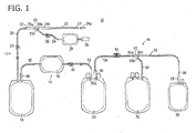
- FIG. 1 is a plan view of a blood bag system 10 according to one embodiment of the present invention.
- the blood bag system 10 is for centrifuging blood containing a plurality of components into a plurality of components differing in specific gravity (for example, three components including a low specific gravity component, an intermediate specific gravity component and a high specific gravity component, or two components including a low specific gravity component and a high specific gravity component) and containing and preserving the components separately in different bags.
- the blood bag system 10 according to this embodiment is configured to centrifuge a residual blood component, obtained by removing leukocytes and platelets from whole blood, into two components including plasma and concentrated red blood cells, and to contain and preserve the plasma and the concentrated red blood cells separately in different bags.
- the blood bag system 10 includes a blood collection section 12 for collection of blood (whole blood) from a donor, a pretreatment section 14 for removing a predetermined blood component from the whole blood, and a separating treatment section 16 by which the residual blood component obtained upon removal of the predetermined component is centrifuged into a plurality of blood components and the blood components are contained (reserved) in different bags,
- the blood collection section 12 includes a blood collection bag 18, first and second blood collection tubes 20 and 22, a blood collection needle 24, a branching connector 26, and a first flow blood bag 28.
- the blood collection bag 18 is a bag for containing (reserving) the blood (whole blood) collected from the donor.
- an anticoagulant is preliminarily placed in the blood collection bag 18.
- the anticoagulant is normally a liquid, and examples thereof include ACD-A liquid, CPD liquid, CPDA-1 liquid, and heparin sodium liquid.
- the amount of these anticoagulants is an appropriate amount according to the amount of blood to be collected.
- the blood collection bag 18 is configured in a bag form by a method in which flexible sheet materials made of a flexible resin such as polyvinyl chloride or polyolefin are laid on each other, and the sheet materials are welding (by thermal fusion bonding or high-frequency fusion bonding) or adhered to each other in a peripheral sealing area.
- the first flow blood bag 28 is also configured in a bag form.
- the clamp 30 is a resin-made member formed in a flat C shape as a whole.
- the clamp 30 includes a pair of pressing sections which press side surfaces of the first blood collection tube 20, and an engagement section so configured that end portions of the C shape can be thereby engaged with each other and the engagement can be thereby released.
- breakable sealing member 32 is so configured that a flow path therein is closed in an initial state and that the flow path is opened by a breaking operation.
- Such a sealing member 32 includes a tube formed from a flexible resin such as polyvinyl chloride, and a tubular body which is connected liquid-tight in the tube, is closed at one end thereof, and is provided with a brittle part at a longitudinal-directionally one portion thereof.
- the tubular body is bent by fingers or the like from outside of the tube, thereby breaking the brittle part. As a result, the flow path in the tube which has been closed with the tubular body is opened, and the sealing member 32 is put into the open state.
- a first port 26a of the branching connector 26 To the other end of the sealing member 32 is connected a first port 26a of the branching connector 26.
- a second port 26b of the branching connector 26 To a second port 26b of the branching connector 26 is connected one end of the second blood collection tube (distal-side blood collection tube) 22, and to the other end of the second blood collection tube 22 is connected the blood collection needle 24, Until the system is put to use, a cap 24a is kept attached to the blood collection needle 24, and, after use, a needle guard 24b is attached to the blood collection needle 24.
- the needle guard 24b is so disposed as to be movable along the longitudinal direction of the second blood collection tube 22.
- a third port 26c of the branching connector 26 is connected one end of a branch tube 34.
- a clamp 36 which closes and opens a flow path in the branch tube 34.
- the clamp 36 is so configured that once it is closed, it cannot be opened.
- the same clamp as the clamp disclosed in Japanese Patent Publication No. Hei 5-23792 can be used.
- the first flow blood bag 28 To the other end of the branch tube 34 is connected the first flow blood bag 28.
- a predetermined amount of a first flow of the blood collected (blood collection first flow) is contained into the first flow blood bag 28.
- the clamp 36 While keeping the sealing member 32 in a closed state (initial state), the clamp 36 is put into an open state. This ensures that flow of the blood collection first flow to the first blood collection tube 20 side, namely, to the blood collection bag 18 side is inhibited, and, on the other hand, the blood collection first flow can be introduced through the second blood collection tube 22, the branching connector 26 and the branch tube 34 into the first flow blood bag 28.
- a blood collection tube (not shown) is attached to the sampling port 38, whereby the blood collection first flow is collected into the blood collection tube.
- the blood collection first flow thus collected is served as a test blood.
- the portion ranging from the branching connector 26 to the sampling port 38 may be omitted, depending on use.
- the pretreatment section 14 includes a filter 40 for removing predetermined cells, an inlet-side tube 42 connected at its one end to the blood collection bag 18 and at its other end to an inlet of the filter 40, and an outlet-side tube 44 connected at its one end to an outlet of the filter 40 and at its other end to the separating treatment section 16.
- the filter 40 is configured as a leukocyte removing filter.
- the leukocyte removing filter there can be used a filter having a structure wherein a liquid-passing porous body having a multiplicity of micropores communicating from one side surface to the other side surface thereof is contained in a bag-formed housing formed from a flexible resin sheet.
- the filter 40 is so configured as to be capable of trapping platelets, as well.
- the inlet-side tube 42 is a tube through which the blood collected from a donor is transferred from the blood collection bag 18 to the filter 40, and which is connected to an upper portion of the blood collection bag 18.
- a sealing member 46 is provided at that end of the inlet-side tube 42 which is located on the blood collection bag 18 side.
- the sealing member 46 has the same or similar configuration and function to those of the above-mentioned sealing member 32.
- the outlet-side tube 44 is a tube through which the residual blood component obtained upon removal of predetermined cells (in this embodiment, leukocytes and platelets) by the filter 40 is transferred to the separating treatment section 16 (specifically, a primary bag 50 which will be described later).
- a clamp 48 which closes and opens a flow path in the outlet-side tube 44.
- the clamp 48 there can be used the same clamp as the above-mentioned clamp 30.
- the separating treatment section 16 includes the primary bag (first bag) 50 for containing (reserving) the residual blood component obtained upon removal of the predetermined cells by the filter 40, a sub bag (second bag) 52 for containing and preserving a supernatant component obtained by centrifugation of the blood component contained in the primary bag 50, a additive solution bag (third bag) 54 for containing a red blood cell preservation liquid, and a transfer line 55 which is connected to the primary bag 50, the sub bag 52 and the additive solution bag 54.
- first bag for containing (reserving) the residual blood component obtained upon removal of the predetermined cells by the filter 40
- a sub bag (second bag) 52 for containing and preserving a supernatant component obtained by centrifugation of the blood component contained in the primary bag 50
- a additive solution bag (third bag) 54 for containing a red blood cell preservation liquid
- a transfer line 55 which is connected to the primary bag 50, the sub bag 52 and the additive solution bag 54.
- the primary bag 50, the sub bag 52 and the additive solution bag 54 are each configured in a bag form by a method in which flexible sheet materials formed from a flexible resin such as polyvinyl chloride or polyolefin are welding(by thermal fusion bonding or high-frequency fusion bonding) to each other in a peripheral sealing area, like the blood collection bag 18.
- a flexible resin such as polyvinyl chloride or polyolefin
- the primary bag 50 serves as both a bag for containing (reserving) the residual blood component obtained upon removal of the predetermined cells by the filter 40 and a bag for preserving a precipitated component (concentrated red blood cells) obtained by centrifugation of the residual blood component.
- the transfer line 55 is means which has a branching connector (branching section) 62 at an intermediate position thereof, interconnects the primary bag 50 and the sub bag 52, and interconnects the primary bag 50 and the additive solution bag 54.
- the transfer line 55 includes a first tube 56 connected to the primary bag 50, a second tube 58 connected to the sub bag 52, a third tube 60 connected to the additive solution bag 54, the branching connector 62 connected to the first to third tubes 56, 58 and 60, and an openable and closable clamp 64 attached to the first tube 56.
- a breakable sealing member 66 is provided at one end portion (end portion on the primary bag 50 side) of the first tube 56, whereby transfer of the blood component in the primary bag 50 into other bag is prevented until a breaking operation is conducted.
- the sealing member 66 has the same or similar configuration and function to those of the above-mentioned sealing member 32.
- the other end portion of the first tube 56 is connected with a first port 62a of the branching connector 62.
- a second port 62b of the branching connector 62 is connected one end of the second tube 58.
- a third port 62c of the branching connector 62 is connected one end of the third tube 60.
- the clamp 64 is attached to an intermediate portion of the first tube 56, and has a function of closing and opening a flow path in the first tube 56. Incidentally, detailed configuration of the clamp 64 will be described later.
- a MAP liquid As the red blood cell preservation liquid contained in the additive solution bag 54, there is used a MAP liquid, a SAGM liquid, an OPTISOL or the like.
- a breakable sealing member 68 is provided at an end portion on the additive solution bag 54 side of the third tube 60, whereby the red blood cell preservation liquid in the additive solution bag 54 is prevented from being transferred into other bag.
- the sealing member 68 has the same or similar configuration and function to those of the above-mentioned sealing member 32.
- each tube in the blood bag system 10 is a tube made of a transparent flexible resin.
- the clamps 30, 36 and 48 may be standard products which have hitherto been used.
- the clamps 30, 36, 48 and 64 are preferably colored differently, depending on the area and/or purpose of use.
- the clamps 30, 36, 48 and 64 are in an open state and, therefore, the inside of the bags is in communication and in a uniform sterilized state.
- the blood bag system 10 can be used, for example, in the state of being mounted in a centrifuge and transfer apparatus 70 shown in FIG. 2 .
- the centrifuge and transfer apparatus 70 is used for centrifuging the blood component contained in the primary bag 50 into two layers including a plasma layer and a concentrated red blood cell layer, and transferring the plasma into the sub bag 52, while leaving the concentrated red blood cells in the primary bag 50.
- the configuration of the centrifuge and transfer apparatus 70 will be described below.
- the direction of arrows A in FIG. 3 will be referred to as radial direction
- the direction of arrows B as circumferential direction. While the circumferential direction is strictly the direction along the circular arc like arrows B, the direction orthogonal to arrow A will also be referred to as the circumferential direction in paragraphs of description thereof, for convenience of description.
- the centrifuge and transfer apparatus 70 is box-like as a whole, and includes: an openable and closable lid 72 on the upper side; a centrifugal drum (centrifuging means) 74 inside; six unit insertion holes 76 arranged in regular angular intervals (60 degrees) inside the centrifugal drum 74; six insert units 78 inserted respectively in the unit insertion holes 76; and six pushers (pressing means) 80 (see FIG. 3 ) which are each provided in a central area and can be advanced and retracted in the rotational radial direction relative to each of the insert units 78.
- the centrifuge and transfer apparatus 70 is operated based on an operation of an operating section 82 provided at the front thereof, is controlled by a microcomputer (not shown), and can display predetermined information on a monitor 84.
- a central body 74a of the centrifugal drum 74 has a holding lever 86, electrodes 88, first rods 90 and second rods 92, and the pushers 80.
- the first rods 90 and the second rods 92 are each driven to advance and retract in the radial direction A, and they are provided in two pairs.
- the first rod 90 and the second rod 92 on the first circumferential direction B1 side constitute clamp driving means 94a for opening and closing the clamp 64 (see FIG. 1 ).
- the part shown in FIG. 3 may be configured as one unit, and six such units may be combined with one another in the circumferential direction.
- the centrifuge and transfer apparatus 70 can also be used for centrifuging whole blood into three layers including a plasma layer, a buffy coat layer and a concentrated red blood cell layer and transferring the thus obtained blood components into other bags.
- opening and closing operations must be applied to each of the two clamps.
- the first rod 90 and the second rod 92 on the second circumferential direction B2 side function as second clamp driving means 94b.
- FIG. 4 is an exploded perspective view of the insert unit 78 as viewed from the radially inner side (inward radial direction A2).
- the insert unit 78 has a unit body 96, and a cover body 98.
- the unit body 96 is a bottomed tube which is a wide circular arc-shaped in top view and is opening on the upper side, wherein a first chamber 100 on the B1 direction side and a second chamber 102 on the B2 direction side are partitioned from each other by a wall 104 extending in the A direction.
- the unit body 96 is provided with an upper wall 106 on the radially inner side in an upper portion thereof.
- the upper wall 106 is formed with: a connector mounting groove 108 for mounting the branching connector 62 therein; a first guide groove 110 for guiding a part, on the branching connector 62 side, of the second tube 58; and a second guide groove 112 for guiding a part, on the branching connector 62 side, of the third tube 60.
- a third chamber 114 which is opening in the A2 direction.
- the third chamber 114 is partitioned from the first chamber 100 and the second chamber 102 by a wall 116 extending in the B direction.
- the unit body 96 is provided at its upper portion with a plate-shaped tube holder 118 which projects toward the radially inner side.
- the above-mentioned holding lever 86 (see FIG. 3 ) is elastically biased, and holds the tube holder 118.
- the tube holder 118 has a tube guide passage 120 for guiding the first tube 56, and two pins 126, 126 provided at its end portion in the outward radial direction A1.
- the tube guide passage 120 is in the shape of a groove which is formed by provision of walls on both sides thereof along roughly the whole length thereof, and is opening on the upper side.
- the tube guide passage 120 extends in the inward radial direction A2 from the vicinity of the center of an end portion with respect to the outward radial direction A1 of the tube holder 118, is then bent in a reverse S pattern at an intermediate portion with respect to the radial direction A, and is bent in the vicinity of an end portion with respect to the inward radial direction A2 to extend in the B1 direction, until it reaches an end potion with respect to the B1 direction of the tube holder 118.
- the tube guide passage 120 is provided, at a portion forming a groove in the circumferential direction B, with a clamp holding section 122 for holding the above-mentioned clamp 64.
- the tube holder 118 further has a clamp operating section 124 for operating the clamp 64 into a closed state and an open state.
- the cover body 98 is a cover which is mounted to the unit body 96 from outside.
- the cover body 98 can cover an outside surface, an upper surface and a lower surface of the unit body 96, and can assuredly hold the blood bag system 10 mounted in the unit body 96.
- FIG. 5 is a schematic illustration of a condition where the first tube 56 and the clamp 64 are held by the tube holder 118. Besides, in FIG. 5 , for easier understanding, a part of the primary bag 50 with an upper portion fixed by the two pins 126, 126 of the tube holder 118 is indicated by imaginary lines; in addition, parts of the first tube 56 and the outlet-side tube 44, the second tube 58, the third tube 60, the sub bag 52 and the additive solution bag 54 are shown in simplified form.
- the primary bag 50 has its upper portion fixed to the tube holder 118 by a method in which the two pins 126, 126 provided in the tube holder 118 are inserted into two holes 50a, 50a (see FIG. 1 ) provided at the upper portion.
- the first tube 56 is mounted in the tube guide passage 120 of the tube holder 118, thereby being held.
- the clamp 64 provided on the first tube 56 is held by the clamp holding section 122.
- the sub bag 52 connected to the second tube 58 is contained in the first chamber 100 (see FIG. 4 ).
- the additive solution bag 54 connected to the third tube 60 is contained in the second chamber 102 (see FIG. 4 ).
- the outlet-side tube 44 is subjected to fusion bonding by a tube sealer or the like to be thereby sealed in a leak-preventive manner, before being cut. Therefore, of the blood bag system 10, only the separating treatment section 16 and a part of the outlet-side tube 44 are mounted to the unit body 96.
- the clamp 64 is opened and closed by being operated by the clamp operating section 124 provided in the tube holder 118.
- the clamp operating section 124 has a first pressing element 132 and a second pressing element 134 which are provided to be turnable about the pins 128 and 130.
- the clamp operating section 124 is so configured that the clamp 64 is closed when the clamp 64 is pressed by the first pressing element 132 and that the clamp 64 is opened when the clamp 64 is pressed by the second pressing element 134. Incidentally, operations of opening and closing the clamp 64 by the clamp operating section 124 will be described in detail later.
- the tube holder 118 further has a sensor 136 by which the kind of a liquid passing through the first tube 56 is detected at a position upstream of the clamp 64.
- the sensor 136 includes a light casting section 136a and a light receiving section 136b, and can determine the kind of a liquid passing therebetween on the basis of the degree of transmission of light through the liquid.
- the tube holder 118 is provided at its lower surface with a plurality of contacts (not shown) for electrical continuity with the sensor 136 or an interface circuit thereof. These contacts are put into contact with the reception-side electrodes 88 (see FIG. 3 ) provided on the central body 74a of the centrifugal drum 74, whereby a signal from the sensor 136 can be supplied to the microcomputer.
- the blood bag system 10 is fundamentally configured as above-described, and its operation and effect will now be described below.
- FIG. 1 is referred to.
- the blood collection first flow is collected into the first flow blood bag 28.
- the branch tube 34 is closed by the clamp 36, and the above-mentioned breaking operation is applied to the sealing member 32, to open the flow path in the first blood collection tube 20.
- the clamp 30 is set in the open state, whereas the sealing member 46 is set in the initial state (closed state).
- the blood from the donor flows through the second and first blood collection tubes 22 and 20 into the blood collection bag 18.
- the first blood collection tube 20 is closed by the clamp 30 so that the blood (whole blood) in the blood collection bag 18 would not flow out. Then, the first blood collection tube 20 is subjected to fusion bonding and sealing by a tube sealer or the like, after which the second blood collection tube 22 is cut at the sealed portion.
- the blood collection bag 18 is put in an upper position, while the primary bag 50 is put in a lower position, and the filter 40 is disposed in an intermediate position. Thereafter, a breaking operation is applied to the sealing member 46 provided at one end portion of the inlet-side tube 42, to open a flow path in the inlet-side tube 42.
- a breaking operation is applied to the sealing member 46 provided at one end portion of the inlet-side tube 42, to open a flow path in the inlet-side tube 42.
- the whole blood in the blood collection bag 18 flows through the inlet-side tube 42 into the filter 40, leukocytes and platelets are removed during passage of the whole blood through the filter 40, and the residual blood component flows through the outlet-side tube 44 into the primary bag 50, thereby being collected.
- the outlet-side tube 44 is subjected to fusion bonding and sealing at a position downstream of the clamp 48, followed by cutting the outlet-side tube 44 at the sealed portion.
- the separating treatment section 16 of the blood bag system 10 is mounted into the centrifuge and transfer apparatus 70.
- the flow path in the first tube 56 is put into a closed state by the clamp 64, after which the above-mentioned breaking operation is applied to the sealing member 66, to open the flow path therein.
- the first tube 56 is held by the tube holder 118, and the primary bag 50 is contained into the third chamber 114 (see FIG. 4 ) of the unit body 96, with its upper portion fixed to the tube holder 118.
- the sub bag 52 is contained into the first chamber 100, and the additive solution bag 54 is contained into the second chamber 102.
- the sub bag 52 is preferably contained in the first chamber 100 in a non-folded state so that in a separating step after a centrifuging step, the plasma flows smoothly into the sub bag 52, to be preserved there.
- the cover body 98 is mounted to the unit body 96, thereby putting the insert unit 78 into an assembled state.
- the insert unit 78 with the blood bag system 10 contained therein is inserted into the unit insertion hole 76 of the centrifuge and transfer apparatus 70.
- the holding lever 86 fixes an end portion of the tube holder 118.
- contacts of the sensor or the interface circuit thereof come into contact with the electrodes 88 (see FIG. 3 ).
- six insert units 78 are basically mounted into the centrifuge and transfer apparatus 70, five or less insert units (preferably, three or two insert units arranged at regular angular intervals) may be mounted, insofar as the insert units are well-balanced.
- the lid 72 of the centrifuge and transfer apparatus 70 is closed, and the centrifuging step and the separating step are automatically conducted by operating the operating section 82.
- the centrifuging step is carried out by rotating the centrifugal drum 74.
- the clamp 64 is preliminarily closed. For promising further assured closure, it is preferable to once advance the first rod 90 so as to put the clamp 64 into the closed state.
- the blood component reserved in the primary bag 50 in the first chamber 100 receives a centrifugal force.
- the centrifuge and transfer apparatus 70 proceeds to the separating step after the centrifuging step.
- the second rod 92 of the clamp driving means 94a is operated to put the flow path in the first tube 56 into an open state.
- the pusher 80 is displaced in the centrifugal direction A1 so as to press the primary bag 50. Since the primary bag 50 is reduced in internal volume by being clamped between the pusher 80 and the wall, the liquid contained in the primary bag 50 is discharged via the first tube 56. In this instance, since the first tube 56 is directed toward the radially inner side, the plasma 138 located on the most inner side in the radial direction flows out of the primary bag 50, and flows through the first tube 56, the branching connector 62 and the second tube 58 into the sub bag 52.
- the concentrated red blood cells 139 starts flowing out of the primary bag 50.
- the sensor 136 see FIG. 5 , as well
- the pusher 80 is stopped, and the first rod 90 of the clamp driving means 94a is operated to close the flow path in the first tube 56 by the clamp 64.
- the sensor 136 can confirm the flow of the red blood cells through the first tube 56, based on the transparency (in other words, turbidity) of the liquid flowing through the first tube 56.
- the separating treatment section 16 is taken out of the insert unit 78, then the second tube 58 is subjected to fusion bonding and sealing, and is thereafter cut, whereby the sub bag 52 is separated off.
- the clamp 64 is operated to open the flow path in the first tube 56, whereby the red blood cell preservation liquid in the additive solution bag 54 is let flow through the third tube 60 and the first tube 56 into the primary bag 50.
- the first tube 56 is subjected to fusion bonding and sealing, and is then cut, whereby the primary bag 50 is separated off.
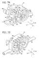
- FIGS. 7A and 7B are perspective views of the clamp 64.
- the clamp 64 is in a pre-locking state in FIG. 7A , and is closed to come in the state of closing the first tube 56 in FIG. 7B .
- the clamp 64 includes: a base section 142 provided with a locking section 140; an opening/closing section 146 provided with a protrusion section 144; and a bent section 148 which interconnects the base section 142 and the opening/closing section 146.
- the base section 142, the opening/closing section 146 and the bent section 148 are formed integrally.
- the extending direction of the base section 142 will be referred to as X direction
- the widthwise direction of the base section 142 that is orthogonal to the X direction will be referred to as Y direction
- the direction orthogonal to both the X direction and the Y direction will be referred to as Z direction.
- the clamp 64 is composed of a resin-made member. While the base section 142, the bent section 148 and the opening/closing section 146 are shaped to be aligned on a straight line upon molding, the clamp 64 is elastically deformed so as to be bent at the portion of the bent section 148, thereby being shaped as shown in FIG. 7A or 7B .
- the base section 142 is plate-shaped as a whole, and is provided with the locking section 140 at an inner surface thereof.
- the locking section 140 has a first engagement section 150 and a second engagement section 152 which project substantially vertically (in the Z direction) from the inner surface of the base section 142. Between the first engagement section 150 and the second engagement section 152 is formed an engagement groove 154 into which the protrusion section 144 can be inserted.
- the first engagement section 150 and the second engagement section 152 are formed at their tips with engagement claws 150a and 152a which are projecting to the engagement groove 154 side and are capable of engagement with the protrusion section 144.
- the first engagement section 150 and the second engagement section 152 are provided in their base portions with through-holes 150b and 152b which are bored along the extending direction (X direction) of the base section 142 and are so sized that the first tube 56 can be inserted therethrough.
- the bent section 148 is provided with a through-hole 148a which extends along the extending direction of the bent section 148, is penetrating the bent section 148 in the thickness direction of the bent section 148, and is so sized that the first tube 56 can be inserted therethrough.
- the first engagement release section 156 in the configuration example shown is formed to be bent from the tip of the first engagement section 150 and to extend in such a direction as to come away from the second engagement section 152.
- the first engagement release section 156 In an engaged state between the protrusion section 144 and the locking section 140, the first engagement release section 156 is located between the base section 142 and the opening/closing section 146.
- a first hook piece 160 At the tip of the first engagement release section 156 is provided a first hook piece 160 which is bent outward and is capable of engagement with the second pressing element 134 of the clamp operating section 124.
- the first engagement release section 156 may be provided not at the tip of the first engagement section 150 but at an intermediate position in the extending direction (Z direction) of the first engagement section 150.
- the second engagement release section 158 is formed to be bent from the tip of the second engagement section 152 and to extend toward the bent section 148 side.
- a second hook piece 162 capable of engagement with a release pin 166 (see FIG. 8 ) for putting the second engagement release section 158 into a releasing state.
- the second hook piece 162 in the example shown is formed to be bent to the Z2 direction side at a tip portion of the second engagement release section 158.
- the second engagement release section 158 may be provided not at the tip of the second engagement section 152 but at an intermediate position in the extending direction (Z direction) of the second engagement section 152.
- the opening/closing section 146 is plate-shaped as a whole, and the protrusion section 144 for pressing the first tube 56 is provided roughly vertically at an inner surface of the opening/closing section 146.
- the opening/closing section 146 is provided with an opening section 164 for partly exposing the first engagement release section 156 so as to be capable of pressing the first engagement release section 156 from outside.
- the opening section 164 according to the configuration example shown is formed as a cutout provided on width-directionally (X-directionally) one side of the opening/closing section 146, but this configuration is not restrictive.
- the opening section 164 may be formed as an opening which penetrates the opening/closing section 146 in the thickness direction (Y direction) of the latter.
- the protrusion section 144 is provided at its one side surface with a claw section 144a capable of engagement with the engagement claw 150a of the first engagement section 150.
- the protrusion section 144 is provided at its other side surface with two claw sections 144b and 144c capable of engagement with the engagement claw 152a of the second engagement section 152.
- the claw section 144c is provided on the side of the tip of the protrusion section 144 relative to the claw section 144b.
- the protrusion section 144 When the protrusion section 144 is inserted into the engagement groove 154 to such a position that the engagement claws 150a and 152a of the first engagement section 150 and the second engagement section 152 are engaged with the claw sections 144a and 144b of the protrusion section 144, as shown in FIG. 7B , the first tube 56 is pressed by the protrusion section 144 and the flow path in the first tube 56 is put into a closed state.
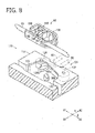
- FIG. 8 is a partly omitted schematic perspective view showing the configuration of a clamp opening and closing mechanism 170 provided in the tube holder 118.
- the clamp opening and closing mechanism 170 includes a clamp holding section 122 for holding and positioning the clamp 64, the release pin 166 provided on the clamp holding section 122, and a clamp operating section 124 for operations of opening and closing the clamp 64.
- the release pin 166 is a member which is projected upward from a bottom surface of the clamp holding section 122 and is formed with a taper surface 166a at a tip portion thereof.
- the release pin 166 has a function of pressing the second engagement release section 158 of the clamp 64 mounted to the clamp holding section 122 in a lateral direction (B2 direction), thereby to displace the second engagement section 152 to an engagement released position.
- the clamp operating section 124 has the first pressing element 132 and the second pressing element 134, as above-mentioned.
- the first pressing element 132 is swung by an operation of the first rod 90, to press the opening/closing section 146 in; on the other hand, the second pressing element 134 is swung by an operation of the second rod 92, to incline the first engagement release section 156,
- the first pressing element 132 and the second pressing element 134 are rotatably supported on the tube holder 118 through the pins 128 and 130, respectively, and are biased in the A2 direction by springs (not shown).
- springs not shown
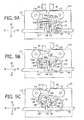
- FIGS. 9A to 9C are schematic operation illustrations showing the manner in which the clamp 64 is opened by the clamp opening and closing mechanism 170.
- the second engagement release section 158 is pressed by the release pin 166, and the second engagement section 152 is elastically deformed and displaced in the B2 direction.
- the second engagement release section 158 is guided by the taper surface 166a provided at an upper portion of the release pin 166, so that the mounting of the clamp 64 to the clamp holding section 122 can be carried out smoothly.
- the second engagement section 152 With the second engagement section 152 thus displaced in the B2 direction, the engagement claw 152a of the second engagement section 152 is released from the claw section 144b of the protrusion section 144, and the second engagement section 152 is put into an engagement released state. Therefore, in the condition where the clamp 64 is mounted to the clamp holding section 122, the second engagement section 152 of the clamp 64 is always in the engagement released state.
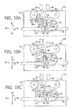
- FIGS. 10A to 10C are schematic operation illustrations showing the manner in which the clamp 64 is opened by the clamp opening and closing mechanism 170.
- the second rod 92 is retracted, as shown in FIG. 10A , the second pressing element 134 is returned into its original position, and the first engagement release section 156 is also returned in its original position.
- the first rod 90 is advanced, starting from this condition, the first pressing element 132 is turned to press the opening/closing section 146 of the clamp 64 in the A1 direction.
- the protrusion section 144 is inserted to a deep position in the engagement groove 154, and the engagement claw 150a of the first engagement section 150 is engaged with the claw section 144a of the protrusion section 144, whereby the protrusion section 144 is locked by the first engagement section 150.
- the locking of the protrusion section 144 by the locking section 140 is not released unless both the engagement of the first engagement release section 156 and the engagement of the second engagement release section 158 are released. Therefore, the closed state of the first tube 56 can be maintained assuredly and stably.
- the second engagement release section 158 Since the second engagement release section 158 is provided between the protrusion section 144 and the bent section 148, it is hard to operate by the fingers of the person who handles the clamp 64. With the second engagement release section 158 thus located in a position where it is hard to operate, the closed state of the first tube 56 can be maintained further assuredly.
- the second engagement release section 158 is put into an engagement releasing state by engagement of the second hook piece 162 with the release pin 166. Therefore, the second engagement release section 158 can be smoothly put into the engagement releasing state by an action of the second hook piece 162.
- the first engagement release section 156 is bent from the tip of the first engagement section 150 and extends in such a direction as to come away from the second engagement section 152.
- the first engagement release section 156 is located between the base section 142 and the opening/closing section 146; therefore, it is hard to operate by the fingers of the person who handles the clamp 64. With the first engagement release section 156 thus located in a position where it is hard to operate, the closed state of the first tube 56 can be maintained more reliably.
- the opening/closing section 146 is provided with the opening section 164 which enables the first engagement release section 156 to be pressed from outside. Therefore, the first engagement release section 156 can be pressed from outside of the opening/closing section 146 through the opening section 164. Accordingly, even in the case where means for operating the first engagement release section 156 is provided at a position outside of the first engagement release section 156, the first engagement release section 156 can be easily put into the releasing state.
- the clamp 64 which can be stably maintained in a locked state and can be opened when necessary is attached to the first tube 56. Therefore, it is possible, by opening and closing the flow path in the first tube 56, to switch the communication condition between the primary bag 50 and the sub bag 52, and thereby to suitably carry out desired blood treatments.
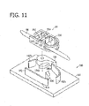
- the clamp 64 can not only be opened by the clamp opening and closing mechanism 170 provided in the tube holder 118 as above-mentioned, but also be opened by use of a clamp opening jig 180 as shown in FIG. 11 .
- the clamp opening jig 180 includes a base plate 181, a clamp holding section 182 for positioning and fixing the clamp 64, a pressing element 184 for pressing the first engagement release section 156, and a release pin 186 for pressing the second engagement release section 158.
- the clamp holding section 182 in the clamp opening jig 180 has a function of mounting the clamp 64 and fixing the clamp 64 so as to prevent the clamp 64 from moving out of position, like the clamp holding section 122 in the clamp opening and closing mechanism 170.
- the clamp holding section 182 according to one configuration example is composed of three walls 182a, 182b and 182c projected from the base plate 181; however, the clamp holding section may be composed of a groove or grooves opening to the upper side, like the clamp holding section 122.
- the release pin 186 is configured in the same manner as the release pin 166 in the clamp opening and closing mechanism 170.
- the pressing element 184 is configured in the same manner as the second pressing element 134 in the clamp opening and closing mechanism 170, and has a release claw 184a configured in the same manner as the release claw 134a.
- the clamp 64 When the clamp 64 is mounted to such a clamp opening jig 180, the second engagement release section 158 is pressed by the release pin 186, whereby the second engagement section 152 is put into a disengaged state.
- the pressing element 184 When the pressing element 184 is then pressed by a finger, the first engagement release section 156 is pressed by the release claw 184a, whereby the first engagement section 150 is put into a disengaged state, and the clamp 64 is opened.
- the clamp opening jig 180 it is possible to open the clamp 64, without need to mount the clamp 64 to the tube holder 118. Therefore, even in the case where it becomes necessary, for some reason, to open the clamp 64 at a stage prior to mounting the clamp 64 to the tube holder 118, the clamp 64 can be opened easily and speedily without any needless operation.
- the clamp 64 is provided on the tube (first tube 56) in a multiple bag (separating treatment section 16) inclusive of the primary bag 50, the sub bag 52 and the additive solution bag 54 in this embodiment, the clamp 64 may be provided on a tube in a blood bag system 10 of other form. Accordingly, the clamp 64 may be provided, for example, a tube in a blood bag system used for separating whole blood into three components including plasma, buffy coat and concentrated red blood cells.
- clamp 64 in the present Invention may be used as the clamps 30, 36 and 48.
- the clamp 64 may be provided also on the second tube 58 and on the third tube 60.
Landscapes
- Health & Medical Sciences (AREA)
- Heart & Thoracic Surgery (AREA)
- Life Sciences & Earth Sciences (AREA)
- Veterinary Medicine (AREA)
- Public Health (AREA)
- General Health & Medical Sciences (AREA)
- Animal Behavior & Ethology (AREA)
- Engineering & Computer Science (AREA)
- Hematology (AREA)
- Biomedical Technology (AREA)
- Anesthesiology (AREA)
- Pulmonology (AREA)
- Vascular Medicine (AREA)
- Pharmacology & Pharmacy (AREA)
- External Artificial Organs (AREA)
Applications Claiming Priority (2)
| Application Number | Priority Date | Filing Date | Title |
|---|---|---|---|
| JP2010149782 | 2010-06-30 | ||
| PCT/JP2011/061768 WO2012002067A1 (fr) | 2010-06-30 | 2011-05-23 | Système de clamp et de poche de sang |
Publications (3)
| Publication Number | Publication Date |
|---|---|
| EP2589395A1 true EP2589395A1 (fr) | 2013-05-08 |
| EP2589395A4 EP2589395A4 (fr) | 2018-03-21 |
| EP2589395B1 EP2589395B1 (fr) | 2021-11-10 |
Family
ID=45401801
Family Applications (1)
| Application Number | Title | Priority Date | Filing Date |
|---|---|---|---|
| EP11800536.2A Active EP2589395B1 (fr) | 2010-06-30 | 2011-05-23 | Système de clamp et de poche de sang |
Country Status (5)
| Country | Link |
|---|---|
| US (1) | US9060920B2 (fr) |
| EP (1) | EP2589395B1 (fr) |
| JP (1) | JP5801301B2 (fr) |
| CN (2) | CN102971021B (fr) |
| WO (1) | WO2012002067A1 (fr) |
Cited By (2)
| Publication number | Priority date | Publication date | Assignee | Title |
|---|---|---|---|---|
| WO2017074681A1 (fr) * | 2015-10-28 | 2017-05-04 | Becton, Dickinson And Company | Dispositif de pince de serrage |
| US10589082B2 (en) | 2016-02-17 | 2020-03-17 | Becton, Dickinson And Company | Pinch clamp |
Families Citing this family (14)
| Publication number | Priority date | Publication date | Assignee | Title |
|---|---|---|---|---|
| JP5989554B2 (ja) * | 2012-02-07 | 2016-09-07 | 川澄化学工業株式会社 | クランプ及び医療用具 |
| US9829113B2 (en) | 2012-05-25 | 2017-11-28 | Nxstage Medical, Inc. | Clamp device and methods for making and using |
| JP5989231B2 (ja) * | 2013-04-01 | 2016-09-07 | テルモ株式会社 | クランプ |
| WO2016134317A1 (fr) | 2015-02-20 | 2016-08-25 | Terumo Bct, Inc. | Support de système de poche de liquide composite |
| CN106267461A (zh) * | 2015-05-28 | 2017-01-04 | 广东龙心医疗器械有限公司 | 一种止液夹 |
| CN110035779B (zh) | 2016-12-02 | 2022-05-13 | 泰尔茂比司特公司 | 复合流体分离 |
| US10639417B2 (en) * | 2017-10-25 | 2020-05-05 | Carefusion 303, Inc. | Lever for auto insertion and secure placement of IV tubing for use in intravenous pump systems |
| JP7382711B2 (ja) * | 2018-11-01 | 2023-11-17 | テルモ株式会社 | 細胞成分採取システムおよび細胞成分採取方法 |
| CN109806449B (zh) * | 2019-03-04 | 2022-01-04 | 郝东方 | 一种医用集尿袋 |
| CN113453735A (zh) * | 2019-03-14 | 2021-09-28 | 泰尔茂株式会社 | 血袋系统 |
| JP6840894B1 (ja) * | 2019-03-27 | 2021-03-10 | テルモ株式会社 | 血液バッグシステム及びクランプ |
| US11495952B2 (en) * | 2019-09-18 | 2022-11-08 | Erico International Corporation | Bracket system for mounting electrical boxes |
| US12044335B2 (en) * | 2020-12-08 | 2024-07-23 | Sartorius Stedim North America Inc. | Pinch clamp for flexible conduits |
| CN115054525A (zh) * | 2022-06-29 | 2022-09-16 | 孔维强 | 奶瓶 |
Family Cites Families (17)
| Publication number | Priority date | Publication date | Assignee | Title |
|---|---|---|---|---|
| US4557727A (en) * | 1982-04-23 | 1985-12-10 | Handt Alan E | Spike exchanger for continuous ambulatory peritoneal dialysis |
| US4807622A (en) * | 1985-09-20 | 1989-02-28 | Kato Hatsujo Kaisha, Ltd. | Tube cutting and separating implement for conduit of blood or the like |
| US4804363A (en) * | 1986-07-16 | 1989-02-14 | Autologous Blood Corporation | Apparatus and method for storing and processing blood |
| JPH024384A (ja) * | 1988-06-14 | 1990-01-09 | Terumo Corp | クランプ |
| JPH0217142U (fr) * | 1989-07-04 | 1990-02-05 | ||
| GB9123305D0 (en) * | 1991-11-04 | 1991-12-18 | Haemocell Plc | Improvements relating to the mixing of fluids |
| JPH0523792A (ja) | 1991-07-24 | 1993-02-02 | Daikin Ind Ltd | 中空構造体の製造方法 |
| JPH0671474B2 (ja) * | 1991-12-18 | 1994-09-14 | 川澄化学工業株式会社 | クランプ付血液バッグ |
| US6592558B2 (en) * | 2000-12-28 | 2003-07-15 | Baxter International Inc. | Clamp device, method and system for exchanging a solution |
| DE10065283A1 (de) | 2000-12-29 | 2002-07-04 | Hettich Andreas Gmbh & Co Kg | Zentrifuge mit Blutbeutelsystem mit oberem und unterem Abgang |
| US8262639B2 (en) * | 2002-01-31 | 2012-09-11 | Fenwal, Inc. | Irreversible flow control clamp |
| WO2003063930A1 (fr) * | 2002-02-01 | 2003-08-07 | Gambro, Inc. | Procede de prelevement et de traitement de sang total |
| US20040089828A1 (en) * | 2002-10-18 | 2004-05-13 | Werth Albert A. | Conduit clamp |
| DE102004001461A1 (de) * | 2004-01-08 | 2005-08-11 | Wollschläger, Helmut, Prof. Dr.med. | Vorrichtung zur Handhabung eines Katheters |
| US7124996B2 (en) * | 2004-07-16 | 2006-10-24 | Cardinal Health 303, Inc. | Automatic clamp apparatus for IV infusion sets used in pump devices |
| CN100558417C (zh) * | 2004-10-19 | 2009-11-11 | 泰尔茂株式会社 | 输液装置及夹子 |
| DE102005004863A1 (de) * | 2005-02-02 | 2006-08-03 | Fresenius Medical Care Deutschland Gmbh | Schlauchklemme |
-
2011
- 2011-05-23 CN CN201180032737.6A patent/CN102971021B/zh active Active
- 2011-05-23 CN CN201610860456.4A patent/CN107029345B/zh active Active
- 2011-05-23 JP JP2012522513A patent/JP5801301B2/ja active Active
- 2011-05-23 EP EP11800536.2A patent/EP2589395B1/fr active Active
- 2011-05-23 WO PCT/JP2011/061768 patent/WO2012002067A1/fr not_active Ceased
-
2012
- 2012-12-20 US US13/722,447 patent/US9060920B2/en active Active
Non-Patent Citations (1)
| Title |
|---|
| See references of WO2012002067A1 * |
Cited By (6)
| Publication number | Priority date | Publication date | Assignee | Title |
|---|---|---|---|---|
| WO2017074681A1 (fr) * | 2015-10-28 | 2017-05-04 | Becton, Dickinson And Company | Dispositif de pince de serrage |
| US11040186B2 (en) | 2015-10-28 | 2021-06-22 | Becton, Dickinson And Company | Pinch clamp device |
| US11724088B2 (en) | 2015-10-28 | 2023-08-15 | Becton, Dickinson And Company | Pinch clamp device |
| US10589082B2 (en) | 2016-02-17 | 2020-03-17 | Becton, Dickinson And Company | Pinch clamp |
| US11628290B2 (en) | 2016-02-17 | 2023-04-18 | Becton, Dickinson And Company | Pinch clamp |
| US12194269B2 (en) | 2016-02-17 | 2025-01-14 | Becton, Dickinson And Company | Pinch clamp |
Also Published As
| Publication number | Publication date |
|---|---|
| CN107029345A (zh) | 2017-08-11 |
| US9060920B2 (en) | 2015-06-23 |
| CN102971021A (zh) | 2013-03-13 |
| CN102971021B (zh) | 2016-10-12 |
| US20130123740A1 (en) | 2013-05-16 |
| EP2589395A4 (fr) | 2018-03-21 |
| JP5801301B2 (ja) | 2015-10-28 |
| WO2012002067A1 (fr) | 2012-01-05 |
| JPWO2012002067A1 (ja) | 2013-08-22 |
| EP2589395B1 (fr) | 2021-11-10 |
| CN107029345B (zh) | 2020-03-06 |
Similar Documents
| Publication | Publication Date | Title |
|---|---|---|
| EP2589395B1 (fr) | Système de clamp et de poche de sang | |
| US10238781B2 (en) | Blood bag system and blood treatment method | |
| JP6218873B2 (ja) | クランプおよび血液バッグシステム | |
| EP2349395B1 (fr) | Systeme et cassette de poche de sang | |
| US20110238029A1 (en) | Blood bag system and cassette | |
| JP5977444B2 (ja) | 血液バッグシステム | |
| US20160317727A1 (en) | Blood Bag System and Tube Holder | |
| JP6943952B2 (ja) | 血液バッグシステム及び血液処理方法 |
Legal Events
| Date | Code | Title | Description |
|---|---|---|---|
| PUAI | Public reference made under article 153(3) epc to a published international application that has entered the european phase |
Free format text: ORIGINAL CODE: 0009012 |
|
| 17P | Request for examination filed |
Effective date: 20130107 |
|
| AK | Designated contracting states |
Kind code of ref document: A1 Designated state(s): AL AT BE BG CH CY CZ DE DK EE ES FI FR GB GR HR HU IE IS IT LI LT LU LV MC MK MT NL NO PL PT RO RS SE SI SK SM TR |
|
| DAX | Request for extension of the european patent (deleted) | ||
| RA4 | Supplementary search report drawn up and despatched (corrected) |
Effective date: 20180221 |
|
| RIC1 | Information provided on ipc code assigned before grant |
Ipc: A61M 5/168 20060101ALI20180214BHEP Ipc: A61M 1/02 20060101AFI20180214BHEP Ipc: A61M 39/28 20060101ALI20180214BHEP |
|
| STAA | Information on the status of an ep patent application or granted ep patent |
Free format text: STATUS: EXAMINATION IS IN PROGRESS |
|
| 17Q | First examination report despatched |
Effective date: 20191029 |
|
| GRAP | Despatch of communication of intention to grant a patent |
Free format text: ORIGINAL CODE: EPIDOSNIGR1 |
|
| STAA | Information on the status of an ep patent application or granted ep patent |
Free format text: STATUS: GRANT OF PATENT IS INTENDED |
|
| INTG | Intention to grant announced |
Effective date: 20210521 |
|
| GRAS | Grant fee paid |
Free format text: ORIGINAL CODE: EPIDOSNIGR3 |
|
| GRAA | (expected) grant |
Free format text: ORIGINAL CODE: 0009210 |
|
| STAA | Information on the status of an ep patent application or granted ep patent |
Free format text: STATUS: THE PATENT HAS BEEN GRANTED |
|
| AK | Designated contracting states |
Kind code of ref document: B1 Designated state(s): AL AT BE BG CH CY CZ DE DK EE ES FI FR GB GR HR HU IE IS IT LI LT LU LV MC MK MT NL NO PL PT RO RS SE SI SK SM TR |
|
| REG | Reference to a national code |
Ref country code: GB Ref legal event code: FG4D |
|
| REG | Reference to a national code |
Ref country code: AT Ref legal event code: REF Ref document number: 1445464 Country of ref document: AT Kind code of ref document: T Effective date: 20211115 Ref country code: CH Ref legal event code: EP |
|
| REG | Reference to a national code |
Ref country code: DE Ref legal event code: R096 Ref document number: 602011072087 Country of ref document: DE |
|
| REG | Reference to a national code |
Ref country code: IE Ref legal event code: FG4D |
|
| REG | Reference to a national code |
Ref country code: LT Ref legal event code: MG9D |
|
| REG | Reference to a national code |
Ref country code: NL Ref legal event code: MP Effective date: 20211110 |
|
| REG | Reference to a national code |
Ref country code: AT Ref legal event code: MK05 Ref document number: 1445464 Country of ref document: AT Kind code of ref document: T Effective date: 20211110 |
|
| PG25 | Lapsed in a contracting state [announced via postgrant information from national office to epo] |
Ref country code: RS Free format text: LAPSE BECAUSE OF FAILURE TO SUBMIT A TRANSLATION OF THE DESCRIPTION OR TO PAY THE FEE WITHIN THE PRESCRIBED TIME-LIMIT Effective date: 20211110 Ref country code: LT Free format text: LAPSE BECAUSE OF FAILURE TO SUBMIT A TRANSLATION OF THE DESCRIPTION OR TO PAY THE FEE WITHIN THE PRESCRIBED TIME-LIMIT Effective date: 20211110 Ref country code: FI Free format text: LAPSE BECAUSE OF FAILURE TO SUBMIT A TRANSLATION OF THE DESCRIPTION OR TO PAY THE FEE WITHIN THE PRESCRIBED TIME-LIMIT Effective date: 20211110 Ref country code: BG Free format text: LAPSE BECAUSE OF FAILURE TO SUBMIT A TRANSLATION OF THE DESCRIPTION OR TO PAY THE FEE WITHIN THE PRESCRIBED TIME-LIMIT Effective date: 20220210 Ref country code: AT Free format text: LAPSE BECAUSE OF FAILURE TO SUBMIT A TRANSLATION OF THE DESCRIPTION OR TO PAY THE FEE WITHIN THE PRESCRIBED TIME-LIMIT Effective date: 20211110 |
|
| PG25 | Lapsed in a contracting state [announced via postgrant information from national office to epo] |
Ref country code: IS Free format text: LAPSE BECAUSE OF FAILURE TO SUBMIT A TRANSLATION OF THE DESCRIPTION OR TO PAY THE FEE WITHIN THE PRESCRIBED TIME-LIMIT Effective date: 20220310 Ref country code: SE Free format text: LAPSE BECAUSE OF FAILURE TO SUBMIT A TRANSLATION OF THE DESCRIPTION OR TO PAY THE FEE WITHIN THE PRESCRIBED TIME-LIMIT Effective date: 20211110 Ref country code: PT Free format text: LAPSE BECAUSE OF FAILURE TO SUBMIT A TRANSLATION OF THE DESCRIPTION OR TO PAY THE FEE WITHIN THE PRESCRIBED TIME-LIMIT Effective date: 20220310 Ref country code: PL Free format text: LAPSE BECAUSE OF FAILURE TO SUBMIT A TRANSLATION OF THE DESCRIPTION OR TO PAY THE FEE WITHIN THE PRESCRIBED TIME-LIMIT Effective date: 20211110 Ref country code: NO Free format text: LAPSE BECAUSE OF FAILURE TO SUBMIT A TRANSLATION OF THE DESCRIPTION OR TO PAY THE FEE WITHIN THE PRESCRIBED TIME-LIMIT Effective date: 20220210 Ref country code: NL Free format text: LAPSE BECAUSE OF FAILURE TO SUBMIT A TRANSLATION OF THE DESCRIPTION OR TO PAY THE FEE WITHIN THE PRESCRIBED TIME-LIMIT Effective date: 20211110 Ref country code: LV Free format text: LAPSE BECAUSE OF FAILURE TO SUBMIT A TRANSLATION OF THE DESCRIPTION OR TO PAY THE FEE WITHIN THE PRESCRIBED TIME-LIMIT Effective date: 20211110 Ref country code: HR Free format text: LAPSE BECAUSE OF FAILURE TO SUBMIT A TRANSLATION OF THE DESCRIPTION OR TO PAY THE FEE WITHIN THE PRESCRIBED TIME-LIMIT Effective date: 20211110 Ref country code: GR Free format text: LAPSE BECAUSE OF FAILURE TO SUBMIT A TRANSLATION OF THE DESCRIPTION OR TO PAY THE FEE WITHIN THE PRESCRIBED TIME-LIMIT Effective date: 20220211 Ref country code: ES Free format text: LAPSE BECAUSE OF FAILURE TO SUBMIT A TRANSLATION OF THE DESCRIPTION OR TO PAY THE FEE WITHIN THE PRESCRIBED TIME-LIMIT Effective date: 20211110 |
|
| PG25 | Lapsed in a contracting state [announced via postgrant information from national office to epo] |
Ref country code: SM Free format text: LAPSE BECAUSE OF FAILURE TO SUBMIT A TRANSLATION OF THE DESCRIPTION OR TO PAY THE FEE WITHIN THE PRESCRIBED TIME-LIMIT Effective date: 20211110 Ref country code: SK Free format text: LAPSE BECAUSE OF FAILURE TO SUBMIT A TRANSLATION OF THE DESCRIPTION OR TO PAY THE FEE WITHIN THE PRESCRIBED TIME-LIMIT Effective date: 20211110 Ref country code: RO Free format text: LAPSE BECAUSE OF FAILURE TO SUBMIT A TRANSLATION OF THE DESCRIPTION OR TO PAY THE FEE WITHIN THE PRESCRIBED TIME-LIMIT Effective date: 20211110 Ref country code: EE Free format text: LAPSE BECAUSE OF FAILURE TO SUBMIT A TRANSLATION OF THE DESCRIPTION OR TO PAY THE FEE WITHIN THE PRESCRIBED TIME-LIMIT Effective date: 20211110 Ref country code: DK Free format text: LAPSE BECAUSE OF FAILURE TO SUBMIT A TRANSLATION OF THE DESCRIPTION OR TO PAY THE FEE WITHIN THE PRESCRIBED TIME-LIMIT Effective date: 20211110 Ref country code: CZ Free format text: LAPSE BECAUSE OF FAILURE TO SUBMIT A TRANSLATION OF THE DESCRIPTION OR TO PAY THE FEE WITHIN THE PRESCRIBED TIME-LIMIT Effective date: 20211110 |
|
| REG | Reference to a national code |
Ref country code: DE Ref legal event code: R097 Ref document number: 602011072087 Country of ref document: DE |
|
| PLBE | No opposition filed within time limit |
Free format text: ORIGINAL CODE: 0009261 |
|
| STAA | Information on the status of an ep patent application or granted ep patent |
Free format text: STATUS: NO OPPOSITION FILED WITHIN TIME LIMIT |
|
| 26N | No opposition filed |
Effective date: 20220811 |
|
| PG25 | Lapsed in a contracting state [announced via postgrant information from national office to epo] |
Ref country code: AL Free format text: LAPSE BECAUSE OF FAILURE TO SUBMIT A TRANSLATION OF THE DESCRIPTION OR TO PAY THE FEE WITHIN THE PRESCRIBED TIME-LIMIT Effective date: 20211110 |
|
| PG25 | Lapsed in a contracting state [announced via postgrant information from national office to epo] |
Ref country code: SI Free format text: LAPSE BECAUSE OF FAILURE TO SUBMIT A TRANSLATION OF THE DESCRIPTION OR TO PAY THE FEE WITHIN THE PRESCRIBED TIME-LIMIT Effective date: 20211110 |
|
| REG | Reference to a national code |
Ref country code: CH Ref legal event code: PL |
|
| REG | Reference to a national code |
Ref country code: BE Ref legal event code: MM Effective date: 20220531 |
|
| PG25 | Lapsed in a contracting state [announced via postgrant information from national office to epo] |
Ref country code: MC Free format text: LAPSE BECAUSE OF FAILURE TO SUBMIT A TRANSLATION OF THE DESCRIPTION OR TO PAY THE FEE WITHIN THE PRESCRIBED TIME-LIMIT Effective date: 20211110 Ref country code: LU Free format text: LAPSE BECAUSE OF NON-PAYMENT OF DUE FEES Effective date: 20220523 Ref country code: LI Free format text: LAPSE BECAUSE OF NON-PAYMENT OF DUE FEES Effective date: 20220531 Ref country code: CH Free format text: LAPSE BECAUSE OF NON-PAYMENT OF DUE FEES Effective date: 20220531 |
|
| REG | Reference to a national code |
Ref country code: FR Ref legal event code: PLFP Year of fee payment: 13 |
|
| PG25 | Lapsed in a contracting state [announced via postgrant information from national office to epo] |
Ref country code: IE Free format text: LAPSE BECAUSE OF NON-PAYMENT OF DUE FEES Effective date: 20220523 |
|
| PG25 | Lapsed in a contracting state [announced via postgrant information from national office to epo] |
Ref country code: IT Free format text: LAPSE BECAUSE OF FAILURE TO SUBMIT A TRANSLATION OF THE DESCRIPTION OR TO PAY THE FEE WITHIN THE PRESCRIBED TIME-LIMIT Effective date: 20211110 Ref country code: BE Free format text: LAPSE BECAUSE OF NON-PAYMENT OF DUE FEES Effective date: 20220531 |
|
| PG25 | Lapsed in a contracting state [announced via postgrant information from national office to epo] |
Ref country code: HU Free format text: LAPSE BECAUSE OF FAILURE TO SUBMIT A TRANSLATION OF THE DESCRIPTION OR TO PAY THE FEE WITHIN THE PRESCRIBED TIME-LIMIT; INVALID AB INITIO Effective date: 20110523 |
|
| PG25 | Lapsed in a contracting state [announced via postgrant information from national office to epo] |
Ref country code: MK Free format text: LAPSE BECAUSE OF FAILURE TO SUBMIT A TRANSLATION OF THE DESCRIPTION OR TO PAY THE FEE WITHIN THE PRESCRIBED TIME-LIMIT Effective date: 20211110 Ref country code: CY Free format text: LAPSE BECAUSE OF FAILURE TO SUBMIT A TRANSLATION OF THE DESCRIPTION OR TO PAY THE FEE WITHIN THE PRESCRIBED TIME-LIMIT Effective date: 20211110 |
|
| PG25 | Lapsed in a contracting state [announced via postgrant information from national office to epo] |
Ref country code: TR Free format text: LAPSE BECAUSE OF FAILURE TO SUBMIT A TRANSLATION OF THE DESCRIPTION OR TO PAY THE FEE WITHIN THE PRESCRIBED TIME-LIMIT Effective date: 20211110 |
|
| PG25 | Lapsed in a contracting state [announced via postgrant information from national office to epo] |
Ref country code: MT Free format text: LAPSE BECAUSE OF FAILURE TO SUBMIT A TRANSLATION OF THE DESCRIPTION OR TO PAY THE FEE WITHIN THE PRESCRIBED TIME-LIMIT Effective date: 20211110 |
|
| REG | Reference to a national code |
Ref country code: DE Ref legal event code: R084 Ref document number: 602011072087 Country of ref document: DE |
|
| PGFP | Annual fee paid to national office [announced via postgrant information from national office to epo] |
Ref country code: DE Payment date: 20250402 Year of fee payment: 15 |
|
| PGFP | Annual fee paid to national office [announced via postgrant information from national office to epo] |
Ref country code: GB Payment date: 20250401 Year of fee payment: 15 |
|
| PGFP | Annual fee paid to national office [announced via postgrant information from national office to epo] |
Ref country code: FR Payment date: 20250401 Year of fee payment: 15 |