EP2589415B1 - Flussformer zur Verwendung in Flursprinkler - Google Patents
Flussformer zur Verwendung in Flursprinkler Download PDFInfo
- Publication number
- EP2589415B1 EP2589415B1 EP12185798.1A EP12185798A EP2589415B1 EP 2589415 B1 EP2589415 B1 EP 2589415B1 EP 12185798 A EP12185798 A EP 12185798A EP 2589415 B1 EP2589415 B1 EP 2589415B1
- Authority
- EP
- European Patent Office
- Prior art keywords
- fluid
- shaper
- sprinkler assembly
- support
- flow
- Prior art date
- Legal status (The legal status is an assumption and is not a legal conclusion. Google has not performed a legal analysis and makes no representation as to the accuracy of the status listed.)
- Active
Links
Images
Classifications
-
- A—HUMAN NECESSITIES
- A62—LIFE-SAVING; FIRE-FIGHTING
- A62C—FIRE-FIGHTING
- A62C31/00—Delivery of fire-extinguishing material
- A62C31/02—Nozzles specially adapted for fire-extinguishing
Definitions
- the present disclosure relates to a sprinkler assembly and, more particularly, to a corridor sprinkler assembly that exhibits reduced energy losses.
- Conventional sprinkler assemblies include a base with a passageway, an inlet opening, and a discharge opening, which is adapted for connecting to the system piping, and a deflector that is supported spaced from the base, typically by a pair of frame arms that extend from the base.
- the frame arms are often joined at their distal ends by a boss, which is used to mount the deflector to the frame arms.
- the boss is typically aligned with the discharge opening of the base.
- Pendent sprinklers and upright sprinklers typically include deflectors with a solid central portion and a plurality of tines that extend radially outwardly from the central portion for dispersing the fluid as it flows across the solid central portion, which is mounted to the boss.
- Sidewall sprinklers typically include a deflector, also with a solid central portion with tines extending from the central portion and a blade that is positioned above the central portion to direct the fluid that flows above the central portion outwardly and downwardly. In each case, when the fluid flows from the discharge opening of the base the fluid impinges on the boss and on the central portion of the deflector.
- the boss and deflector disperse the fluid radially outward, relative to the axis of the discharge opening, and the fluid is thereafter further dispersed by the tines, and in the case of the sidewall sprinklers also by the blade. This results in a sizeable energy or head loss in the fluid at the sprinkler assembly.
- a sprinkler assembly that can disperse fluid with a reduced head loss may reduce the required pressure at the sprinkler assembly and, hence, provide cost savings for the installation of a fire protection system incorporating such sprinkler assemblies.
- WO 2006/107663 A2 describes a sprinkler assembly including a flow shaper member and a shelf portion, including the features of the preamble of claim 1.
- a corridor sprinkler includes a first flow shaper member supported by a support for shaping the flow of fluid from a sprinkler that includes a shelf portion having a proximal end and a distal end, the shelf being generally parallel to and spaced from the axis of the flow passage through the sprinkler body.
- a shield extends directly from the distal end of the shelf and generally perpendicular to the axis and partially intersecting the column of fluid without the support obstructing the column of fluid between the discharge opening and the shield.
- the shelf and the shield each have a width greater than a diameter of the discharge opening.
- a second flow shaper can extend from the support on an opposite side of the axis from the first flow shaper and partially intersecting the column of fluid.
- Example embodiments are provided so that this disclosure will be thorough, and will fully convey the scope to those who are skilled in the art. Numerous specific details are set forth such as examples of specific components, devices, and methods, to provide a thorough understanding of embodiments of the present disclosure. It will be apparent to those skilled in the art that specific details need not be employed, that example embodiments may be embodied in many different forms and that neither should be construed to limit the scope of the disclosure. In some example embodiments, well-known processes, well-known device structures, and well-known technologies are not described in detail.
- first, second, third, etc. may be used herein to describe various elements, components, regions, layers and/or sections, these elements, components, regions, layers and/or sections should not be limited by these terms. These terms may be only used to distinguish one element, component, region, layer or section from another region, layer or section. Terms such as “first,” “second,” and other numerical terms when used herein do not imply a sequence or order unless clearly indicated by the context. Thus, a first element, component, region, layer or section discussed below could be termed a second element, component, region, layer or section without departing from the teachings of the example embodiments.
- spatially relative terms such as “inner,” “outer,” “beneath,” “below,” “lower,” “above,” “upper,” and the like, may be used herein for ease of description to describe one element or feature's relationship to another element(s) or feature(s) as illustrated in the figures.
- Spatially relative terms may be intended to encompass different orientations of the device in use or operation in addition to the orientation depicted in the figures. For example, if the device in the figures is turned over, elements described as “below” or “beneath” other elements or features would then be oriented “above” the other elements or features.
- the example term “below” can encompass both an orientation of above and below.
- the device may be otherwise oriented (rotated 90 degrees or at other orientations) and the spatially relative descriptors used herein interpreted accordingly.
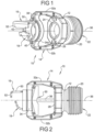
- the numeral 10 generally designates a sprinkler assembly of the present invention.
- sprinkler assembly 10 is configured and arranged to reduce the energy loss of the fluid as it flows from the sprinkler assembly 10.
- the term "fluid” is used broadly herein and includes substances that are capable of flowing, for example, water, foam, water/foam mixture, gas, powder, and other known fire suppressant materials.
- sprinkler assembly 10 is illustrated as a sidewall, corridor sprinkler assembly 10.
- the sprinkler of the present disclosure may be used in residential or commercial applications, including storage applications, and, further, may be configured to operate in a control mode or a suppression mode.
- the "K” factor may vary, where the “K” factor equals the flow of fluid, such as water, in liter per minute (gallons per minute) through the passageway divided by the square root of the pressure of fluid fed into the inlet of the sprinkler body in bar (pounds per square inch gauge).
- the "K” factor of the sprinkler assemblies of the present disclosure may be in a range of about 40.4 to 726.6 (2.8 to 50.4).
- the sprinkler assembly of the present disclosure may be configured as a fast response sprinkler as defined by the response time index.
- the response time index of a sprinkler is referred to as "RTI", which is a measure of the sensitivity of the thermal element of a sprinkler.
- RTI is usually determined by plunging a sprinkler into a heated laminar airflow within a test oven. RTI is calculated using operating time of the sprinkler, operating temperature of the sprinkler's heat-responsive element (as determined in a bath test), air temperature of the test oven, air velocity of the test oven, and the sprinkler's conductivity.
- Fast response sprinklers have an RTI typically less than 50 (m ⁇ s) 1/2 .
- the sprinkler assembly 10 of the present disclosure reduces the friction between the fluid and the sprinkler assembly and, hence, the energy loss of the fluid as it flows from the sprinkler assembly. Consequently, a sprinkler assembly of the present disclosure provides an optimally-sized sprinkler that will be able to cover greater areas for a given pressure than conventional sprinklers of the same size.
- sprinkler assembly 10 includes a sprinkler body 12, a support 14 that extends from body 12, and upper and lower fluid flow-shaper members 16, 18.
- Body 12 and support 14 preferably comprise an integrally formed unitary brass casting. Though, it should be understood that the body 12 and support 14 may be separately formed and, further, may be formed from other materials and by other forming methods.
- Body 12 comprises a generally tubular body that can have a threaded portion 20 for connecting the sprinkler assembly to a fluid supply line and, further, includes an inlet opening 22, a discharge opening 24, and a fluid passageway 26.
- Passageway 26 extends between inlet opening 22 through threaded portion 20 to discharge opening 24 so that when body 12 is coupled to the supply line and sprinkler assembly 10 is opened or actuated, such as in the case of a fire, fluid will flow from inlet opening 22 through passageway 26 and out from discharge opening 24.
- sprinkler assembly 10 further includes a closure device (28) releasably positioned at discharge opening 24 of body 12 to close passageway 26.
- a heat responsive trigger 30 is mounted in a manner to releasably retain closure device 28 at discharge opening 24 of body 12 to thereby maintain passageway 26 closed until trigger 30 is activated.
- support 14 is configured to allow at least a portion and, optionally most, if not all, of the fluid to flow through support 14 rather than into and around the support 14.
- at least a portion, and optionally most of the fluid flows between upper and lower flow-shaper members 16, 18, which direct and shape the fluid in a desired pattern in contrast to conventional sprinkler assemblies that typically include frames and deflectors that deflect and redirect the fluid and form barriers around which the fluid must flow.
- support 14 comprises a frame that includes a pair of arms 32a and 32b and a transverse member 34 that joins the ends of arms 32a and 32b and which is spaced from discharge opening 24. Arms 32a and 32b extend generally away from discharge opening 24 on opposed sides of body 12 and, as noted, are joined by transverse member 34. While two symmetrically positioned arms are illustrated, it should be understood that support 14 may include one, two, three, or four or more arms, for example three or four arms that are all symmetrically positioned around and spaced away from axis 36 of the passageway 26. As would be understood by those skilled in the art, support 14 is substantially rigid so as to provide support for the flow-shaper members 16, 18 and, further, support for a heat responsive trigger 30, as will be more fully described below.
- transverse member 34 of support 14 comprises an annular portion 34a and a pair of bosses 38, 40 that align and mount the annular portion 34a between arms 32a and 32b.
- the annular portion 34a provides an opening 42 with a center axis that is at least generally aligned along longitudinal axis 36 of sprinkler assembly 10 and spaced from discharge opening 24.
- the opening 42 can be round, square, rectangular, oblong, or another shape.
- axis 36 comprises a generally central axis that passes through the centers of the inlet and discharge openings.
- the alignment of the discharge opening 24 and opening 42 in the transverse member 34 allows the body 12 and support 14 to be integrally molded by a casting process wherein a single core member or a pair of coaxial core members can be utilized to co-axially form the openings 24 and 42.
- the opening or the innermost diameter 42 of the annular member is at least 0.4 inches (1,016 cm) in diameter and, more typically, in a range of about 0.5 to 2.5 inches (1,27cm to 6,35cm) in diameter. Further, opening 42 may be at least as large in diameter as discharge opening 24 and, further, may be larger in diameter than discharge opening 24. In this manner, the flow of fluid from body 12 is substantially unimpeded by support 14 and, instead, may flow through support 14 through opening 42. As a result, the flow of fluid is directed and shaped rather than redirected. Consequently, the energy loss of the fluid as it flows through the support 14 is reduced, if not eliminated. Furthermore, although opening 42 is depicted as a right cylindrical opening with a stepped side, the inner surface of opening 42 may be tapered inwardly or outwardly.
- upper and lower fluid flow-shaper members 16, 18 are located adjacent or at opening 42, and can be downstream of the opening 42 as shown. Further, flow-shaper members 16, 18 may be offset from axis 36 of the sprinkler head body so as not to intersect the axis 36.
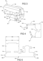
- the upper fluid flow-shaper member 16 includes an upper shelf portion 50 that is generally parallel to the longitudinal axis 36 of the sprinkler head body and a shield portion 52 generally perpendicular to the longitudinal axis 36.
- the upper shelf portion 50 is approximately two degrees from parallel.
- the upper shelf portion 50 can be planar in shape and can have a width (W1) greater than a diameter of the inner diameter of the opening 42 of the transverse member 34 of the support 14.
- W1 width
- the upper shelf portion 50 can also be curved, angled, or otherwise bent as desired to provide a desired flow pattern.
- the shield 52 is attached to a distal end of the upper shelf 50.
- the shield can have a width (W2) generally equal to the width (W1) of the upper shelf portion 50.
- the shield 52 can be wider or narrower than the upper shelf portion depending upon a desired spray pattern of the sprinkler.
- the shield 52 can include a distal edge 54 having a protruding portion 56 and pair of recessed regions 58 flanking the protruding portion 56 and laterally inward from the outer edges 60 of the shield 52.
- the shape of the distal edge 58 can be modified to obtain a desired spray pattern for a specific application.
- the shield portion 52 of the upper fluid flow shaper 16 can extend toward the longitudinal axis 36 by a desired distance in order to provide a desired spray pattern. In the embodiment shown, the shield portion 52 does not intersect the longitudinal axis 36 and is spaced from the longitudinal axis 36.
- the lower fluid flow-shaper 18 extends upward from a lower edge of the opening 42 toward the longitudinal axis 36 and can have an arcuate shape at its origin and a planar shape at its distal end.
- the distal edge 62 of the lower flow-shaper 18 includes a central protruding portion 64.
- the lower flow-shaper 18 also can include a pair of tabs 66 extending rearwardly from lateral sides 68 of the flow-shaper 18.
- the shape of the lower fluid flow-shaper 18 can be modified to provide a desired spray pattern for a given application.
- the lower flow-shaper 18 can extend toward and be spaced from the longitudinal axis 36 by a distance less than the upper flow-shaper 16 is spaced from the longitudinal axis 36.
- sprinkler assembly 10 when fluid flows from discharge opening 24, the fluid generally forms a column of fluid, which is substantially unencumbered by any structure until it contacts flow-shaper members 16, 18.
- sprinkler assembly 10 has a flow path from discharge opening 24 that is unencumbered or unobstructed by support 14.
- flow-shaper members 16, 18, flow-shaper members 16, 18 operate on the column of fluid from its outer surface radially inward-in contrast to a conventional deflector and frame, which act as abutments and then redirect the fluid and spread the column of fluid generally from its center to fan the fluid radially outward and, thereafter, disperses the fluid as the fluid flows around the deflector.
- a conventional sprinkler the fluid experiences significant energy loss due to the friction and deflection between the fluid and the frame and the deflector.
- fluid flow-shaper members 16, 18 are formed as a pair of tabs that are mounted to or formed with an annular transverse member 34.
- the flow-shaper members 16, 18 can be attached to a ring 70.
- the fluid flow-shaper members 16, 18 are attached to support 14 by mounting ring member 70 in support 14.
- flow-shaper members 28 may alternatively be attached to support 14 by attaching flow-shaper members 28 to support 14, for example by welding the flow-shaper members to the support, such as to annular member 34a, or by integrally forming the support 14 with the flow-shaper members.
- Flow-shaper members 16, 18 can be formed, cut or otherwise machined into the support structure so as to be formed integrally therewith.
- tabs 16, 18 may be mounted by a member that mounts about support 14 and annular member 34 outwardly of opening 42.
- opening 42 of annular member 34 is preferably at least as large in diameter as discharge opening 24. In this manner, most, if not all, the fluid discharged from discharge opening 24 may flow through support 14 unimpeded by support 14 or annular member 34.
- trigger 30 is mounted so as to retain closure device 28 in position over discharge opening 20.
- trigger 36 comprises a heat sensitive member 36 that is mounted between support 14 and closure device 28, in a manner as described in commonly assigned U.S. Patent No. 7,854,269 . It should be understood that other trigger devices can also be used.
- flow-shaper members are provided by tabs 16, 18, which are formed or otherwise provided on an annular member 70.
- flow-shaper members 16, 18 may be formed with an annular member 70 as a blank 104, with opposed ends 106 and 108 of blank 104 including interlocking features, such as a tab 110 and a recess 112.
- annular member 70 may be provided with arcuate indentations or cut-outs 114 at its upper edge 116.
- the blank 104 is formed into a ring 70 so that tab 110 is received in recess 112.
- the upper flow shaper member 16 is then formed by bending the shield portion 52 approximately 90 degrees relative to the shelf portion 50 along the parting line 118.
- the shelf portion 50 can also be bent relative to the ring 70, as desired.
- the lower flow shaper member 18 can be bent or curved toward the central axis. The bending and forming steps can be performed by hand or by automated techniques using fixtures or stampings.
- the upper flow shaper member 16 can extend axially beyond the lower flow shaper member 18 by an amount that can be at least 30 percent and preferably approximately fifty percent further than the axial extent of the lower flow shaper member 18.
- the lower flow shaper member 18 is angled approximately relative to perpendicular to the central axis and can be in a plane intersecting a junction between the shelf 50 and shield 52.
- the width of the lower flow shaper member 18 can be narrower than an inner diameter of the opening 42.
Landscapes
- Health & Medical Sciences (AREA)
- Public Health (AREA)
- Business, Economics & Management (AREA)
- Emergency Management (AREA)
- Fire-Extinguishing By Fire Departments, And Fire-Extinguishing Equipment And Control Thereof (AREA)
- Nozzles (AREA)
Claims (10)
- Sprinkleranordnung (10), umfassend:einen Körper (12), der einen Durchgang, eine Einlassöffnung (22), eine Auslassöffnung (24) und eine sich durch die Auslassöffnung (24) erstreckende Achse (36) aufweist, wobei dem Durchgang zugeführtes Wasser als eine Fluidsäule aus der Auslassöffnung (24) fließt, wobei die Fluidsäule einen Durchmesser aufweist, der im Allgemeinen gleich einem Durchmesser der Auslassöffnung (24) ist;einen Träger (14), der sich von dem Körper (12) aus erstreckt;ein oberes strömungsformendes Element (16), das von dem Träger (14) getragen wird, um die Fluidströmung aus der Auslassöffnung (24) zu formen, wobei das obere strömungsformende Element (16) an einer Öffnung (42) des Trägers (14) angeordnet ist, wobei das obere strömungsformende Element (16) einen Plattenabschnitt (50) mit einem proximalen Ende und einem distalen Ende aufweist, wobei das proximale Ende näher an der Auslassöffnung (24) angeordnet ist als das distale Ende,wobei sich der Plattenabschnitt (50) von dem Träger (14) an dem proximalen Ende erstreckt und im Allgemeinen parallel zu und beabstandet von der Achse (36) ist, wobei sich eine Abschirmung (52) direkt von dem distalen Ende des Plattenabschnitts (50) und im Allgemeinen senkrecht zu dem Plattenabschnitt (50) und der Achse (36) erstreckt und die Fluidsäule teilweise schneidet,wobei die Sprinkleranordnung (10) ferner einen unteren Strömungsformer (18) umfasst, der sich von dem Träger (14) auf einer dem oberen Strömungsformer (16) gegenüberliegenden Seite der Achse (36) erstreckt und die Fluidsäule teilweise schneidet, ohne die Fluidsäule zwischen der Öffnung (42) in dem Träger (14) und dem unteren Strömungsformer (18) zu behindern, dadurch gekennzeichnet, dass der Plattenabschnitt (50) und die Abschirmung (52) jeweils eine Breite aufweisen, die größer als der Durchmesser der Öffnung (42) in dem Träger (14) ist, und wobei sich das distale Ende des oberen Strömungsformers (16) entlang der Achse um mindestens 30 Prozent weiter erstreckt als der untere Strömungsformer (18).
- Sprinkleranordnung (10) nach Anspruch 1, wobei die Abschirmung (52) im Allgemeinen planar ist.
- Sprinkleranordnung (10) nach Anspruch 1, wobei der Plattenabschnitt (50) im Allgemeinen eben ist.
- Sprinkleranordnung (10) nach Anspruch 1, wobei die Abschirmung (52) ein proximales Ende, das mit dem Plattenabschnitt (50) verbunden ist, und ein distales Ende aufweist, wobei das distale Ende eine Kante (54) mit mindestens einem vorspringenden Teil (56) aufweist.
- Sprinkleranordnung (10) nach Anspruch 1, wobei der Träger (14) ein ringförmiges Element (34) umfasst.
- Sprinkleranordnung (10) nach einem der vorhergehenden Ansprüche, wobei der untere Strömungsformer (18) ein proximales Ende und ein distales Ende aufweist, wobei das distale Ende eine Kante (62) mit mindestens einem vorstehenden Abschnitt (64) definiert.
- Sprinkleranordnung (10) nach einem der vorhergehenden Ansprüche, wobei der untere Strömungsformer (18) ein Paar von Laschen aufweist, die sich von seinen Seitenflächen aus erstrecken.
- Sprinkleranordnung (10) nach einem der vorhergehenden Ansprüche, wobei weder der obere noch der untere Strömungsformer (16, 18) die Achse (36) schneidet.
- Sprinkleranordnung nach einem der vorhergehenden Ansprüche, wobei der untere Strömungsformer (18) einen Endabschnitt aufweist, der in einer Ebene angeordnet ist, die das obere strömungsformende Element (16) an einer Zwischenstelle entlang des oberen strömungsformenden Elements (16) schneidet.
- Sprinkleranordnung nach Anspruch 9, wobei sich die Zwischenstelle im Allgemeinen an einem Schnittpunkt zwischen dem Plattenabschnitt (50) und der Abschirmung (52) befindet.
Applications Claiming Priority (1)
| Application Number | Priority Date | Filing Date | Title |
|---|---|---|---|
| US13/286,620 US8662190B2 (en) | 2011-11-01 | 2011-11-01 | Flow shaper for use in corridor sprinkler |
Publications (3)
| Publication Number | Publication Date |
|---|---|
| EP2589415A2 EP2589415A2 (de) | 2013-05-08 |
| EP2589415A3 EP2589415A3 (de) | 2015-04-08 |
| EP2589415B1 true EP2589415B1 (de) | 2024-01-03 |
Family
ID=46939636
Family Applications (1)
| Application Number | Title | Priority Date | Filing Date |
|---|---|---|---|
| EP12185798.1A Active EP2589415B1 (de) | 2011-11-01 | 2012-09-25 | Flussformer zur Verwendung in Flursprinkler |
Country Status (5)
| Country | Link |
|---|---|
| US (1) | US8662190B2 (de) |
| EP (1) | EP2589415B1 (de) |
| AU (1) | AU2012203240B2 (de) |
| CA (1) | CA2778055C (de) |
| NZ (1) | NZ600357A (de) |
Families Citing this family (12)
| Publication number | Priority date | Publication date | Assignee | Title |
|---|---|---|---|---|
| NZ718876A (en) | 2013-10-29 | 2016-11-25 | Katco Holdings Pty Ltd | Sprinkler head |
| AU355065S (en) * | 2014-03-25 | 2014-04-16 | Katco Holdings Pty Ltd | Sprinkler head |
| US10046190B2 (en) | 2014-08-01 | 2018-08-14 | The Reliable Automatic Sprinkler Co., Inc. | Horizontal sidewall fire protection sprinkler |
| AU362585S (en) * | 2015-05-26 | 2015-07-15 | Katco Holdings Pty Ltd | Hex spray cone |
| CA3023020A1 (en) | 2016-05-02 | 2017-11-09 | Minimax Gmbh & Co. Kg | Protective cap for a sprinkler nozzle, use of such a protective cap, and method for assembling and/or disassembling a sprinkler nozzle on a pipeline |
| US10940347B2 (en) * | 2016-05-04 | 2021-03-09 | The Viking Corporation | Concealed horizontal sidewall sprinkler |
| PH12018502123B1 (en) * | 2016-05-10 | 2024-05-15 | Viking Corp | Push on/pull off protective cap for fire protection sprinklers |
| USD825715S1 (en) | 2017-08-08 | 2018-08-14 | Victaulic Company | Sprinkler and coupling |
| AU2020258848A1 (en) | 2019-04-10 | 2021-10-28 | Minimax Viking Research & Development Gmbh | Institutional sprinklers and installation assemblies |
| US12397304B2 (en) | 2020-04-01 | 2025-08-26 | Minimax Viking Patent Management Gmbh | Dry fire protection sprinkler and fluid deflection member assemblies |
| WO2021202529A1 (en) * | 2020-04-01 | 2021-10-07 | Minimax Viking Research & Development Gmbh | Dry horizontal sidewall fire protection sprinkler for residential fire protection |
| CN220237646U (zh) | 2020-08-19 | 2023-12-26 | 米尼麦克斯维京研发有限公司 | 自动防火喷洒器组件 |
Citations (2)
| Publication number | Priority date | Publication date | Assignee | Title |
|---|---|---|---|---|
| US783826A (en) * | 1904-04-14 | 1905-02-28 | George Dinkel | Open sprinkler for protection against fire. |
| USD570955S1 (en) * | 2006-03-30 | 2008-06-10 | The Viking Corporation | Flow shaper for sprinkler assembly |
Family Cites Families (58)
| Publication number | Priority date | Publication date | Assignee | Title |
|---|---|---|---|---|
| US1674480A (en) | 1927-09-10 | 1928-06-19 | A M Lockett & Company Ltd | Spray nozzle |
| US1900632A (en) | 1929-05-01 | 1933-03-07 | Alfred E Boardman | Fire extinguishing sprinkler valve |
| US1836528A (en) | 1929-07-12 | 1931-12-15 | Automatic Equipment Company | Foil holder for bursting valves |
| US1877046A (en) | 1930-05-29 | 1932-09-13 | Cooling Tower Co Inc | Sprinkler distributor |
| US2005600A (en) | 1932-07-28 | 1935-06-18 | Cooling Tower Co Inc | Distributor nozzle |
| US2230179A (en) | 1939-01-17 | 1941-01-28 | Cesar J Cid | Sprinkler head for fire extinguishing systems |
| US2314754A (en) | 1941-07-25 | 1943-03-23 | Hudson Engineering Corp | Spray head |
| US2375528A (en) | 1943-04-13 | 1945-05-08 | Fluor Corp | Spray nozzle |
| US2488234A (en) | 1947-05-05 | 1949-11-15 | Murrell E Perry | Spray fluid rotated lawn sprinkler |
| US2558450A (en) | 1948-04-19 | 1951-06-26 | Samuel F Martin | Sprinkler head |
| US3061204A (en) | 1961-03-30 | 1962-10-30 | Fluor Corp | Water spray nozzle |
| US3106347A (en) | 1961-05-01 | 1963-10-08 | Hayes Spray Gun Company | Adjustable deflector for a spray nozzle |
| DK101460A (de) | 1963-01-10 | |||
| US3561537A (en) | 1968-06-20 | 1971-02-09 | Fire Protection Co | Automatic sprinkler head |
| US3877527A (en) | 1971-05-14 | 1975-04-15 | Wilfred V Johnson | Thermally insulated actuator for fire sprinkler heads |
| US3911940A (en) | 1971-05-14 | 1975-10-14 | Us Fire Control Corp | Delayed closing fire sprinkler heads |
| US3768736A (en) | 1972-04-03 | 1973-10-30 | American La France Inc | Cooling tower sprinkler nozzle |
| US3769736A (en) | 1972-07-20 | 1973-11-06 | Columbia Products Co | Heat sealed thread winding as for fishing rods |
| US3802512A (en) | 1973-03-28 | 1974-04-09 | Factory Mutual Res Corp | Multiple deflector discharge head for fire protection systems |
| US3991829A (en) | 1973-09-24 | 1976-11-16 | U.S. Fire Control Corporation | Delayed closing fire sprinkler heads |
| US3904126A (en) | 1973-10-11 | 1975-09-09 | Itt | Fire sprinkler |
| US3924687A (en) | 1974-02-20 | 1975-12-09 | Viking Corp | Valve and sprinkler head for automatic fire extinguishing systems |
| US4121665A (en) | 1975-03-20 | 1978-10-24 | Standard Fire Protection Equipment Co. | Automatic sprinkler head |
| US3955762A (en) | 1975-08-13 | 1976-05-11 | Johns-Manville Corporation | Rotatable sprinkler and water deflector used therewith |
| DE2639245C2 (de) | 1976-09-01 | 1982-04-08 | Eduard J. Ing.(grad.) 2070 Ahrensberg Job | Feuerlöschbrausekopf für selbsttätige Feuerlöschanlagen |
| US4113021A (en) | 1977-02-17 | 1978-09-12 | Werner Clements M | Fire extinguishant dispensing nozzles |
| US4279309A (en) | 1979-06-29 | 1981-07-21 | Grinnell Fire Protection Systems Company, Inc. | Sprinkler head with noncircular throat |
| US4296816A (en) | 1980-03-10 | 1981-10-27 | Grinnell Fire Protection Systems Company, Inc. | Horizontal sprinkler deflector with flow lifting formation |
| US4296815A (en) * | 1980-03-10 | 1981-10-27 | Grinnell Fire Protection Systems Company, Inc. | Deflector with converging lower tines for horizontal sprinkler |
| US4570720A (en) | 1980-07-18 | 1986-02-18 | The Viking Corporation | Sprinkler head |
| US4623023A (en) | 1980-07-18 | 1986-11-18 | The Viking Corporation | Sprinkler head |
| US4350302A (en) | 1980-09-19 | 1982-09-21 | Zurn Industries, Inc. | Liquid spray nozzle |
| US4403661A (en) | 1981-04-09 | 1983-09-13 | A-T-O Inc. | Automatic spray nozzle |
| US4405018A (en) | 1981-06-24 | 1983-09-20 | Grinnell Fire Protection Systems Company, Inc. | Deflector with surface for circumferentially redistributing fluid for improved spray uniformity |
| DK148075C (da) | 1982-12-07 | 1985-07-29 | Gw Sprinkler As | Sprinklerenhed |
| IL72463A (en) | 1984-07-20 | 1989-03-31 | Rosenberg Peretz | Convertible sprinkler |
| US4700893A (en) | 1986-07-25 | 1987-10-20 | The Marley Cooling Tower Company | Multipurpose non-clogging nozzle for water cooling towers |
| US4987957A (en) * | 1989-10-27 | 1991-01-29 | Star Sprinkler Corporation | Deflector for side wall sprinkler head |
| US5188185A (en) | 1991-06-19 | 1993-02-23 | Grinnell Corporation | Dry sprinkler |
| JP2572920B2 (ja) | 1992-02-28 | 1997-01-16 | ホーチキ株式会社 | 消火用二連放水銃 |
| US5297737A (en) | 1993-03-30 | 1994-03-29 | Nelson Irrigation Corporation | Sprinkler frost clip |
| US5392993A (en) | 1994-01-21 | 1995-02-28 | Grinnell Corporation, | Fire protection nozzle |
| US5366160A (en) | 1994-03-09 | 1994-11-22 | Calmar Inc. | Foamer nozzle with looped rib flow disrupters |
| US5505383A (en) | 1994-11-02 | 1996-04-09 | Grinnell Corporation | Fire protection nozzle |
| US5669449A (en) * | 1995-02-28 | 1997-09-23 | Central Sprinkler Co. | Directional sprinklers |
| US5560430A (en) | 1995-10-18 | 1996-10-01 | Enos; Adam | Adjustable stopper for a fusible link sprinkler head |
| US5722599A (en) | 1996-02-21 | 1998-03-03 | Central Sprinkler Corporation | Sidewall fire sprinkler head |
| US5647438A (en) | 1996-04-25 | 1997-07-15 | Fike Corporation | Explosion suppressant dispersion nozzle |
| US5727737A (en) | 1996-08-05 | 1998-03-17 | The Reliable Automatic Sprinkler Co., Inc. | Horizontal sidewall sprinkler |
| US5810263A (en) | 1996-08-12 | 1998-09-22 | Grinnell Corporation | Deflector for horizontal-type fire sprinklers |
| US5829684A (en) | 1996-10-28 | 1998-11-03 | Grinnell Corporation | Pendent-type diffuser impingement water mist nozzle |
| US5839667A (en) | 1997-03-12 | 1998-11-24 | Grinnell Corporation | Pendent-type diffuser impingement water mist nozzle |
| US6367559B1 (en) * | 1998-12-29 | 2002-04-09 | The Viking Corporation | Double-blade deflector for side wall sprinkler |
| JP2002248179A (ja) * | 2001-02-27 | 2002-09-03 | Kajima Corp | 防火区画形成システム |
| CA2482603C (en) * | 2003-09-25 | 2012-05-22 | The Viking Corporation | Sprinkler head with improved flow |
| US7854269B2 (en) | 2005-04-01 | 2010-12-21 | The Viking Corporation | Sprinkler assembly |
| US7712218B2 (en) * | 2005-04-01 | 2010-05-11 | The Viking Corporation | Method of making a flow shaper for a sprinkler assembly |
| USD550807S1 (en) * | 2006-03-30 | 2007-09-11 | The Viking Corporation | Flow shaper for sprinkler assembly |
-
2011
- 2011-11-01 US US13/286,620 patent/US8662190B2/en active Active
-
2012
- 2012-05-24 CA CA2778055A patent/CA2778055C/en active Active
- 2012-05-31 NZ NZ600357A patent/NZ600357A/xx unknown
- 2012-05-31 AU AU2012203240A patent/AU2012203240B2/en active Active
- 2012-09-25 EP EP12185798.1A patent/EP2589415B1/de active Active
Patent Citations (2)
| Publication number | Priority date | Publication date | Assignee | Title |
|---|---|---|---|---|
| US783826A (en) * | 1904-04-14 | 1905-02-28 | George Dinkel | Open sprinkler for protection against fire. |
| USD570955S1 (en) * | 2006-03-30 | 2008-06-10 | The Viking Corporation | Flow shaper for sprinkler assembly |
Also Published As
| Publication number | Publication date |
|---|---|
| EP2589415A2 (de) | 2013-05-08 |
| EP2589415A3 (de) | 2015-04-08 |
| US20130105605A1 (en) | 2013-05-02 |
| US8662190B2 (en) | 2014-03-04 |
| AU2012203240B2 (en) | 2014-05-01 |
| CA2778055A1 (en) | 2013-05-01 |
| CA2778055C (en) | 2014-11-18 |
| NZ600357A (en) | 2013-09-27 |
| AU2012203240A1 (en) | 2013-05-16 |
Similar Documents
| Publication | Publication Date | Title |
|---|---|---|
| EP2589415B1 (de) | Flussformer zur Verwendung in Flursprinkler | |
| US8402657B2 (en) | Method of making a flow shaper for a sprinkler assembly | |
| US20220040516A1 (en) | Sprinkler assembly | |
| EP2969049B1 (de) | Cpvc-sprinkleranordnung mit stützelement | |
| US12090355B2 (en) | Concealed horizontal sidewall sprinkler | |
| EP2012881B1 (de) | Horizontaler seitenwandsprinkler mit erweiterter abdeckung | |
| US7854269B2 (en) | Sprinkler assembly | |
| US8960319B2 (en) | Flat plate concealed horizontal sidewall sprinkler | |
| EP3302813B1 (de) | Aufrechter brandschutz-sprinkler | |
| US20220379150A1 (en) | Systems and methods for fire suppression in a corridor | |
| US20220331635A1 (en) | Thermal trigger seat for sprinkler system | |
| HK1128437B (en) | Extended coverage horizontal sidewall sprinkler |
Legal Events
| Date | Code | Title | Description |
|---|---|---|---|
| PUAI | Public reference made under article 153(3) epc to a published international application that has entered the european phase |
Free format text: ORIGINAL CODE: 0009012 |
|
| AK | Designated contracting states |
Kind code of ref document: A2 Designated state(s): AL AT BE BG CH CY CZ DE DK EE ES FI FR GB GR HR HU IE IS IT LI LT LU LV MC MK MT NL NO PL PT RO RS SE SI SK SM TR |
|
| AX | Request for extension of the european patent |
Extension state: BA ME |
|
| PUAL | Search report despatched |
Free format text: ORIGINAL CODE: 0009013 |
|
| AK | Designated contracting states |
Kind code of ref document: A3 Designated state(s): AL AT BE BG CH CY CZ DE DK EE ES FI FR GB GR HR HU IE IS IT LI LT LU LV MC MK MT NL NO PL PT RO RS SE SI SK SM TR |
|
| AX | Request for extension of the european patent |
Extension state: BA ME |
|
| RIC1 | Information provided on ipc code assigned before grant |
Ipc: A62C 31/02 20060101AFI20150303BHEP |
|
| 17P | Request for examination filed |
Effective date: 20150714 |
|
| RBV | Designated contracting states (corrected) |
Designated state(s): AL AT BE BG CH CY CZ DE DK EE ES FI FR GB GR HR HU IE IS IT LI LT LU LV MC MK MT NL NO PL PT RO RS SE SI SK SM TR |
|
| RIN1 | Information on inventor provided before grant (corrected) |
Inventor name: WATSON, JASON |
|
| STAA | Information on the status of an ep patent application or granted ep patent |
Free format text: STATUS: EXAMINATION IS IN PROGRESS |
|
| 17Q | First examination report despatched |
Effective date: 20210329 |
|
| GRAP | Despatch of communication of intention to grant a patent |
Free format text: ORIGINAL CODE: EPIDOSNIGR1 |
|
| STAA | Information on the status of an ep patent application or granted ep patent |
Free format text: STATUS: GRANT OF PATENT IS INTENDED |
|
| INTG | Intention to grant announced |
Effective date: 20230803 |
|
| GRAS | Grant fee paid |
Free format text: ORIGINAL CODE: EPIDOSNIGR3 |
|
| GRAA | (expected) grant |
Free format text: ORIGINAL CODE: 0009210 |
|
| STAA | Information on the status of an ep patent application or granted ep patent |
Free format text: STATUS: THE PATENT HAS BEEN GRANTED |
|
| AK | Designated contracting states |
Kind code of ref document: B1 Designated state(s): AL AT BE BG CH CY CZ DE DK EE ES FI FR GB GR HR HU IE IS IT LI LT LU LV MC MK MT NL NO PL PT RO RS SE SI SK SM TR |
|
| REG | Reference to a national code |
Ref country code: GB Ref legal event code: FG4D |
|
| REG | Reference to a national code |
Ref country code: DE Ref legal event code: R096 Ref document number: 602012080463 Country of ref document: DE |
|
| REG | Reference to a national code |
Ref country code: CH Ref legal event code: EP |
|
| REG | Reference to a national code |
Ref country code: IE Ref legal event code: FG4D |
|
| REG | Reference to a national code |
Ref country code: LT Ref legal event code: MG9D |
|
| PG25 | Lapsed in a contracting state [announced via postgrant information from national office to epo] |
Ref country code: ES Free format text: LAPSE BECAUSE OF FAILURE TO SUBMIT A TRANSLATION OF THE DESCRIPTION OR TO PAY THE FEE WITHIN THE PRESCRIBED TIME-LIMIT Effective date: 20240103 |
|
| PG25 | Lapsed in a contracting state [announced via postgrant information from national office to epo] |
Ref country code: ES Free format text: LAPSE BECAUSE OF FAILURE TO SUBMIT A TRANSLATION OF THE DESCRIPTION OR TO PAY THE FEE WITHIN THE PRESCRIBED TIME-LIMIT Effective date: 20240103 |
|
| REG | Reference to a national code |
Ref country code: NL Ref legal event code: MP Effective date: 20240103 |
|
| REG | Reference to a national code |
Ref country code: AT Ref legal event code: MK05 Ref document number: 1646215 Country of ref document: AT Kind code of ref document: T Effective date: 20240103 |
|
| PG25 | Lapsed in a contracting state [announced via postgrant information from national office to epo] |
Ref country code: NL Free format text: LAPSE BECAUSE OF FAILURE TO SUBMIT A TRANSLATION OF THE DESCRIPTION OR TO PAY THE FEE WITHIN THE PRESCRIBED TIME-LIMIT Effective date: 20240103 |
|
| PG25 | Lapsed in a contracting state [announced via postgrant information from national office to epo] |
Ref country code: NL Free format text: LAPSE BECAUSE OF FAILURE TO SUBMIT A TRANSLATION OF THE DESCRIPTION OR TO PAY THE FEE WITHIN THE PRESCRIBED TIME-LIMIT Effective date: 20240103 |
|
| PG25 | Lapsed in a contracting state [announced via postgrant information from national office to epo] |
Ref country code: IS Free format text: LAPSE BECAUSE OF FAILURE TO SUBMIT A TRANSLATION OF THE DESCRIPTION OR TO PAY THE FEE WITHIN THE PRESCRIBED TIME-LIMIT Effective date: 20240503 |
|
| PG25 | Lapsed in a contracting state [announced via postgrant information from national office to epo] |
Ref country code: LT Free format text: LAPSE BECAUSE OF FAILURE TO SUBMIT A TRANSLATION OF THE DESCRIPTION OR TO PAY THE FEE WITHIN THE PRESCRIBED TIME-LIMIT Effective date: 20240103 |
|
| PG25 | Lapsed in a contracting state [announced via postgrant information from national office to epo] |
Ref country code: GR Free format text: LAPSE BECAUSE OF FAILURE TO SUBMIT A TRANSLATION OF THE DESCRIPTION OR TO PAY THE FEE WITHIN THE PRESCRIBED TIME-LIMIT Effective date: 20240404 |
|
| PG25 | Lapsed in a contracting state [announced via postgrant information from national office to epo] |
Ref country code: HR Free format text: LAPSE BECAUSE OF FAILURE TO SUBMIT A TRANSLATION OF THE DESCRIPTION OR TO PAY THE FEE WITHIN THE PRESCRIBED TIME-LIMIT Effective date: 20240103 Ref country code: RS Free format text: LAPSE BECAUSE OF FAILURE TO SUBMIT A TRANSLATION OF THE DESCRIPTION OR TO PAY THE FEE WITHIN THE PRESCRIBED TIME-LIMIT Effective date: 20240403 |
|
| PG25 | Lapsed in a contracting state [announced via postgrant information from national office to epo] |
Ref country code: CZ Free format text: LAPSE BECAUSE OF FAILURE TO SUBMIT A TRANSLATION OF THE DESCRIPTION OR TO PAY THE FEE WITHIN THE PRESCRIBED TIME-LIMIT Effective date: 20240103 Ref country code: AT Free format text: LAPSE BECAUSE OF FAILURE TO SUBMIT A TRANSLATION OF THE DESCRIPTION OR TO PAY THE FEE WITHIN THE PRESCRIBED TIME-LIMIT Effective date: 20240103 |
|
| PG25 | Lapsed in a contracting state [announced via postgrant information from national office to epo] |
Ref country code: RS Free format text: LAPSE BECAUSE OF FAILURE TO SUBMIT A TRANSLATION OF THE DESCRIPTION OR TO PAY THE FEE WITHIN THE PRESCRIBED TIME-LIMIT Effective date: 20240403 Ref country code: NO Free format text: LAPSE BECAUSE OF FAILURE TO SUBMIT A TRANSLATION OF THE DESCRIPTION OR TO PAY THE FEE WITHIN THE PRESCRIBED TIME-LIMIT Effective date: 20240403 Ref country code: LT Free format text: LAPSE BECAUSE OF FAILURE TO SUBMIT A TRANSLATION OF THE DESCRIPTION OR TO PAY THE FEE WITHIN THE PRESCRIBED TIME-LIMIT Effective date: 20240103 Ref country code: IS Free format text: LAPSE BECAUSE OF FAILURE TO SUBMIT A TRANSLATION OF THE DESCRIPTION OR TO PAY THE FEE WITHIN THE PRESCRIBED TIME-LIMIT Effective date: 20240503 Ref country code: HR Free format text: LAPSE BECAUSE OF FAILURE TO SUBMIT A TRANSLATION OF THE DESCRIPTION OR TO PAY THE FEE WITHIN THE PRESCRIBED TIME-LIMIT Effective date: 20240103 Ref country code: GR Free format text: LAPSE BECAUSE OF FAILURE TO SUBMIT A TRANSLATION OF THE DESCRIPTION OR TO PAY THE FEE WITHIN THE PRESCRIBED TIME-LIMIT Effective date: 20240404 Ref country code: CZ Free format text: LAPSE BECAUSE OF FAILURE TO SUBMIT A TRANSLATION OF THE DESCRIPTION OR TO PAY THE FEE WITHIN THE PRESCRIBED TIME-LIMIT Effective date: 20240103 Ref country code: BG Free format text: LAPSE BECAUSE OF FAILURE TO SUBMIT A TRANSLATION OF THE DESCRIPTION OR TO PAY THE FEE WITHIN THE PRESCRIBED TIME-LIMIT Effective date: 20240103 Ref country code: AT Free format text: LAPSE BECAUSE OF FAILURE TO SUBMIT A TRANSLATION OF THE DESCRIPTION OR TO PAY THE FEE WITHIN THE PRESCRIBED TIME-LIMIT Effective date: 20240103 |
|
| PG25 | Lapsed in a contracting state [announced via postgrant information from national office to epo] |
Ref country code: PL Free format text: LAPSE BECAUSE OF FAILURE TO SUBMIT A TRANSLATION OF THE DESCRIPTION OR TO PAY THE FEE WITHIN THE PRESCRIBED TIME-LIMIT Effective date: 20240103 Ref country code: PT Free format text: LAPSE BECAUSE OF FAILURE TO SUBMIT A TRANSLATION OF THE DESCRIPTION OR TO PAY THE FEE WITHIN THE PRESCRIBED TIME-LIMIT Effective date: 20240503 |
|
| PG25 | Lapsed in a contracting state [announced via postgrant information from national office to epo] |
Ref country code: SE Free format text: LAPSE BECAUSE OF FAILURE TO SUBMIT A TRANSLATION OF THE DESCRIPTION OR TO PAY THE FEE WITHIN THE PRESCRIBED TIME-LIMIT Effective date: 20240103 Ref country code: PT Free format text: LAPSE BECAUSE OF FAILURE TO SUBMIT A TRANSLATION OF THE DESCRIPTION OR TO PAY THE FEE WITHIN THE PRESCRIBED TIME-LIMIT Effective date: 20240503 Ref country code: PL Free format text: LAPSE BECAUSE OF FAILURE TO SUBMIT A TRANSLATION OF THE DESCRIPTION OR TO PAY THE FEE WITHIN THE PRESCRIBED TIME-LIMIT Effective date: 20240103 Ref country code: LV Free format text: LAPSE BECAUSE OF FAILURE TO SUBMIT A TRANSLATION OF THE DESCRIPTION OR TO PAY THE FEE WITHIN THE PRESCRIBED TIME-LIMIT Effective date: 20240103 |
|
| REG | Reference to a national code |
Ref country code: DE Ref legal event code: R097 Ref document number: 602012080463 Country of ref document: DE |
|
| PG25 | Lapsed in a contracting state [announced via postgrant information from national office to epo] |
Ref country code: DK Free format text: LAPSE BECAUSE OF FAILURE TO SUBMIT A TRANSLATION OF THE DESCRIPTION OR TO PAY THE FEE WITHIN THE PRESCRIBED TIME-LIMIT Effective date: 20240103 |
|
| PG25 | Lapsed in a contracting state [announced via postgrant information from national office to epo] |
Ref country code: SM Free format text: LAPSE BECAUSE OF FAILURE TO SUBMIT A TRANSLATION OF THE DESCRIPTION OR TO PAY THE FEE WITHIN THE PRESCRIBED TIME-LIMIT Effective date: 20240103 |
|
| PG25 | Lapsed in a contracting state [announced via postgrant information from national office to epo] |
Ref country code: EE Free format text: LAPSE BECAUSE OF FAILURE TO SUBMIT A TRANSLATION OF THE DESCRIPTION OR TO PAY THE FEE WITHIN THE PRESCRIBED TIME-LIMIT Effective date: 20240103 |
|
| PG25 | Lapsed in a contracting state [announced via postgrant information from national office to epo] |
Ref country code: SK Free format text: LAPSE BECAUSE OF FAILURE TO SUBMIT A TRANSLATION OF THE DESCRIPTION OR TO PAY THE FEE WITHIN THE PRESCRIBED TIME-LIMIT Effective date: 20240103 |
|
| PG25 | Lapsed in a contracting state [announced via postgrant information from national office to epo] |
Ref country code: SM Free format text: LAPSE BECAUSE OF FAILURE TO SUBMIT A TRANSLATION OF THE DESCRIPTION OR TO PAY THE FEE WITHIN THE PRESCRIBED TIME-LIMIT Effective date: 20240103 Ref country code: SK Free format text: LAPSE BECAUSE OF FAILURE TO SUBMIT A TRANSLATION OF THE DESCRIPTION OR TO PAY THE FEE WITHIN THE PRESCRIBED TIME-LIMIT Effective date: 20240103 Ref country code: RO Free format text: LAPSE BECAUSE OF FAILURE TO SUBMIT A TRANSLATION OF THE DESCRIPTION OR TO PAY THE FEE WITHIN THE PRESCRIBED TIME-LIMIT Effective date: 20240103 Ref country code: EE Free format text: LAPSE BECAUSE OF FAILURE TO SUBMIT A TRANSLATION OF THE DESCRIPTION OR TO PAY THE FEE WITHIN THE PRESCRIBED TIME-LIMIT Effective date: 20240103 Ref country code: DK Free format text: LAPSE BECAUSE OF FAILURE TO SUBMIT A TRANSLATION OF THE DESCRIPTION OR TO PAY THE FEE WITHIN THE PRESCRIBED TIME-LIMIT Effective date: 20240103 |
|
| PLBE | No opposition filed within time limit |
Free format text: ORIGINAL CODE: 0009261 |
|
| STAA | Information on the status of an ep patent application or granted ep patent |
Free format text: STATUS: NO OPPOSITION FILED WITHIN TIME LIMIT |
|
| PG25 | Lapsed in a contracting state [announced via postgrant information from national office to epo] |
Ref country code: IT Free format text: LAPSE BECAUSE OF FAILURE TO SUBMIT A TRANSLATION OF THE DESCRIPTION OR TO PAY THE FEE WITHIN THE PRESCRIBED TIME-LIMIT Effective date: 20240103 |
|
| 26N | No opposition filed |
Effective date: 20241007 |
|
| PG25 | Lapsed in a contracting state [announced via postgrant information from national office to epo] |
Ref country code: IT Free format text: LAPSE BECAUSE OF FAILURE TO SUBMIT A TRANSLATION OF THE DESCRIPTION OR TO PAY THE FEE WITHIN THE PRESCRIBED TIME-LIMIT Effective date: 20240103 |
|
| PG25 | Lapsed in a contracting state [announced via postgrant information from national office to epo] |
Ref country code: MC Free format text: LAPSE BECAUSE OF FAILURE TO SUBMIT A TRANSLATION OF THE DESCRIPTION OR TO PAY THE FEE WITHIN THE PRESCRIBED TIME-LIMIT Effective date: 20240103 Ref country code: SI Free format text: LAPSE BECAUSE OF FAILURE TO SUBMIT A TRANSLATION OF THE DESCRIPTION OR TO PAY THE FEE WITHIN THE PRESCRIBED TIME-LIMIT Effective date: 20240103 |
|
| REG | Reference to a national code |
Ref country code: CH Ref legal event code: PL |
|
| PG25 | Lapsed in a contracting state [announced via postgrant information from national office to epo] |
Ref country code: LU Free format text: LAPSE BECAUSE OF NON-PAYMENT OF DUE FEES Effective date: 20240925 |
|
| REG | Reference to a national code |
Ref country code: BE Ref legal event code: MM Effective date: 20240930 |
|
| PG25 | Lapsed in a contracting state [announced via postgrant information from national office to epo] |
Ref country code: BE Free format text: LAPSE BECAUSE OF NON-PAYMENT OF DUE FEES Effective date: 20240930 |
|
| PG25 | Lapsed in a contracting state [announced via postgrant information from national office to epo] |
Ref country code: FR Free format text: LAPSE BECAUSE OF NON-PAYMENT OF DUE FEES Effective date: 20240930 |
|
| PG25 | Lapsed in a contracting state [announced via postgrant information from national office to epo] |
Ref country code: CH Free format text: LAPSE BECAUSE OF NON-PAYMENT OF DUE FEES Effective date: 20240930 |
|
| PG25 | Lapsed in a contracting state [announced via postgrant information from national office to epo] |
Ref country code: IE Free format text: LAPSE BECAUSE OF NON-PAYMENT OF DUE FEES Effective date: 20240925 |
|
| PG25 | Lapsed in a contracting state [announced via postgrant information from national office to epo] |
Ref country code: FI Free format text: LAPSE BECAUSE OF FAILURE TO SUBMIT A TRANSLATION OF THE DESCRIPTION OR TO PAY THE FEE WITHIN THE PRESCRIBED TIME-LIMIT Effective date: 20240103 |
|
| PGFP | Annual fee paid to national office [announced via postgrant information from national office to epo] |
Ref country code: GB Payment date: 20250923 Year of fee payment: 14 |
|
| PGFP | Annual fee paid to national office [announced via postgrant information from national office to epo] |
Ref country code: DE Payment date: 20251007 Year of fee payment: 14 |
|
| PG25 | Lapsed in a contracting state [announced via postgrant information from national office to epo] |
Ref country code: CY Free format text: LAPSE BECAUSE OF FAILURE TO SUBMIT A TRANSLATION OF THE DESCRIPTION OR TO PAY THE FEE WITHIN THE PRESCRIBED TIME-LIMIT; INVALID AB INITIO Effective date: 20120925 |
|
| PG25 | Lapsed in a contracting state [announced via postgrant information from national office to epo] |
Ref country code: HU Free format text: LAPSE BECAUSE OF FAILURE TO SUBMIT A TRANSLATION OF THE DESCRIPTION OR TO PAY THE FEE WITHIN THE PRESCRIBED TIME-LIMIT; INVALID AB INITIO Effective date: 20120925 |