EP2589543A1 - Transport and presentation container - Google Patents
Transport and presentation container Download PDFInfo
- Publication number
- EP2589543A1 EP2589543A1 EP12176521.8A EP12176521A EP2589543A1 EP 2589543 A1 EP2589543 A1 EP 2589543A1 EP 12176521 A EP12176521 A EP 12176521A EP 2589543 A1 EP2589543 A1 EP 2589543A1
- Authority
- EP
- European Patent Office
- Prior art keywords
- side wall
- container
- pivotable
- side walls
- goods
- Prior art date
- Legal status (The legal status is an assumption and is not a legal conclusion. Google has not performed a legal analysis and makes no representation as to the accuracy of the status listed.)
- Granted
Links
Images





Classifications
-
- B—PERFORMING OPERATIONS; TRANSPORTING
- B65—CONVEYING; PACKING; STORING; HANDLING THIN OR FILAMENTARY MATERIAL
- B65D—CONTAINERS FOR STORAGE OR TRANSPORT OF ARTICLES OR MATERIALS, e.g. BAGS, BARRELS, BOTTLES, BOXES, CANS, CARTONS, CRATES, DRUMS, JARS, TANKS, HOPPERS, FORWARDING CONTAINERS; ACCESSORIES, CLOSURES, OR FITTINGS THEREFOR; PACKAGING ELEMENTS; PACKAGES
- B65D11/00—Containers having bodies formed by interconnecting or uniting two or more rigid, or substantially rigid, components made wholly or mainly of plastics material
- B65D11/18—Containers having bodies formed by interconnecting or uniting two or more rigid, or substantially rigid, components made wholly or mainly of plastics material collapsible, i.e. with walls hinged together or detachably connected
- B65D11/1833—Containers having bodies formed by interconnecting or uniting two or more rigid, or substantially rigid, components made wholly or mainly of plastics material collapsible, i.e. with walls hinged together or detachably connected whereby all side walls are hingedly connected to the base panel
-
- B—PERFORMING OPERATIONS; TRANSPORTING
- B65—CONVEYING; PACKING; STORING; HANDLING THIN OR FILAMENTARY MATERIAL
- B65D—CONTAINERS FOR STORAGE OR TRANSPORT OF ARTICLES OR MATERIALS, e.g. BAGS, BARRELS, BOTTLES, BOXES, CANS, CARTONS, CRATES, DRUMS, JARS, TANKS, HOPPERS, FORWARDING CONTAINERS; ACCESSORIES, CLOSURES, OR FITTINGS THEREFOR; PACKAGING ELEMENTS; PACKAGES
- B65D11/00—Containers having bodies formed by interconnecting or uniting two or more rigid, or substantially rigid, components made wholly or mainly of plastics material
- B65D11/18—Containers having bodies formed by interconnecting or uniting two or more rigid, or substantially rigid, components made wholly or mainly of plastics material collapsible, i.e. with walls hinged together or detachably connected
- B65D11/1893—Containers having bodies formed by interconnecting or uniting two or more rigid, or substantially rigid, components made wholly or mainly of plastics material collapsible, i.e. with walls hinged together or detachably connected with semidetachable components, i.e. with some side walls hinged to each other or to a base panel and the other side walls being detachable to allow collapsing of the container
-
- B—PERFORMING OPERATIONS; TRANSPORTING
- B65—CONVEYING; PACKING; STORING; HANDLING THIN OR FILAMENTARY MATERIAL
- B65D—CONTAINERS FOR STORAGE OR TRANSPORT OF ARTICLES OR MATERIALS, e.g. BAGS, BARRELS, BOTTLES, BOXES, CANS, CARTONS, CRATES, DRUMS, JARS, TANKS, HOPPERS, FORWARDING CONTAINERS; ACCESSORIES, CLOSURES, OR FITTINGS THEREFOR; PACKAGING ELEMENTS; PACKAGES
- B65D25/00—Details of other kinds or types of rigid or semi-rigid containers
- B65D25/005—Side walls formed with an aperture or a movable portion arranged to allow removal or insertion of contents
Definitions
- the present invention relates to a container for transporting, storing and presenting goods according to the preamble of claim 1.
- Goods are usually delivered to the retailer in transport containers or boxes, where they are moved from the transport container to store shelves. Instead of taking these out of the transport containers and give them to retail shelves and present them to the customer, in recent years, for reasons of cost and space, it has become increasingly important to present the goods to the customer in entire groups or stacks of goods or even in the transport crates. Since a variety of goods are sold in bags, cardboard packaging, etc., which can be easily damaged during transport, the transport crates must protect the delivered goods as possible from all sides and completely against external force. Furthermore, these may only have a low weight and should be compactable in the empty state, to store this space saving or transport back. For this purpose, folding or folding plastic containers are usually used. However, these containers are only partially suitable for presenting goods for sale, since the side walls, which protect the goods during transport from all sides, also cover the goods.
- the present invention has for its object to provide a container which is equally suitable for the transport and presentation of goods and which solves the problems described above in connection with the prior art in a simple manner.
- a container according to the invention has a bottom and hingedly connected, hinged side walls.
- the side walls can be in the unfolded state, preferably by means of latches, connecting or closing elements releasably connect with each other and inwardly, preferably one above the other fold or fold to assume a folded state.
- in the unfolded state at least one side wall or at least a substantial part thereof can be detached from the floor or a side wall section connected to the floor and pivoted by means of a pivot mechanism to the opposite side wall or at least in the direction of the opposite side wall.
- Such a container is suitable for transporting and presenting goods alike.
- the goods and goods contained therein are protected from all sides. If the goods are at the local retailer for Sale is to be offered, at least one of the side walls can be detached from the container bottom, so as to - at least from one side - to allow a clear view of the goods. Furthermore, the goods can be more easily removed, especially if the container is full or if he is placed high on a stack and you can grab the goods from the front and must not take up out of the container.
- This container offers enormous savings for the retailer.
- the goods delivered with the container do not have to be moved into presentation containers or shelves, since the container according to the invention can be easily converted from a transport container into a presentation container, so that less personnel costs are incurred on site.
- the retailer can dispense with expensive shelving systems. If the container is empty, it can be folded up and stored in a space-saving way and transported back. Further falls due to the reusability of the transport and presentation container according to the invention less waste, which is usually due to the cardboard layers and plastic films, which is useful not only from an ecological, but also from an economic point of view.
- the goods are protected in the lower containers of the container stack in the transport position and by the stable side walls of the container, so that they can not be damaged by shopping trolleys or trucks transported stack of goods.
- the side wall detachable from the container bottom is pivotable by means of a pivot mechanism to the opposite side wall, the side wall always remains connected to the container via the pivot mechanism. This means that special space must be created for temporary storage of the side wall. In addition, the removed sidewall can not be lost.
- the detachable side wall which in the showroom is preferably the end wall facing the customer, can be opened to the opposite side wall, i. to the back wall, where it does not affect the visibility of the goods.
- This solution also offers the advantage that the side wall together with the pivoting mechanism remains over the container or within a space projected upwards from the container and thus requires no space outside the stack of goods for the re-functioning of the container in the presentation position, so that several stacks of inventive Containers can be placed close to each other without affecting the pivoting function.
- the axis of rotation of the pivot mechanism may preferably extend centrally or substantially centrally between the pivotable side wall and the opposite side wall.
- the swivel mimic can be simplified to one or more rotatably mounted pivot arms, which can pivot between the two opposite side walls back and forth and beyond can remain within the lateral dimensions of the container.
- the pivotable side wall can be placed on the opposite side wall, so that the opposite side wall simultaneously acts as a stop for the pivoting movement of the pivot mechanism.
- pivotable side wall and / or the opposite side wall are designed so that both side walls can be releasably connected to one another in this pivotal position or presentation position, which also increases the overall stability of the container.
- the pivotable side wall when it is pivoted by about 180 ° to the other side or to the rear, before or inside or behind or outside the opposite side wall.
- the opposite side wall and / or the side walls adjacent to the pivotable side wall may have corresponding receptacles for this purpose.
- a limitation of the pivoting movement e.g. a stop, can also be provided in the pivot mechanism itself.
- the pivoting mechanism may be formed by parts of the side walls adjacent to the pivotable side wall.
- at least one side wall adjacent to the pivotable side wall can have a side wall element rotatably connected to the bottom and a side wall element pivotally connected to this side wall element and pivotable relative thereto.
- This swivel side wall element can be connected in the unfolded state with the side wall to be pivoted, ie that part of the side wall which is connected to the pivotable side wall, and serve as a pivot arm of the pivot mechanism.
- the adjacent side walls which may be, for example, the longer side walls of the container, in two or more parts connected to each other via a pivot point and by using one of these parts as a pivot arm for pivoting the side wall to the opposite side can be dispensed with a separate pivoting mimic.
- a separate pivoting mimic On the one hand serves a part of the adjacent side wall in the transport position to protect the recorded goods and on the other hand as a pivot arm to bring the container in the presentation position.
- the side walls as a pivoting mechanism is further ensured that the pivoting movement of the side wall to be pivoted remains laterally within the space defined by the container.
- the pivoting movement of the side wall element or the pivot arm extends plane-parallel to the adjacent side walls.
- the pivot arm is a part of the side wall, the pivoting movement is not affected by the goods of the loaded container.
- the pivoting mechanism is not at the expense of the loading volume of the container, which might be the case if a separate pivoting mimic would be provided.
- both opposite side walls can be designed to be pivotable.
- the adjacent side walls may have two correspondingly pivotable side wall elements, so that the one pivotable side wall by means of the one pivotable side wall member and the other pivotable side wall by means of the other pivotable side wall member is pivotable to the opposite side.
- This variant in which a pivotable side wall is guided on both sides with corresponding pivotable side wall elements of the adjacent side wall, leads to an overall more stable pivoting movement.
- an adjacent sidewall may include a pivotable sidewall member for pivoting the one sidewall in one direction and the other adjacent sidewall having a pivotable sidewall member for pivoting the other pivotable sidewall in the other direction.
- the adjacent side walls can be made identical and thus inexpensive.
- the hinged connection between the bottom and the pivotable side wall provided for opening and closing can be released in the unfolded state via one or more unlocking elements so as to enable pivotal movement of the side wall and side wall element or side wall elements.
- unlocking the pivoting movement can be specifically initiated so as not to run the risk that the pivoting side wall in the unfolded state folds up accidentally.
- the pivotable side wall in other ways, for. B. are held by resilient elements or clamping elements or frictional connection elements in connection with the ground, which release the connection between the pivotable side wall and the ground only when applying a predetermined force or force in a particular direction.
- the pivotable side wall can only be detached from the ground when it is in the vertical position or completely unfolded position. This will ensure that the hinged side panel does not accidentally come off the floor when the container is opened or closed.
- the pivotable side wall element is a substantially triangular wall section of the adjacent side wall, which completes this from a central and bottom-distant (arranged in the region of the upper edge) pivot point from the pivotable side wall out.
- the pivotable side wall member actually represents a part of the adjacent side wall and not on the side wall additionally mounted side wall element.
- the triangular shape on the one hand, the stability of the pivot mechanism and on the other hand over the remaining non-pivoting part of the side wall sufficient lateral support for the goods ensured.
- the portion of the adjacent side wall, on which the side wall element is articulated be formed double-walled and the pivotable side wall element in both Schwenkendwolfen be partially received therein.
- a pivoting movement can be ensured by 180 °, without having to arrange the pivot point above the peripheral edge of the side walls or to use more complex hinge mechanisms with scenes.
- the two side walls may be formed so that they engage flush in the 180 ° pivot position.
- the side walls of the hinge By engaging the side walls of the hinge is relieved, which otherwise alone any transverse forces on the pivot mechanism, z. B. with lateral shocks, would have to record.
- the pivotable side wall may have on its inside a surface or support for fixing labels of the goods, which becomes readable when the side wall has been pivoted to the other side.
- details of the goods or the price of the goods are either affixed to the shelving systems or to specially designated areas or signs or devices above or next to the stacks of goods.
- the ability to use the inner surface of the sidewall pivoted to the other side as a marking surface for the goods allows the retailer to dispense with separate signage measures.
- a container according to this development thus offers all functions from the delivery of the goods to the promotional presentation of the goods at the customer.
- the pivotable side wall can also pivot when the container is on a flat surface or a stack of identical or compatible container.
- the container according to the invention is thus a folding and stackable container, wherein the uppermost container of a container stack can be transformed from the storage or transport position into a presentation position.
- At least selected side walls of the container may be made of a transparent or semi-transparent plastic material. This allows the goods to be recognized not only from the front, where the side wall has been swung away, but also from the side through the transparent walls, without having to forego the lateral support by the side walls.
- the container can be provided with safety and security elements.
- mechanical solutions eyelets for security lines, etc.
- electronic solutions security tags, RFID chips, etc
- connection technology between the pivotable side wall and the container bottom on the one hand and the adjacent side walls in combination with the pivoting mechanism but also considered alone as an invention.
- a hinged container of the kind mentioned in the opening paragraph has at least one side wall which, in the unfolded state, is connected to the floor and adjacent side walls and can optionally be released from either the floor or the adjacent side walls.
- This connection technique according to the invention makes it possible to place the container in three to bring different positions. Due to the foldability of all side walls, the empty container can be reduced to a minimum volume. For transporting goods, the side walls can be opened in an upright position, whereby the goods are protected in the container from all sides. Finally, at least one sidewall can be detached from the floor to provide a clear view of the goods when the goods are offered for sale to the local retailer.
- connection can be configured such that the pivotable side wall is always connected to the bottom or side wall element or that the pivotable side wall can only be detached from the ground when it is connected to a side wall element.
- a hinged container of the type mentioned in which in the unfolded state, at least one side wall from the ground detachable and connectable to the opposite side wall, in particular attachable to this.
- this aspect has been dispensed with the pivot mechanism, but is ensured by the coordinated or complementary formation of the opposite side walls that the side wall, although not by means of a pivoting mechanism, but by hand in the same position as after the pivoting process can be brought to to be able to present the goods in the container to the customer in a promotional way.
- the possibility of connecting the opposite side walls ensures that the side wall detached from the floor is not lost or otherwise needs to be stored.
- a container according to the second or third aspect shares all advantages of a container according to the first aspect, which may also have one or more features described in connection with the first aspect.
- the Fig. 1 shows a foldable plastic container 2 according to the invention according to a first embodiment in the unfolded state, which is suitable for transporting, storing and presenting a variety of piece goods, which are distributed in retail.
- the container 2 has a rectangular cross section with a bottom 4 and four vertical side walls 6 (6-1, 6-2, 6-3, 6-4), which are connected to each other at their respective side portions by means of locking elements 8.
- the opposite, shorter side walls 6-1 and 6-2 have in the upper area and centrally handle openings 10, wherein the remaining cross member 12 is provided for supporting the container 2 on its inner side with stiffening ribs 14.
- the side walls 6 are rotatably connected to the bottom 4, so that they can be folded inwardly after unlocking the locking elements 8, as described in detail below with reference to the FIGS. 2 and 3 is described.
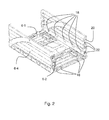
- the Fig. 2 shows the container 2 in the partially folded state, in which the two shorter side walls 6-1 and 6-2 are respectively folded inward and toward each other and come to rest flat on the floor 4.
- the side walls 6-1 and 6-2 are each connected via four joints or hinges 16 and the longer side walls 6-3 and 6-4 via five joints or hinges 18 to the bottom 4.
- the long side walls 6-3 and 6-4 each have lateral cheeks 20 which restrict the folding movement of the short side walls 6-1 and 6-2 outwardly in the vertical position and surround the outside thereof.
- These cheeks 20 have a plurality of receptacles 22, in which engage the formed on the short side walls 6-1 and 6-2 locking elements 8.
- the cheeks 20 of the long side walls 6-3 and 6-4 limit the folding movement of the short side walls 6-1 and 6-2 to the outside, the short side walls 6-1 and 6-2 ensure that the long side walls 6-3 and 6-4 do not fold in when opened.
- the rotational movement of the long side walls 6-3 and 6-4 outwardly is limited by a laterally upwardly extending from the bottom edge portion 22, on which the side walls 6-3 and 6-4 are stored and come into contact when the long side walls 6-3 and 6-4 are brought into the vertical position.
- the folding axis of the long side walls 6-3 and 6-4 is located higher than the folding axis of the short side walls 6-1 and 6-2 due to the laterally raised edge portion 24, so that the long side walls 6-3 and 6 -4 can be folded over the folded short side walls 6-1 and 6-2 and in the folded state of the bottom 4, the short side walls 6-1 and 6-2 and the long side walls 6-3 and 6-4 are plane-parallel one above the other.
- the container 2 according to the invention can be compactly compact when empty and requires only little storage space.
- each of the long side walls 6-3 and 6-4 of two side wall elements 26 and 28 which are pivotable about a hinge 30 to each other, wherein the side wall member 26 is rotatably connected via the joints 18 with the edge portion 24 of the bottom 4, while the side wall member 28 can be pivoted in the plane of the side wall 6-3 and 6-4 by 180 ° to the other side.
- the short side wall 6-2 is respectively connected to the side wall member 26, while the short side wall 6-1 is fixedly connected to the pivotable side wall member 28.
- Um like in the Fig. 4 shown to be able to pivot the two side wall elements 28 together with the short side wall 6-1, the hinge connection between the side wall 6-1 and the bottom 4 must be solved.
- the hinges 16 of the short side wall 6-1 are therefore designed so that the short side wall 6-1, when in its unfolded vertical position, will release the side wall 6-1 and the corresponding trunnions and bushes, respectively.
- the side wall 6-1 is connected by a further locking element 32 to the bottom 4, which can be unlocked when the side wall 6-1 is to be pivoted to the other side of the container ,
- a claw can be actuated by means of a provided on the side wall 6-1 handle or lever member, which engages positively and / or frictionally engaged in a formed in the container bottom 4 slot-shaped recess.
- the side wall member 26 connected to the bottom 4 is double-walled at least in the upper edge portion region, so that the pivotable side wall member 26 is guided therein and in their respective Schwenkendpositionen immersed in the double-walled portion of the side wall member 26.
- This not only allows the possibility of pivoting the side wall elements 28 and the side wall 6-1 to full 180 °, but also increases the side guidance and the lateral stability of the pivoted part, whereby the pivots 30 are relieved.
- this construction also allows the placement of the hinges 30 below the upper edge of the side walls 6-3 and 6-4, so that the hinge can be accommodated within the space defined by the four side walls 6.
- the side wall elements 28, including the pivotable side wall 6-1 has been pivoted by 180 ° to the opposite side, the side wall 6-1 is seated plane-parallel on the opposite side wall 6-2 in a flush manner.
- Schwenkend ein overlap the two side walls 6-1 and 6-2. More specifically, the two overlap respectively above the handle opening 10 portions of the side walls 6-1 and 6-2. These are designed so that the pivotable side wall 6-1 engages behind the corresponding portion of the side wall 6-2.
- the complementary design of these edge sections is in the Fig. 2 recognizable.
- the upper portion of the side wall 6-1 is stepped to be seated on the corresponding portion of the side wall 6-2.
- the double-walled upper portion of the sidewall member 26 is inwardly open at the transition to the cheek 20 to receive the corresponding upper portion of the cheek 20 of the sidewall member 28.
- the pivotable side wall elements 28 have a widened portion 34, which can additionally serve as a stop for both end positions.
- an upper edge 36 of the portion 34 in the pivoted position comes into contact with an upper edge of the side member 26 and a lower edge of the portion 34 into abutment with the upper edge 38 of the side wall member 26 when the side wall elements 28 and the side wall 6 1 again in the starting position.
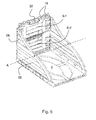
- the upper edge portion 38 of the side wall member 26 and the lower edge portion 40 of the side wall member 28 are arcuately formed around the To minimize the surface of the side wall element 28 to be pivoted, without losing much strength. It is also achieved that the products that are closer to the side of the side wall 6-1 still provide enough lateral support so as not to run the risk that they fall laterally out of the container. In addition, in particular from the Fig. 5 to see that the entire container 2 is constructed in a lightweight material construction and both the bottom 4 and the side walls 6 have stiffening geometries.
- FIGS. 6 to 8 show schematically a container 102 according to a second embodiment, which has been omitted for convenience only some of the details previously received.
- This embodiment differs from the first embodiment in that the side wall 106-3 and 106-4 respectively has another pivotable side wall member 129 on the other side of the pivot point 130, with which the other side wall 106-2, which is also pivotable , can pivot in the direction of the pivotable side wall 106-1.
- the container can be optionally opened on the side wall 106-1 side or on the side wall 106-2 side.
- the pivotable sidewall member 128 rests only on the upper edge 138 of the other pivotable sidewall member 129 and on the other of the opposite sidewall 106-2 and vice versa.
- the container 102 according to the second embodiment is the same in function and advantages as in the first embodiment.
- the Fig. 8 shows an attached on the inside of the pivotable side wall 106-1 advertising sign 142, which represents the products offered in the container 2 for sale and their price. Since the side wall 106-1 and the advertising sign 142 are located above the side wall 106-2, the advertising sign 142 is still visible from the front even if the container 102 is completely filled with products up to the upper edge 138 (immediately below the advertising sign 142 is) is filled. Thus, the retailer with the container 2 shown here save not only storage shelves and compartments, but also appropriate signage measures for product labeling.
- the billboard 142 can be removed, the side wall 106-1 swung back and all four side walls 106 folded one after another and the container 102 cleared to the side.
- the container 102 of identical design can then be restored to its presentation position by pivoting the side wall 106-1 to the opposite side, and the previously removed advertising sign 142 can be placed again.
- a corresponding holding device (not shown) may be provided.
- the goods containers are already provided with appropriate signage at their delivery.
- the signboard 142 may also be left on the outside of the hinged sidewall 106-1 upon delivery of the container 102. be visible in the normal state from the outside, be attached, if necessary, to a corresponding holder, and placed only before or after the pivoting of the side wall 106-1 on the inside of the side wall 106-1. This ensures that the advertising sign 141 can be visibly placed in the normal unfolded position as well as in the presentation position with pivoted side wall 106-1 for the customer.
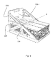
- Fig. 9 shows a container 202 according to the invention according to a third embodiment, which is in the unfolded position, ie in the presentation position and is filled with a variety of goods or general cargo.
- a pivotable side wall 206-1 has been pivoted to the opposite side wall 206-2 and rests on this.
- the longitudinal sides have openings.
- a pivotable side wall member 228 of the side wall 206-3 and 206-4 is not bent, but designed to be rectilinear.
- This embodiment also differs from the first embodiment in that the side wall 206-3 or 206-4 has another pivotable side wall element 229 on the other side of the pivot point 230, with which the other side wall 206-2, the is also designed to pivot, can pivot in the direction of the pivotable side wall 206-1.
- the container can be optionally opened on the side wall 106-1 side or on the side wall 206-2 side.
- the pivotable side wall element 228 or 229 rests on the upper edge 138 of the other pivotable side wall element 129 or 128.
- the container 202 according to the second embodiment corresponds in function and advantages to that of the first and second embodiments.
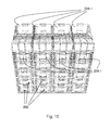
- Fig. 10 shows stacked and closely spaced containers 202, with six containers 202 stacked on top of each other and only the uppermost container 202 is in the presentation position. If this is empty, it can be removed. In this case, the side wall 206-1 pivoted backward is pivoted forward again and then all side walls 206 are folded inwards and the container is cleared away. Subsequently, underneath revealed container is brought into its presentation position by the pivotable side wall 206-1 is pivoted to the rear.
- only the short side walls are made pivotable.
- the lengths of side walls or all side walls can be made pivotable. This makes it even more flexible with regard to the possibility of positioning the container.
- the pivotable side wall is pivoted by means of side wall elements which are in fact part of the side wall.
- the side walls can be provided with an additional pivot arm or - mechanism which is guided inside or outside the side wall and is connected for the purpose of pivoting with the pivotable side wall.
- the side wall resilient elements or clamping elements or frictional connection elements can be held in connection with the ground.
- the folding mechanism for opening and closing the side walls can be made in accordance with other solutions known from the prior art, provided that these solutions do not hinder the optional release of the pivotable side wall from the ground.
Landscapes
- Engineering & Computer Science (AREA)
- Mechanical Engineering (AREA)
- Rigid Containers With Two Or More Constituent Elements (AREA)
Applications Claiming Priority (1)
| Application Number | Priority Date | Filing Date | Title |
|---|---|---|---|
| DE102011055019.4A DE102011055019B4 (de) | 2011-11-03 | 2011-11-03 | Transport- und Präsentationsbehälter |
Publications (2)
| Publication Number | Publication Date |
|---|---|
| EP2589543A1 true EP2589543A1 (fr) | 2013-05-08 |
| EP2589543B1 EP2589543B1 (fr) | 2015-07-08 |
Family
ID=46614295
Family Applications (1)
| Application Number | Title | Priority Date | Filing Date |
|---|---|---|---|
| EP12176521.8A Not-in-force EP2589543B1 (fr) | 2011-11-03 | 2012-07-16 | Récipient de transport et de présentation |
Country Status (2)
| Country | Link |
|---|---|
| EP (1) | EP2589543B1 (fr) |
| DE (1) | DE102011055019B4 (fr) |
Cited By (2)
| Publication number | Priority date | Publication date | Assignee | Title |
|---|---|---|---|---|
| EP3342729A1 (fr) * | 2017-01-02 | 2018-07-04 | Schoeller Allibert GmbH | Caisse de présentation de bouteilles |
| IT201700012755A1 (it) * | 2017-02-06 | 2018-08-06 | Giuseppe Conti | Contenitore scatolare perfezionato |
Citations (12)
| Publication number | Priority date | Publication date | Assignee | Title |
|---|---|---|---|---|
| GB2068338A (en) | 1980-01-31 | 1981-08-12 | Larosiere De Champfeu P De | Box for trays or cartons of eggs |
| WO1994010049A1 (fr) | 1992-10-28 | 1994-05-11 | Mauser-Werke Gmbh | Bac de transport reutilisable |
| EP0835816A2 (fr) | 1994-10-07 | 1998-04-15 | Schoeller-Plast S.A. | Récipient en forme de caisse |
| WO2000030946A1 (fr) * | 1998-11-25 | 2000-06-02 | Carrimor | Recipient demontable destine a contenir un fluide |
| GB2349139A (en) * | 1999-04-21 | 2000-10-25 | Lin Pac Mouldings | A container assembly |
| US6305566B1 (en) | 2000-04-07 | 2001-10-23 | Nucon Corporation | Container for fragile articles |
| US20040020821A1 (en) | 1999-11-20 | 2004-02-05 | Rehrig Pacific Company | Collapsible merchandising container |
| US20080142530A1 (en) | 2006-12-13 | 2008-06-19 | Meers Ryan C | Crate with collapsible wall |
| GB2449757A (en) | 2007-05-30 | 2008-12-03 | Rehrig Pacific Co | Knockdown collapsible container |
| US20100147840A1 (en) | 2008-12-17 | 2010-06-17 | Fred Dowd | Reusable, Combined Multi-Part Product Shipping Box and Display Tray |
| WO2011048259A1 (fr) | 2009-10-19 | 2011-04-28 | K. Hartwall Oy Ab | Caisse repliable pour le transport et la présentation de pièces, et procédé de fourniture et de promotion de produits |
| WO2011131301A1 (fr) * | 2010-04-20 | 2011-10-27 | Schoeller Arca Systems Gmbh | Récipient avec fonction d'affichage |
Family Cites Families (6)
| Publication number | Priority date | Publication date | Assignee | Title |
|---|---|---|---|---|
| US1651284A (en) * | 1926-03-06 | 1927-11-29 | Leiberman Morris | Collapsible box |
| US3326361A (en) * | 1964-09-21 | 1967-06-20 | Comly Gillam Carton Corp | Display containers |
| FR2196583A5 (fr) * | 1972-08-21 | 1974-03-15 | Cipel | |
| US5467885A (en) * | 1993-11-29 | 1995-11-21 | Blinstrub; Robert M. | Collapsible material handling container |
| US6330968B1 (en) * | 1996-10-15 | 2001-12-18 | Unibind (Cyprus) Limited | File folder with connecting side pieces |
| US6540134B1 (en) * | 1999-10-18 | 2003-04-01 | Joseph A. Rasche | Parcel box |
-
2011
- 2011-11-03 DE DE102011055019.4A patent/DE102011055019B4/de not_active Expired - Fee Related
-
2012
- 2012-07-16 EP EP12176521.8A patent/EP2589543B1/fr not_active Not-in-force
Patent Citations (12)
| Publication number | Priority date | Publication date | Assignee | Title |
|---|---|---|---|---|
| GB2068338A (en) | 1980-01-31 | 1981-08-12 | Larosiere De Champfeu P De | Box for trays or cartons of eggs |
| WO1994010049A1 (fr) | 1992-10-28 | 1994-05-11 | Mauser-Werke Gmbh | Bac de transport reutilisable |
| EP0835816A2 (fr) | 1994-10-07 | 1998-04-15 | Schoeller-Plast S.A. | Récipient en forme de caisse |
| WO2000030946A1 (fr) * | 1998-11-25 | 2000-06-02 | Carrimor | Recipient demontable destine a contenir un fluide |
| GB2349139A (en) * | 1999-04-21 | 2000-10-25 | Lin Pac Mouldings | A container assembly |
| US20040020821A1 (en) | 1999-11-20 | 2004-02-05 | Rehrig Pacific Company | Collapsible merchandising container |
| US6305566B1 (en) | 2000-04-07 | 2001-10-23 | Nucon Corporation | Container for fragile articles |
| US20080142530A1 (en) | 2006-12-13 | 2008-06-19 | Meers Ryan C | Crate with collapsible wall |
| GB2449757A (en) | 2007-05-30 | 2008-12-03 | Rehrig Pacific Co | Knockdown collapsible container |
| US20100147840A1 (en) | 2008-12-17 | 2010-06-17 | Fred Dowd | Reusable, Combined Multi-Part Product Shipping Box and Display Tray |
| WO2011048259A1 (fr) | 2009-10-19 | 2011-04-28 | K. Hartwall Oy Ab | Caisse repliable pour le transport et la présentation de pièces, et procédé de fourniture et de promotion de produits |
| WO2011131301A1 (fr) * | 2010-04-20 | 2011-10-27 | Schoeller Arca Systems Gmbh | Récipient avec fonction d'affichage |
Cited By (2)
| Publication number | Priority date | Publication date | Assignee | Title |
|---|---|---|---|---|
| EP3342729A1 (fr) * | 2017-01-02 | 2018-07-04 | Schoeller Allibert GmbH | Caisse de présentation de bouteilles |
| IT201700012755A1 (it) * | 2017-02-06 | 2018-08-06 | Giuseppe Conti | Contenitore scatolare perfezionato |
Also Published As
| Publication number | Publication date |
|---|---|
| DE102011055019A1 (de) | 2013-05-08 |
| DE102011055019B4 (de) | 2020-07-30 |
| EP2589543B1 (fr) | 2015-07-08 |
Similar Documents
| Publication | Publication Date | Title |
|---|---|---|
| DE69415496T2 (de) | Einkaufswagen für Grossmärkte oder dergleichen | |
| DE2501640A1 (de) | Mehrere verpackungskarten enthaltende packung und verfahren zum bezeichnen der verpackungskarten | |
| EP2562094A1 (fr) | Rehausse pour récipient de transport | |
| EP1772389B1 (fr) | Support pour charges de grandes dimensions | |
| EP2589543B1 (fr) | Récipient de transport et de présentation | |
| EP1160170B1 (fr) | Récipient de transport | |
| DE3216941A1 (de) | Verfahren zur erleichterung der handhabung und des transports von gegenstaenden in einkaufswagen, aufbewarungsmittel und einkaufswagen zur durchfuehrung des verfahrens | |
| EP0665803B1 (fr) | Bac de transport reutilisable | |
| DE19825768A1 (de) | Wiederverschließbarer Spender | |
| DE4230274C2 (de) | Behälter für den Transport oder die Einlagerung von Stückgut | |
| EP0639506B1 (fr) | Récipient de transport | |
| EP0610489B1 (fr) | Recipient de transport reutilisable | |
| DE897225C (de) | Fahrbarer, zusammenlegbarer Behaelter | |
| EP3342729B1 (fr) | Caisse de présentation de bouteilles | |
| DE202021101074U1 (de) | Displaysockel-Viertelpalettenbefestigung | |
| WO2007042249A1 (fr) | Support pour bouteilles et récipients similaires | |
| EP3354167B1 (fr) | Base de présentation pourvu de compartiment à marchandises dans la base | |
| DE202010002985U1 (de) | Universal Gartenwagen | |
| DE20008279U1 (de) | Transport- und Präsentationsbehälter | |
| DE3887584T2 (de) | Behältnisse, insbesondere Karteibehältnisse. | |
| DE2739291A1 (de) | Transportkarren oder -wagen | |
| DE60217960T2 (de) | Nachfüllvorrichtung für einen warenbehälter | |
| DE202024106869U1 (de) | Cover für einen Warenaufsteller | |
| DE102009049933A1 (de) | Vorrichtung zum Transport von Gegenständen | |
| WO2022028983A1 (fr) | Chariot à bras à axe unique pliable et recyclable |
Legal Events
| Date | Code | Title | Description |
|---|---|---|---|
| PUAI | Public reference made under article 153(3) epc to a published international application that has entered the european phase |
Free format text: ORIGINAL CODE: 0009012 |
|
| AK | Designated contracting states |
Kind code of ref document: A1 Designated state(s): AL AT BE BG CH CY CZ DE DK EE ES FI FR GB GR HR HU IE IS IT LI LT LU LV MC MK MT NL NO PL PT RO RS SE SI SK SM TR |
|
| AX | Request for extension of the european patent |
Extension state: BA ME |
|
| 17P | Request for examination filed |
Effective date: 20130531 |
|
| RBV | Designated contracting states (corrected) |
Designated state(s): AL AT BE BG CH CY CZ DE DK EE ES FI FR GB GR HR HU IE IS IT LI LT LU LV MC MK MT NL NO PL PT RO RS SE SI SK SM TR |
|
| 17Q | First examination report despatched |
Effective date: 20140430 |
|
| RAP1 | Party data changed (applicant data changed or rights of an application transferred) |
Owner name: SCHOELLER ALLIBERT GMBH |
|
| GRAP | Despatch of communication of intention to grant a patent |
Free format text: ORIGINAL CODE: EPIDOSNIGR1 |
|
| INTG | Intention to grant announced |
Effective date: 20150115 |
|
| GRAS | Grant fee paid |
Free format text: ORIGINAL CODE: EPIDOSNIGR3 |
|
| GRAA | (expected) grant |
Free format text: ORIGINAL CODE: 0009210 |
|
| AK | Designated contracting states |
Kind code of ref document: B1 Designated state(s): AL AT BE BG CH CY CZ DE DK EE ES FI FR GB GR HR HU IE IS IT LI LT LU LV MC MK MT NL NO PL PT RO RS SE SI SK SM TR |
|
| REG | Reference to a national code |
Ref country code: GB Ref legal event code: FG4D Free format text: NOT ENGLISH |
|
| REG | Reference to a national code |
Ref country code: AT Ref legal event code: REF Ref document number: 735206 Country of ref document: AT Kind code of ref document: T Effective date: 20150715 Ref country code: CH Ref legal event code: EP |
|
| REG | Reference to a national code |
Ref country code: IE Ref legal event code: FG4D Free format text: LANGUAGE OF EP DOCUMENT: GERMAN |
|
| REG | Reference to a national code |
Ref country code: DE Ref legal event code: R096 Ref document number: 502012003673 Country of ref document: DE |
|
| REG | Reference to a national code |
Ref country code: NL Ref legal event code: MP Effective date: 20150708 |
|
| REG | Reference to a national code |
Ref country code: LT Ref legal event code: MG4D |
|
| PG25 | Lapsed in a contracting state [announced via postgrant information from national office to epo] |
Ref country code: NO Free format text: LAPSE BECAUSE OF FAILURE TO SUBMIT A TRANSLATION OF THE DESCRIPTION OR TO PAY THE FEE WITHIN THE PRESCRIBED TIME-LIMIT Effective date: 20151008 Ref country code: LT Free format text: LAPSE BECAUSE OF FAILURE TO SUBMIT A TRANSLATION OF THE DESCRIPTION OR TO PAY THE FEE WITHIN THE PRESCRIBED TIME-LIMIT Effective date: 20150708 Ref country code: GR Free format text: LAPSE BECAUSE OF FAILURE TO SUBMIT A TRANSLATION OF THE DESCRIPTION OR TO PAY THE FEE WITHIN THE PRESCRIBED TIME-LIMIT Effective date: 20151009 Ref country code: LV Free format text: LAPSE BECAUSE OF FAILURE TO SUBMIT A TRANSLATION OF THE DESCRIPTION OR TO PAY THE FEE WITHIN THE PRESCRIBED TIME-LIMIT Effective date: 20150708 Ref country code: FI Free format text: LAPSE BECAUSE OF FAILURE TO SUBMIT A TRANSLATION OF THE DESCRIPTION OR TO PAY THE FEE WITHIN THE PRESCRIBED TIME-LIMIT Effective date: 20150708 |
|
| PG25 | Lapsed in a contracting state [announced via postgrant information from national office to epo] |
Ref country code: SE Free format text: LAPSE BECAUSE OF FAILURE TO SUBMIT A TRANSLATION OF THE DESCRIPTION OR TO PAY THE FEE WITHIN THE PRESCRIBED TIME-LIMIT Effective date: 20150708 Ref country code: HR Free format text: LAPSE BECAUSE OF FAILURE TO SUBMIT A TRANSLATION OF THE DESCRIPTION OR TO PAY THE FEE WITHIN THE PRESCRIBED TIME-LIMIT Effective date: 20150708 Ref country code: IS Free format text: LAPSE BECAUSE OF FAILURE TO SUBMIT A TRANSLATION OF THE DESCRIPTION OR TO PAY THE FEE WITHIN THE PRESCRIBED TIME-LIMIT Effective date: 20151108 Ref country code: ES Free format text: LAPSE BECAUSE OF FAILURE TO SUBMIT A TRANSLATION OF THE DESCRIPTION OR TO PAY THE FEE WITHIN THE PRESCRIBED TIME-LIMIT Effective date: 20150708 Ref country code: RS Free format text: LAPSE BECAUSE OF FAILURE TO SUBMIT A TRANSLATION OF THE DESCRIPTION OR TO PAY THE FEE WITHIN THE PRESCRIBED TIME-LIMIT Effective date: 20150708 Ref country code: PL Free format text: LAPSE BECAUSE OF FAILURE TO SUBMIT A TRANSLATION OF THE DESCRIPTION OR TO PAY THE FEE WITHIN THE PRESCRIBED TIME-LIMIT Effective date: 20150708 Ref country code: PT Free format text: LAPSE BECAUSE OF FAILURE TO SUBMIT A TRANSLATION OF THE DESCRIPTION OR TO PAY THE FEE WITHIN THE PRESCRIBED TIME-LIMIT Effective date: 20151109 |
|
| REG | Reference to a national code |
Ref country code: CH Ref legal event code: PL |
|
| REG | Reference to a national code |
Ref country code: DE Ref legal event code: R097 Ref document number: 502012003673 Country of ref document: DE |
|
| REG | Reference to a national code |
Ref country code: IE Ref legal event code: MM4A |
|
| PG25 | Lapsed in a contracting state [announced via postgrant information from national office to epo] |
Ref country code: IT Free format text: LAPSE BECAUSE OF FAILURE TO SUBMIT A TRANSLATION OF THE DESCRIPTION OR TO PAY THE FEE WITHIN THE PRESCRIBED TIME-LIMIT Effective date: 20150708 Ref country code: MC Free format text: LAPSE BECAUSE OF FAILURE TO SUBMIT A TRANSLATION OF THE DESCRIPTION OR TO PAY THE FEE WITHIN THE PRESCRIBED TIME-LIMIT Effective date: 20150708 Ref country code: DK Free format text: LAPSE BECAUSE OF FAILURE TO SUBMIT A TRANSLATION OF THE DESCRIPTION OR TO PAY THE FEE WITHIN THE PRESCRIBED TIME-LIMIT Effective date: 20150708 Ref country code: CZ Free format text: LAPSE BECAUSE OF FAILURE TO SUBMIT A TRANSLATION OF THE DESCRIPTION OR TO PAY THE FEE WITHIN THE PRESCRIBED TIME-LIMIT Effective date: 20150708 Ref country code: CH Free format text: LAPSE BECAUSE OF NON-PAYMENT OF DUE FEES Effective date: 20150731 Ref country code: LI Free format text: LAPSE BECAUSE OF NON-PAYMENT OF DUE FEES Effective date: 20150731 Ref country code: SK Free format text: LAPSE BECAUSE OF FAILURE TO SUBMIT A TRANSLATION OF THE DESCRIPTION OR TO PAY THE FEE WITHIN THE PRESCRIBED TIME-LIMIT Effective date: 20150708 Ref country code: EE Free format text: LAPSE BECAUSE OF FAILURE TO SUBMIT A TRANSLATION OF THE DESCRIPTION OR TO PAY THE FEE WITHIN THE PRESCRIBED TIME-LIMIT Effective date: 20150708 |
|
| PLBE | No opposition filed within time limit |
Free format text: ORIGINAL CODE: 0009261 |
|
| STAA | Information on the status of an ep patent application or granted ep patent |
Free format text: STATUS: NO OPPOSITION FILED WITHIN TIME LIMIT |
|
| PG25 | Lapsed in a contracting state [announced via postgrant information from national office to epo] |
Ref country code: RO Free format text: LAPSE BECAUSE OF FAILURE TO SUBMIT A TRANSLATION OF THE DESCRIPTION OR TO PAY THE FEE WITHIN THE PRESCRIBED TIME-LIMIT Effective date: 20150708 |
|
| 26N | No opposition filed |
Effective date: 20160411 |
|
| REG | Reference to a national code |
Ref country code: FR Ref legal event code: PLFP Year of fee payment: 5 |
|
| PG25 | Lapsed in a contracting state [announced via postgrant information from national office to epo] |
Ref country code: IE Free format text: LAPSE BECAUSE OF NON-PAYMENT OF DUE FEES Effective date: 20150716 |
|
| PG25 | Lapsed in a contracting state [announced via postgrant information from national office to epo] |
Ref country code: SI Free format text: LAPSE BECAUSE OF FAILURE TO SUBMIT A TRANSLATION OF THE DESCRIPTION OR TO PAY THE FEE WITHIN THE PRESCRIBED TIME-LIMIT Effective date: 20150708 |
|
| PG25 | Lapsed in a contracting state [announced via postgrant information from national office to epo] |
Ref country code: MT Free format text: LAPSE BECAUSE OF FAILURE TO SUBMIT A TRANSLATION OF THE DESCRIPTION OR TO PAY THE FEE WITHIN THE PRESCRIBED TIME-LIMIT Effective date: 20150708 |
|
| PG25 | Lapsed in a contracting state [announced via postgrant information from national office to epo] |
Ref country code: HU Free format text: LAPSE BECAUSE OF FAILURE TO SUBMIT A TRANSLATION OF THE DESCRIPTION OR TO PAY THE FEE WITHIN THE PRESCRIBED TIME-LIMIT; INVALID AB INITIO Effective date: 20120716 Ref country code: BG Free format text: LAPSE BECAUSE OF FAILURE TO SUBMIT A TRANSLATION OF THE DESCRIPTION OR TO PAY THE FEE WITHIN THE PRESCRIBED TIME-LIMIT Effective date: 20150708 Ref country code: SM Free format text: LAPSE BECAUSE OF FAILURE TO SUBMIT A TRANSLATION OF THE DESCRIPTION OR TO PAY THE FEE WITHIN THE PRESCRIBED TIME-LIMIT Effective date: 20150708 |
|
| PG25 | Lapsed in a contracting state [announced via postgrant information from national office to epo] |
Ref country code: NL Free format text: LAPSE BECAUSE OF FAILURE TO SUBMIT A TRANSLATION OF THE DESCRIPTION OR TO PAY THE FEE WITHIN THE PRESCRIBED TIME-LIMIT Effective date: 20150708 Ref country code: CY Free format text: LAPSE BECAUSE OF FAILURE TO SUBMIT A TRANSLATION OF THE DESCRIPTION OR TO PAY THE FEE WITHIN THE PRESCRIBED TIME-LIMIT Effective date: 20150708 |
|
| REG | Reference to a national code |
Ref country code: FR Ref legal event code: PLFP Year of fee payment: 6 |
|
| PG25 | Lapsed in a contracting state [announced via postgrant information from national office to epo] |
Ref country code: BE Free format text: LAPSE BECAUSE OF NON-PAYMENT OF DUE FEES Effective date: 20150731 |
|
| PG25 | Lapsed in a contracting state [announced via postgrant information from national office to epo] |
Ref country code: TR Free format text: LAPSE BECAUSE OF FAILURE TO SUBMIT A TRANSLATION OF THE DESCRIPTION OR TO PAY THE FEE WITHIN THE PRESCRIBED TIME-LIMIT Effective date: 20150708 |
|
| PG25 | Lapsed in a contracting state [announced via postgrant information from national office to epo] |
Ref country code: LU Free format text: LAPSE BECAUSE OF NON-PAYMENT OF DUE FEES Effective date: 20150716 |
|
| PG25 | Lapsed in a contracting state [announced via postgrant information from national office to epo] |
Ref country code: MK Free format text: LAPSE BECAUSE OF FAILURE TO SUBMIT A TRANSLATION OF THE DESCRIPTION OR TO PAY THE FEE WITHIN THE PRESCRIBED TIME-LIMIT Effective date: 20150708 |
|
| REG | Reference to a national code |
Ref country code: FR Ref legal event code: PLFP Year of fee payment: 7 |
|
| REG | Reference to a national code |
Ref country code: AT Ref legal event code: MM01 Ref document number: 735206 Country of ref document: AT Kind code of ref document: T Effective date: 20170716 |
|
| PG25 | Lapsed in a contracting state [announced via postgrant information from national office to epo] |
Ref country code: AL Free format text: LAPSE BECAUSE OF FAILURE TO SUBMIT A TRANSLATION OF THE DESCRIPTION OR TO PAY THE FEE WITHIN THE PRESCRIBED TIME-LIMIT Effective date: 20150708 |
|
| PG25 | Lapsed in a contracting state [announced via postgrant information from national office to epo] |
Ref country code: AT Free format text: LAPSE BECAUSE OF NON-PAYMENT OF DUE FEES Effective date: 20170716 |
|
| PGFP | Annual fee paid to national office [announced via postgrant information from national office to epo] |
Ref country code: DE Payment date: 20240620 Year of fee payment: 13 |
|
| PGFP | Annual fee paid to national office [announced via postgrant information from national office to epo] |
Ref country code: GB Payment date: 20240723 Year of fee payment: 13 |
|
| PGFP | Annual fee paid to national office [announced via postgrant information from national office to epo] |
Ref country code: FR Payment date: 20240724 Year of fee payment: 13 |
|
| REG | Reference to a national code |
Ref country code: DE Ref legal event code: R119 Ref document number: 502012003673 Country of ref document: DE |
|
| GBPC | Gb: european patent ceased through non-payment of renewal fee |
Effective date: 20250716 |
|
| PG25 | Lapsed in a contracting state [announced via postgrant information from national office to epo] |
Ref country code: GB Free format text: LAPSE BECAUSE OF NON-PAYMENT OF DUE FEES Effective date: 20250716 |
|
| PG25 | Lapsed in a contracting state [announced via postgrant information from national office to epo] |
Ref country code: DE Free format text: LAPSE BECAUSE OF NON-PAYMENT OF DUE FEES Effective date: 20260203 |
|
| PG25 | Lapsed in a contracting state [announced via postgrant information from national office to epo] |
Ref country code: FR Free format text: LAPSE BECAUSE OF NON-PAYMENT OF DUE FEES Effective date: 20250731 |