EP2589703A2 - Caisson de drainage de rail avec rails d'ornière de guidage dotés d'un contrerail et d'une ornière de guidage - Google Patents
Caisson de drainage de rail avec rails d'ornière de guidage dotés d'un contrerail et d'une ornière de guidage Download PDFInfo
- Publication number
- EP2589703A2 EP2589703A2 EP12191362.8A EP12191362A EP2589703A2 EP 2589703 A2 EP2589703 A2 EP 2589703A2 EP 12191362 A EP12191362 A EP 12191362A EP 2589703 A2 EP2589703 A2 EP 2589703A2
- Authority
- EP
- European Patent Office
- Prior art keywords
- box
- rail
- drainage
- guide rail
- drainage box
- Prior art date
- Legal status (The legal status is an assumption and is not a legal conclusion. Google has not performed a legal analysis and makes no representation as to the accuracy of the status listed.)
- Withdrawn
Links
- 239000000463 material Substances 0.000 claims abstract description 9
- 239000002184 metal Substances 0.000 claims description 3
- 229910052500 inorganic mineral Inorganic materials 0.000 claims description 2
- 239000011707 mineral Substances 0.000 claims description 2
- 238000013459 approach Methods 0.000 abstract 1
- 229910010272 inorganic material Inorganic materials 0.000 abstract 1
- 239000011147 inorganic material Substances 0.000 abstract 1
- 238000003466 welding Methods 0.000 description 5
- XLYOFNOQVPJJNP-UHFFFAOYSA-N water Substances O XLYOFNOQVPJJNP-UHFFFAOYSA-N 0.000 description 4
- 229910000831 Steel Inorganic materials 0.000 description 3
- 238000010276 construction Methods 0.000 description 3
- 239000010959 steel Substances 0.000 description 3
- 238000005553 drilling Methods 0.000 description 2
- 238000011010 flushing procedure Methods 0.000 description 2
- 239000007769 metal material Substances 0.000 description 2
- 230000001419 dependent effect Effects 0.000 description 1
- 238000005516 engineering process Methods 0.000 description 1
- 238000012423 maintenance Methods 0.000 description 1
- 238000000034 method Methods 0.000 description 1
- 230000002028 premature Effects 0.000 description 1
Images


Classifications
-
- E—FIXED CONSTRUCTIONS
- E01—CONSTRUCTION OF ROADS, RAILWAYS, OR BRIDGES
- E01B—PERMANENT WAY; PERMANENT-WAY TOOLS; MACHINES FOR MAKING RAILWAYS OF ALL KINDS
- E01B21/00—Track superstructure adapted for tramways in paved streets
- E01B21/02—Special supporting means; Draining of rails
Definitions
- the invention relates to a Schienenent camess mecanicskasten for rafter rails with a guide rail and a track groove, consisting of a box body with a Rohrabpound, the attachment to the purrilleschiene serving components and a detachably attachable to the box body box cover.
- a rail drainage box for ruts rails which serves as an inlet piece for drainage of a railway or track system.
- the flap chamber of the purrille rail facing side of the drainage box is open. Through an opening in the bottom of the rafter rail water can drain through the box opening into a drainage. This opening is variable, so that it rests in all Purrillenschienenprofilen to the rolled track groove
- the drainage box is arranged as a complete element next to the rail in the chamber, wherein no components engage in the relevant for the tracking area of the rail.
- the drainage boxes are usually designed either as a welded or as a cast construction. Constructions made of concrete are also known, mostly in combination with specially shaped fittings on the drainage slot.
- the invention is therefore an object of the invention to provide a Schienenentskysstationskasten for rafter rails with a guide rail and a track groove, in which these disadvantages are eliminated.
- the invention provides that in the guide rail on a defined, predetermined length a laterally arranged, the groove bottom of the track groove comprehensive cutout is introduced for the drainage box, that the box lid on the drainage box into the region of the cutout of the guide rail and reaches up to the track groove and that the ridge directed towards the front edge of the box cover is designed as a tracking guide of the guide rail in the region of the cutout.
- the rail drainage box according to the invention thus provides to carry out the cutout or drainage slot wider or larger than hitherto usual and with better quality of its side surfaces.
- the cutout is made so accessible that using a standard cutting and / or grinding wheel the parting surfaces are subsequently machined and their roughness is thus significantly reduced, whereby the known in the prior art, crucial starting point for the functional failure is reduced.
- the rafter rail 1 comprises according to Fig. 1 a rail head 2 for guiding the wheel rim of a track wheel, not shown, a track groove 3 with an externally mounted guide rail 4 for guiding the flange of the track wheel, not shown, a rail web 5 and a rail 33.
- a rail drainage box 6 of the width B ( Fig. 3 ) is in the guide rail 4 on a defined, predetermined length L ( Fig. 3 ) a laterally arranged, the groove bottom 7 of the track groove 3 comprehensive cutout 8 between two side walls 9 of the guide rail 4, whose a side wall 9 in Fig. 1 is shown.
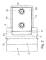
- the extending through the rail web 5 longitudinal center plane 10 of the rafter rail 1 is in Fig. 1 and Fig. 2 shown.
- the center plane 11 of the rail drainage box 6 and the longitudinal axis 12 of a longitudinal member 13 for attachment of the drainage box 6 on the rail web 5 are shown.
- the rail drainage box 6, whose width B is equal to or slightly smaller than the length L of the cutout 8 in the guide rails 4 (FIG. Fig. 3 ), comprising a box body 32 of two side walls 14, 15, a rear wall 16 and a box bottom 17, which according to Fig. 1 is inclined towards the rear wall 16 and has a Rohrabmann 18 at the lower end of the box bottom 17.
- the rail web 5 facing towards the front of the rail drainage box 6 is provided with the side rail 13 which is bolted by means of holes 19 cross, not shown components, in particular screw, with the rail web 5.
- the two side walls 14, 15, the rear wall 16, the bottom 17 with the Rohrabpound 18 and the side rail 13 are made of metallic material and are connected to each other by welding.
- supports 20, 21 are welded to the upper edges of the side and rear walls 14, 15 at a distance D from the side walls 14, 15, parallel to the rear wall 16 , provided with holes 24 and these associated welding nuts 25 flat steel beams 22, 23 are welded at a distance from each other.
- a metal box cover 26 of width b and the thickness D is used, which comes to rest on the right and left supports 20, 21.
- Fig. 1 shows, in the box cover 26 at a distance from each other and in the transverse direction of the rafter rail 1 through holes 27 are formed on the underside of washers 28 are arranged and welded to the underside of the box lid 26. Through the washers 28 engage bolts 29 through which are screwed into the weld nuts 25 by means of attacking from above on the screw heads 30, not shown tools.
- Fig. 1 As it is in particular in Fig. 1 is shown, the beveled according to the guide rail 4 leading edge 31 of the box lid 25, the guide rail 4 in the region of the cutout 8 of the rafter rail. 1
- the metallic material of the box lid 26 is made of a material having a higher wear resistance than the material of the box body 6.
- the box body 6 and the box lid 26 may also be formed of a plastic, a mineral material or metal in welded or cast version.
- the rail drainage box 6 is located in the ridge rail 1 exactly between two side surfaces 9 of the cutout 8 in the guide rail 4. Dirt and water can flow through the cutout 8 in the box body 32 of the rail drainage box 6, collected there and connected to the pipe outlet 18 drainage device the railway or track system are discharged.
- the drainage box 6 has for this reason on its underside the Rohrabpound 18 and on its upper side from the drainage box 6 removable box cover 26 to clean the drainage box 6 with flushing equipment can.
Landscapes
- Engineering & Computer Science (AREA)
- Architecture (AREA)
- Civil Engineering (AREA)
- Structural Engineering (AREA)
- Sewage (AREA)
- Operating, Guiding And Securing Of Roll- Type Closing Members (AREA)
Applications Claiming Priority (1)
| Application Number | Priority Date | Filing Date | Title |
|---|---|---|---|
| DE201120051884 DE202011051884U1 (de) | 2011-11-07 | 2011-11-07 | Schienenentwässerungskasten für Spurrillenschienen mit einer Leitschiene und einer Spurrille |
Publications (2)
| Publication Number | Publication Date |
|---|---|
| EP2589703A2 true EP2589703A2 (fr) | 2013-05-08 |
| EP2589703A3 EP2589703A3 (fr) | 2014-08-27 |
Family
ID=45372942
Family Applications (1)
| Application Number | Title | Priority Date | Filing Date |
|---|---|---|---|
| EP12191362.8A Withdrawn EP2589703A3 (fr) | 2011-11-07 | 2012-11-06 | Caisson de drainage de rail avec rails d'ornière de guidage dotés d'un contrerail et d'une ornière de guidage |
Country Status (2)
| Country | Link |
|---|---|
| EP (1) | EP2589703A3 (fr) |
| DE (1) | DE202011051884U1 (fr) |
Cited By (1)
| Publication number | Priority date | Publication date | Assignee | Title |
|---|---|---|---|---|
| DE102017111298A1 (de) | 2017-05-23 | 2018-11-29 | Dätwyler Sealing Technologies Deutschland Gmbh | Schienenanordnung für Schienenfahrzeuge mit Spurkranzrädern |
Families Citing this family (2)
| Publication number | Priority date | Publication date | Assignee | Title |
|---|---|---|---|---|
| DE102014010666A1 (de) * | 2014-07-18 | 2016-01-21 | OSC-RAILTEC GmbH | Mit einer verschließbbaren Rile ausgestattete Schiene für Straßenbahnen |
| CN111472213B (zh) * | 2020-05-08 | 2021-07-02 | 中铁十四局集团第五工程有限公司 | 提高有轨电车浅槽道岔运行速度的装置及方法 |
Citations (1)
| Publication number | Priority date | Publication date | Assignee | Title |
|---|---|---|---|---|
| DE8601339U1 (de) | 1986-01-21 | 1986-09-04 | Fa. Dieter Wolff, 8034 Germering | Schienenentwässerungskasten |
Family Cites Families (1)
| Publication number | Priority date | Publication date | Assignee | Title |
|---|---|---|---|---|
| GB191203562A (en) * | 1912-02-13 | 1912-06-06 | James Neave | Combined Permanent Way Gully and Rail Drain Box. |
-
2011
- 2011-11-07 DE DE201120051884 patent/DE202011051884U1/de not_active Expired - Lifetime
-
2012
- 2012-11-06 EP EP12191362.8A patent/EP2589703A3/fr not_active Withdrawn
Patent Citations (1)
| Publication number | Priority date | Publication date | Assignee | Title |
|---|---|---|---|---|
| DE8601339U1 (de) | 1986-01-21 | 1986-09-04 | Fa. Dieter Wolff, 8034 Germering | Schienenentwässerungskasten |
Cited By (3)
| Publication number | Priority date | Publication date | Assignee | Title |
|---|---|---|---|---|
| DE102017111298A1 (de) | 2017-05-23 | 2018-11-29 | Dätwyler Sealing Technologies Deutschland Gmbh | Schienenanordnung für Schienenfahrzeuge mit Spurkranzrädern |
| WO2018215033A2 (fr) | 2017-05-23 | 2018-11-29 | Dätwyler Sealing Technologies Deutschland Gmbh | Ensemble rail pour véhicules ferroviaires à roues à boudin |
| US11891760B2 (en) | 2017-05-23 | 2024-02-06 | Daetwyler Sealing Technologies Deutschland Gmbh | Rail assembly for rail vehicles having flanged wheels |
Also Published As
| Publication number | Publication date |
|---|---|
| EP2589703A3 (fr) | 2014-08-27 |
| DE202011051884U1 (de) | 2011-11-18 |
Similar Documents
| Publication | Publication Date | Title |
|---|---|---|
| EP0811818A1 (fr) | Plaque de grille et procédé pour sa fabrication | |
| DE9416495U1 (de) | Dachwassereinlauf | |
| DE102014006274A1 (de) | Schraubverbindung zur Befestigung eines Randsteinabweisers am Räumschild eines Schneepfluges | |
| EP2589703A2 (fr) | Caisson de drainage de rail avec rails d'ornière de guidage dotés d'un contrerail et d'une ornière de guidage | |
| EP1880968A1 (fr) | Utilisation de glissières de montage destinées à l'utilisation dans un sabot de guidage d'une installation d'ascenseur, procédé destiné à la mise en service d'une installation d'ascenseur tout comme ensemble de montage correspondant et une installation d'ascenseur correspondante | |
| EP0830480B1 (fr) | Dispositif de contre-rail pour rails a orniere | |
| DE60011387T2 (de) | Verfahren zur Reinigung von Entwässerungsrinnen | |
| DE69913948T2 (de) | Trenngitter | |
| DE4234282C2 (de) | Rinnenschuß für Kettenkratzförderer, insbesondere für den Einsatz in Bergbau-Gewinnungsbetrieben | |
| DE29914492U1 (de) | Scharnierbarer Straßenaufsatz | |
| DE2904428A1 (de) | Entwaesserungssystem fuer brueckentragwerke | |
| DE800980C (de) | Blechrahmen fuer Fahrzeuge, insbesondere Lokomotiven | |
| DE7836342U1 (de) | Wasserverteiler fuer ein zylindrisches filtersieb | |
| EP1423220A1 (fr) | Procede et dispositif permettant d'evacuer l'eau d'ecoulement retenue dans la courbure interieure d'une machine a couler des ebauches de poutrelles | |
| DE19940980A1 (de) | Vorrichtung zum Reinigen eines maschinenbreiten Ablaufzwickels in einer Papier- oder Kartonherstellungsmaschine | |
| EP3631086B1 (fr) | Ensemble rail pour véhicules ferroviaires à roues à boudin | |
| DE602004006101T2 (de) | Bahnschalter, insbesondere für U-Bahnen, Strassenbahnen und Eisenbahnschienen | |
| DE102012025114A1 (de) | Schraubverbindung für Randsteinabweiser | |
| EP2447442A2 (fr) | Elément de revêtement de sol | |
| DE202004010666U1 (de) | Vorrichtung zum Überbrücken einer Fuge eines Bauwerks | |
| EP3399102B1 (fr) | Dispositif de lame d'aiguillage doté du dispositif de réglage et procédé de fabrication d'un dispositif de lame d'aiguillage doté du dispositif de réglage, en particulier pour aiguilles de rails encastrés | |
| DE29822550U1 (de) | Element einer trommelförmigen Zerkleinerungsbahn | |
| DE29914889U1 (de) | Beschlagteil einer Holzzargenkonstruktion zum Einbau in Holzzargen, insbesondere Blockzargen | |
| EP4273320A1 (fr) | Rail doté d'une rainure de rail remplie | |
| DE202016104146U1 (de) | Nischenpoller |
Legal Events
| Date | Code | Title | Description |
|---|---|---|---|
| PUAI | Public reference made under article 153(3) epc to a published international application that has entered the european phase |
Free format text: ORIGINAL CODE: 0009012 |
|
| AK | Designated contracting states |
Kind code of ref document: A2 Designated state(s): AL AT BE BG CH CY CZ DE DK EE ES FI FR GB GR HR HU IE IS IT LI LT LU LV MC MK MT NL NO PL PT RO RS SE SI SK SM TR |
|
| AX | Request for extension of the european patent |
Extension state: BA ME |
|
| PUAL | Search report despatched |
Free format text: ORIGINAL CODE: 0009013 |
|
| AK | Designated contracting states |
Kind code of ref document: A3 Designated state(s): AL AT BE BG CH CY CZ DE DK EE ES FI FR GB GR HR HU IE IS IT LI LT LU LV MC MK MT NL NO PL PT RO RS SE SI SK SM TR |
|
| AX | Request for extension of the european patent |
Extension state: BA ME |
|
| RIC1 | Information provided on ipc code assigned before grant |
Ipc: E01B 21/02 20060101AFI20140718BHEP |
|
| 17P | Request for examination filed |
Effective date: 20150226 |
|
| RBV | Designated contracting states (corrected) |
Designated state(s): AL AT BE BG CH CY CZ DE DK EE ES FI FR GB GR HR HU IE IS IT LI LT LU LV MC MK MT NL NO PL PT RO RS SE SI SK SM TR |
|
| STAA | Information on the status of an ep patent application or granted ep patent |
Free format text: STATUS: THE APPLICATION IS DEEMED TO BE WITHDRAWN |
|
| 18D | Application deemed to be withdrawn |
Effective date: 20160601 |