EP2589802A1 - Vorrichtung zur windkrafterzeugung - Google Patents
Vorrichtung zur windkrafterzeugung Download PDFInfo
- Publication number
- EP2589802A1 EP2589802A1 EP11800537.0A EP11800537A EP2589802A1 EP 2589802 A1 EP2589802 A1 EP 2589802A1 EP 11800537 A EP11800537 A EP 11800537A EP 2589802 A1 EP2589802 A1 EP 2589802A1
- Authority
- EP
- European Patent Office
- Prior art keywords
- nacelle
- wind power
- power generator
- wall
- heat
- Prior art date
- Legal status (The legal status is an assumption and is not a legal conclusion. Google has not performed a legal analysis and makes no representation as to the accuracy of the status listed.)
- Withdrawn
Links
Images


Classifications
-
- F—MECHANICAL ENGINEERING; LIGHTING; HEATING; WEAPONS; BLASTING
- F03—MACHINES OR ENGINES FOR LIQUIDS; WIND, SPRING, OR WEIGHT MOTORS; PRODUCING MECHANICAL POWER OR A REACTIVE PROPULSIVE THRUST, NOT OTHERWISE PROVIDED FOR
- F03D—WIND MOTORS
- F03D80/00—Details, components or accessories not provided for in groups F03D1/00 - F03D17/00
-
- F—MECHANICAL ENGINEERING; LIGHTING; HEATING; WEAPONS; BLASTING
- F03—MACHINES OR ENGINES FOR LIQUIDS; WIND, SPRING, OR WEIGHT MOTORS; PRODUCING MECHANICAL POWER OR A REACTIVE PROPULSIVE THRUST, NOT OTHERWISE PROVIDED FOR
- F03D—WIND MOTORS
- F03D80/00—Details, components or accessories not provided for in groups F03D1/00 - F03D17/00
- F03D80/60—Cooling or heating of wind motors
-
- F—MECHANICAL ENGINEERING; LIGHTING; HEATING; WEAPONS; BLASTING
- F05—INDEXING SCHEMES RELATING TO ENGINES OR PUMPS IN VARIOUS SUBCLASSES OF CLASSES F01-F04
- F05B—INDEXING SCHEME RELATING TO WIND, SPRING, WEIGHT, INERTIA OR LIKE MOTORS, TO MACHINES OR ENGINES FOR LIQUIDS COVERED BY SUBCLASSES F03B, F03D AND F03G
- F05B2230/00—Manufacture
- F05B2230/90—Coating; Surface treatment
-
- F—MECHANICAL ENGINEERING; LIGHTING; HEATING; WEAPONS; BLASTING
- F05—INDEXING SCHEMES RELATING TO ENGINES OR PUMPS IN VARIOUS SUBCLASSES OF CLASSES F01-F04
- F05B—INDEXING SCHEME RELATING TO WIND, SPRING, WEIGHT, INERTIA OR LIKE MOTORS, TO MACHINES OR ENGINES FOR LIQUIDS COVERED BY SUBCLASSES F03B, F03D AND F03G
- F05B2240/00—Components
- F05B2240/10—Stators
- F05B2240/14—Casings, housings, nacelles, gondels or the like, protecting or supporting assemblies there within
-
- F—MECHANICAL ENGINEERING; LIGHTING; HEATING; WEAPONS; BLASTING
- F05—INDEXING SCHEMES RELATING TO ENGINES OR PUMPS IN VARIOUS SUBCLASSES OF CLASSES F01-F04
- F05B—INDEXING SCHEME RELATING TO WIND, SPRING, WEIGHT, INERTIA OR LIKE MOTORS, TO MACHINES OR ENGINES FOR LIQUIDS COVERED BY SUBCLASSES F03B, F03D AND F03G
- F05B2260/00—Function
- F05B2260/60—Fluid transfer
- F05B2260/64—Aeration, ventilation, dehumidification or moisture removal of closed spaces
-
- Y—GENERAL TAGGING OF NEW TECHNOLOGICAL DEVELOPMENTS; GENERAL TAGGING OF CROSS-SECTIONAL TECHNOLOGIES SPANNING OVER SEVERAL SECTIONS OF THE IPC; TECHNICAL SUBJECTS COVERED BY FORMER USPC CROSS-REFERENCE ART COLLECTIONS [XRACs] AND DIGESTS
- Y02—TECHNOLOGIES OR APPLICATIONS FOR MITIGATION OR ADAPTATION AGAINST CLIMATE CHANGE
- Y02E—REDUCTION OF GREENHOUSE GAS [GHG] EMISSIONS, RELATED TO ENERGY GENERATION, TRANSMISSION OR DISTRIBUTION
- Y02E10/00—Energy generation through renewable energy sources
- Y02E10/70—Wind energy
- Y02E10/72—Wind turbines with rotation axis in wind direction
-
- Y—GENERAL TAGGING OF NEW TECHNOLOGICAL DEVELOPMENTS; GENERAL TAGGING OF CROSS-SECTIONAL TECHNOLOGIES SPANNING OVER SEVERAL SECTIONS OF THE IPC; TECHNICAL SUBJECTS COVERED BY FORMER USPC CROSS-REFERENCE ART COLLECTIONS [XRACs] AND DIGESTS
- Y02—TECHNOLOGIES OR APPLICATIONS FOR MITIGATION OR ADAPTATION AGAINST CLIMATE CHANGE
- Y02P—CLIMATE CHANGE MITIGATION TECHNOLOGIES IN THE PRODUCTION OR PROCESSING OF GOODS
- Y02P70/00—Climate change mitigation technologies in the production process for final industrial or consumer products
- Y02P70/50—Manufacturing or production processes characterised by the final manufactured product
Definitions
- the present invention relates to wind power generators that generate power by receiving wind force on wind-turbine blades and, in particular, relates to a technique for suppressing the amount of heat input to the interior of a nacelle of a wind power generator.
- a wind power generator (hereinafter referred to as “wind turbine”) is a device in which a rotor head equipped with wind-turbine blades rotates upon receiving wind force, and in which a generator driven by, for example, accelerating this rotation with a gear box generates electricity.
- the above-described rotor head is attached at an end portion of a nacelle, which is installed on top of a wind turbine tower (hereinafter referred to as “tower”) in a manner that allows yawing, and is supported so as to be rotatable about a substantially horizontal lateral rotation axis.
- a device for transmitting a mechanical rotational force received from the wind-turbine blades and a power generator are installed inside the nacelle of the wind power generator.
- the rotational-force transmitting device is provided with a main bearing and a gear box
- the power generator is provided with a generator, a transformer, an inverter, and a control panel, or is provided with a generator and a control panel.
- Such equipment in the nacelle is cooled by using outside air that is sucked in through a nacelle air inlet, performing heat exchange between the outside air and a coolant with individual heat exchangers, which are installed on each piece of equipment serving as a heat source, and supplying the coolant, whose heat has been absorbed by the outside air, to the equipment to be cooled.
- the outside air to be sucked into the nacelle is generally subjected to salt removal treatment and dust removal treatment through a filter.
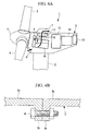
- FIG. 4A As a conventional example employing heat exchange between the outside air and the coolant, specific examples of each piece of equipment releasing heat are illustrated in Figs. 4A and 4B .
- reference sign 1 in the figure designates a wind power generator
- 2 designates a tower
- 3 designates a nacelle
- 4 designates a rotor head
- 5 designates wind-turbine blades
- 6 designates a nacelle air inlet
- 7 designates an air outlet.
- Fig. 4B is an enlarged view of relevant portions of the wall surface structure of the nacelle 3.
- the nacelle wall surface of a general nacelle structure has an outside wall structure that is formed by connecting a plurality of separated wall members 3a, which are made of fiber reinforced plastic (hereinafter referred to as "FRP"), and a structure in which flange parts 3b provided inside the nacelle are connected with bolts and nuts 8 is employed.
- FRP fiber reinforced plastic
- cooling of a main bearing 9 and a gear box 10, which constitute mechanical transmission devices is achieved by using lubricating oil, which circulates through a lubricating oil circulatory system, as the coolant for heat exchange with the outside air.
- lubricating oil which circulates through a lubricating oil circulatory system
- heat exchange between the lubricating oil and the outside air is performed in an oil cooler 11, and lubrication and cooling of frictional heat are achieved by supplying the lubricating oil that has been cooled due to the heat absorption with the outside air to rotating parts.
- antifreeze is used as the coolant for heat exchange with the outside air
- primary air is used as the coolant for heat exchange with the outside air.
- continuous cooling is achieved by supplying and circulating the antifreeze or the primary air, which have been taken into the outside air, to electrical apparatuses that are heat sources to be cooled.
- Reference sign 14 in this figure designates a transformer.
- the above-described outside air flows into the nacelle 3 through the nacelle air inlet 6 by operating a fan 15.
- This outside air flows within the nacelle 3 to exchange heat with various types of coolants, and to ventilate and cool the inside of the nacelle, and after that, the outside air flows out through the air outlet 7.
- the wall members 3a of the nacelle 3 are made of FRP generally having a wall thickness of about 100 mm, the thermal insulance of the FRP becomes dominant. Therefore, the effect of heat input from sunlight can be effectively negligible in many cases.
- PTL 1 discloses a structure having a heat-shield-coating composition, and a film thereof, having high heat-shielding properties for preventing the intrusion of thermal energy by efficiently reflecting thermal energy such as sunlight.
- an ultraviolet-reflecting coating is applied to the blade surfaces of a wind turbine for preventing birds from accidentally colliding or coming into contact with the rotating wind-turbine blades.
- the solar constant (the amount of incoming solar energy per unit area incident on the surface of the earth's atmosphere perpendicularly) is about 1370 W/m 2 , and thus, by assuming that the top and side surfaces of the nacelle form a substantially cuboid shape having a heat receiving area of 80 m 2 (nacelle height of 4 m, nacelle width of 4 m, and nacelle length of 5 m), the amount of heat input to the wall surfaces from the sun will be about 77 kW at an atmospheric transmittance of 0.7.
- the plate thickness of the wall member 3a of the above-described nacelle 3 made of FRP is reduced in order to reduce the weight, the amount of heat input to the interior of the nacelle from sunlight increases due to the reduction in thermal insulance.
- the air temperature inside the nacelle exceeds the maximum environmental temperature for the electronic equipment, which causes the lifetime of the electronic equipment to decrease.
- the input-heat resistance and heat-dissipation resistance of the wall member 3a are in an inverse relationship; however, with the current state of the art, it has been difficult to achieve a reduction in weight by reducing the plate thickness of the nacelle wall 3a, while at the same time suppressing the increase in the amount of heat input to the interior of the nacelle 3.
- the present invention has been conceived in light of the circumstances described above, and an object thereof is to provide a wind power generator that can achieve reduced weight by reducing the wall thickness of the nacelle and that suppresses the increase in the amount of heat input to the interior of the nacelle from sunlight.
- a wind power generator is a wind power generator in which driving / power-generating mechanisms linked to a rotor head to which a wind-turbine blade is attached are accommodated and installed inside a nacelle, wherein a coating of high-reflectivity paint is formed on at least part of an outer wall that receives sunlight.
- the coating of high-reflectivity paint is formed on at least part of the outer wall that receives sunlight, it is possible to reduce the input heat by selectively reflecting, with the coating of high-reflectivity paint, the near-infrared band, which contributes to heating.
- the high-reflectivity paint is paint that is made highly reflective in the near-infrared band (780 nm to 2500 nm) in comparison with general paint, by mixing hollow ceramic beads, high-reflectivity pigment etc. therein, and it is used by applying it to a film thickness of about 100 to 150 ⁇ m on a surface where reflection is desired.
- the outer wall preferably includes a nacelle outer wall, a rotor head cover, and a tower wall; if the coating of high-reflectivity paint is formed on at least part of the outer wall in this way, it is possible to reduce the heat input to the inside of these from sunlight.
- At least one of the nacelle outer wall and the rotor head cover is preferably formed of fiber-reinforced plastic, and a layer of reflective material is preferably provided on a layer of the fiber-reinforced plastic; accordingly, the separate task of painting for applying the high-reflectivity paint is not required, and it is possible to reduce the heat input by selectively reflecting the near-infrared band, which contributes to heating.
- the layer of reflecting material is preferably formed on the inner side of a gel coating layer formed as a durable clear layer; accordingly, impairment of the reflective effect due to erosion etc. can be suppressed, which extends the lifetime.
- a wind power generator is a wind power generator in which driving / power-generating mechanisms linked to a rotor head to which a wind-turbine blade is attached are accommodated and installed inside a nacelle, wherein a reflecting plate to which high-reflectivity paint is applied is attached to a nacelle outer wall that receives sunlight.
- the reflecting plate on which the high-reflectivity paint is applied is attached to the nacelle outer wall that receives sunlight, at the nacelle outer wall that receives the most sunlight, the coating of high-reflectivity paint selectively reflects the near-infrared band, which contributes to heating, and the heat input can be suppressed.
- a reflecting plate is particularly advantageous as a countermeasure against input heat from sunlight in existing wind power generators.
- the reflecting plate is preferably formed of fiber-reinforced plastic, and a layer of reflective material is preferably provided on a layer of the fiber reinforced plastic; accordingly, the separate task of painting for applying the high-reflectivity paint is not required, and the heat input can be suppressed by selectively reflecting the near-infrared band, which contributes to heating.
- the layer of reflecting material is preferably formed on the inner side of a gel coating layer formed as the durable clear layer; accordingly, impairment of the reflective effect due to erosion etc. can be suppressed, which extends the lifetime.
- the present invention realizes a reduction in the amount of heat input and an improvement in the heat dissipation properties by achieving a reduction in weight by reducing the plate thickness of the nacelle walls, while at the same time suppressing the increase in the amount of heat input to the interior of the nacelle by forming a coating of high-reflectivity paint or a sunlight-reflecting surface.
- a wind power generator 1A includes a tower 2 erected upright on a base, a nacelle 3 provided at the top of the tower 2, and a rotor head 4 provided on the nacelle 3 in such a manner as to be capable of rotating about a substantially horizontal axis.
- a plurality of (for example, three) wind-turbine blades 5 are attached to the rotor head 4 in a radiating pattern around a rotational axis thereof.
- the force of wind striking the wind-turbine blades 5 from the direction of the rotational axis of the rotor head 4 is converted into a motive force causing the rotor head 4 to rotate about its rotational axis.
- the illustrated wind power generator 1A is of a so-called upwind type in which the wind-turbine blades 5 rotate in front of the nacelle 3, the invention described below is not limited thereto and can also be applied, for example, to a downwind type.
- a main bearing 9 and a gear box 10 are provided inside the nacelle 3 as a mechanical-driving-force transmission mechanism that transmits the rotation of the rotor head 4 to a generator 13.
- an inverter control panel 12, a transformer 14 that transforms the voltage of the electrical power generated by the generator 13, and so forth are also installed inside the nacelle 3 as various kinds of electrical equipment constituting a power-generating mechanism with the generator 13.
- the wind power generator 1A is provided with driving / power-generating mechanisms linked to the rotor head 4 to which the wind turbine blades 5 are attached, which are accommodated and installed inside the nacelle 3.
- driving / power-generating mechanisms include equipment that generates heat when operating, and mechanical parts and electrical equipment whose environmental temperature is fixed.
- the nacelle 3 is a hollow member having a substantially cuboid shape in which the periphery of a nacelle base plate and frame components, which are not shown, are covered with a wall member 3a.
- the wall member 3a is, for example, a platelike member made of fiber-reinforced plastic (FRP), and this wall member 3a forms the outer wall of the nacelle 3.
- a nacelle air inlet 6 formed in the wall member 3a is provided at the bottom of the front end face of the nacelle 3 for introducing outside air into the nacelle 3 for cooling.
- a filter having the functions of removing salt and dust is mounted in this nacelle air inlet 6.
- an exhaust port 7, on which a rain guard 7a is mounted at an opening in the wall member 3a, is provided at the upper surface of the nacelle 3 for discharging the cooling outside air that has circulated inside the nacelle 3 into the atmosphere.
- the outside air that is introduced through the nacelle air inlet 6 by operating a fan 15 is released into the atmosphere from the exhaust port 7, with its temperature increased after it is used in heat exchange with coolant that cools the heat-generating equipment installed inside the nacelle 3, as explained in the Background Art.
- the arrow Ca in the figure shows an example of the main flow of outside air, and the actual flow of outside air is made to flow by circulating inside the nacelle 3 depending on the placement of heat exchangers disposed inside the nacelle 3.
- a coating 20 of high-reflectivity paint is formed on at least part of the outer wall that receives sunlight.
- the coating 20 is formed on the outer surfaces at the top (including the outer surface of the rain guard 7a) and side faces (both side faces and the rear end face) of the nacelle 3.
- the high-reflectivity paint is paint that is made highly reflective in the infrared region (780 nm to 2500 nm) compared with general paint by mixing hollow ceramic beads, high-reflectivity pigments, or the like therein. This high-reflectivity paint is used by applying it to a film thickness of approximately 100 to 150 ⁇ m to form the coating 20 on faces where it is desired to reflect sunlight.
- the reflectivity of the high-reflectivity paint is generally about 0.8 to 0.9.
- the heat-receiving area of the top and side faces of the substantially cuboid nacelle 3 is 80 m 2 (a nacelle height of 4 m, a nacelle width of 4 m, and a nacelle length of 5 m)
- the amount of heat input to the walls of the nacelle from the sun is about 77 kW.
- the heat input to the interior of the nacelle 3 can be considerably reduced from 77 kW to about 8 to 16 kW. Therefore, it is not necessary to make the wall member 3a of the nacelle 3 thick to increase the input-heat resistance.
- the thermal conductivity of the FRP used in the wall member 3a of the nacelle 3 is assumed to be 0.3 W/mK, and the thickness of the wall member 3a is assumed to be 10 cm, the thermal insulance is 3 W/m 2 K.
- the amount of heat input from sunlight is reduced to about 1/10 to 1/5, and therefore, for the same thermal insulance, a thickness of about 1 to 2 cm for the wall portion 3a is sufficient. Accordingly, by reducing the thickness of the wall portion 3a in this way, the weight of the walls of the nacelle 3 is reduced, and costs can be lowered. A sufficient reduction in the amount of heat input can be achieved even if this coating 20 is formed only on the top outer surface of the nacelle 3, which tends to receive the most solar heat.
- the above-described coating 20 of high-reflectivity paint is not limited to the entire outer wall surface (top surface, both side surfaces, and rear surface) of the nacelle 3 which receives sunlight; it may be formed on only the top surface or the side surfaces. In other words, so long as the coating 20 of high-reflectivity paint is formed on at least part of the outer walls of the nacelle 3, a reduction in the amount of heat input can be achieved. Also, the above-described coating 20 of high-reflectivity paint is not limited to the outer walls of the nacelle 3; the amount of heat input may be reduced by forming it on other outer walls that receive sunlight, for example, the cover of the rotor head 4 or the wall of the tower 2. In this way, so long as the coating 20 of high-reflectivity paint is formed on at least part of the outer walls that have a portion connected with the nacelle 3, it is possible to reduce the heat input to the interior of the nacelle 3 from sunlight.
- the coating 20 of high-reflectivity paint is formed on at least part of the outer walls that receive sunlight, with the coating of high-reflectivity paint, it is possible to selectively reflect only the near-infrared band, which contributes to heating, thus reducing the heat input. Therefore, a reduction in weight can be achieved by reducing the wall thickness of the nacelle 3, and it is also possible to reduce the amount of heat input to the interior of the nacelle 3 from sunlight.
- the wall member 3a such as one made of FRP
- the input-heat resistance and heat-dissipation resistance are in an inverse relationship
- a reduction in weight and an improvement in heat-dissipation can be achieved by reducing the plate thickness of the nacelle wall 3a, and at the same time, forming the coating 20 of high-reflectivity paint can suppress an increase in the amount of heat input to the interior of the nacelle 3, to realize a reduction in the amount of heat input.
- a second embodiment of a wind power generator according to the present invention will be described based on Fig. 2 . Parts that are identical to those in the embodiment described above are assigned the same reference numerals, and a detailed description thereof is omitted.
- a reflecting plate 30 coated with high-reflectivity paint on the top surface thereof is attached to the top portion of the nacelle outer wall, which receives sunlight, with a support member 31. This reflecting plate 30 is attached away from the upper surface with the support member 31 so as not to disturb the flow of nacelle internal air which flows out from the exhaust port 7.
- a coating 20 formed by applying the same high-reflectivity paint as in the above embodiment is provided on the upper surface of the support member 31.
- the coating 20 of high-reflectivity paint can selectively reflect the near-infrared band, which contributes to heating, thus reducing the heat input.
- Attaching this reflecting plate 30 is beneficial in terms of safety and construction costs compared with performing painting at high places, as with an existing wind power generator 1B.
- the reflecting plate 30 of this embodiment is particularly beneficial as a measure against heat input from sunlight in an existing wind power generator 1B.
- the wind power generator 1B shown in the figure does not have the coating 20 of high-reflectivity paint on surfaces other than the upper surface of the reflecting plate 30, the coating 20 may be formed on the side surfaces etc. of the nacelle 3 as required.
- a sunlight-reflecting surface described below may be formed.
- Fig. 3 is cross-sectional diagram of a layered structure showing a sunlight-reflecting surface 40 formed on the surface of FRP.
- the outer walls etc. of the nacelle are assumed to be made of FRP, and a reflecting surface 40 that reflects sunlight is formed on the outer surfaces thereof.
- the reflecting surface 40 has a ceramic beads layer 42 and a clear layer 43 formed on the surface of FRP 41. That is, the ceramic beads layer 42, in which is distributed a reflective material such as hollow ceramic beads that suppress input heat by selectively reflecting the near-infrared band that contributes to heating, is provided between the outer surface of the FRP 41 and the clear layer 43, forming the reflecting surface 40 that reflects sunlight.
- a reflective material such as hollow ceramic beads that suppress input heat by selectively reflecting the near-infrared band that contributes to heating
- this reflecting surface 40 is fabricated by forming FRP 41, which serves as the outer wall of the nacelle 3 and the reflecting plate 30, formation of the reflecting surface 40 can be performed at the same time as fabricating the FRP 41. Therefore, the separate task of performing painting work for applying the high-reflectivity paint is not necessary, and the reflecting surface 40 can be formed integrally on the surfaces of members made of the FRP 41. Because this surface layer 40 is formed with the ceramic beads layer 42, which is reflective material, at the inner side of a gel coating layer formed to serve as the durable clear layer 43, impairment of the reflective effect due to erosion etc. can be suppressed, which extends the lifetime. However, if cost reduction has priority, the clear layer is not absolutely essential. Also, the reflecting surface 40 may be formed by mixing a high-reflectivity pigment etc. therein, not just ceramic beads.
- the weight can be reduced by reducing the wall thickness of the nacelle 3, and an increase in the amount of heat input to the interior of the nacelle can be suppressed.
- the present invention is not limited to the embodiments described above, and suitable modifications are permitted so long as they do not depart from the spirit of the invention.
Landscapes
- Engineering & Computer Science (AREA)
- Life Sciences & Earth Sciences (AREA)
- Sustainable Development (AREA)
- Sustainable Energy (AREA)
- Chemical & Material Sciences (AREA)
- Combustion & Propulsion (AREA)
- Mechanical Engineering (AREA)
- General Engineering & Computer Science (AREA)
- Physics & Mathematics (AREA)
- Thermal Sciences (AREA)
- Wind Motors (AREA)
Applications Claiming Priority (2)
| Application Number | Priority Date | Filing Date | Title |
|---|---|---|---|
| JP2010149096A JP5517786B2 (ja) | 2010-06-30 | 2010-06-30 | 風力発電装置 |
| PCT/JP2011/061779 WO2012002068A1 (ja) | 2010-06-30 | 2011-05-23 | 風力発電装置 |
Publications (1)
| Publication Number | Publication Date |
|---|---|
| EP2589802A1 true EP2589802A1 (de) | 2013-05-08 |
Family
ID=45401802
Family Applications (1)
| Application Number | Title | Priority Date | Filing Date |
|---|---|---|---|
| EP11800537.0A Withdrawn EP2589802A1 (de) | 2010-06-30 | 2011-05-23 | Vorrichtung zur windkrafterzeugung |
Country Status (4)
| Country | Link |
|---|---|
| US (1) | US8308438B2 (de) |
| EP (1) | EP2589802A1 (de) |
| JP (1) | JP5517786B2 (de) |
| WO (1) | WO2012002068A1 (de) |
Cited By (2)
| Publication number | Priority date | Publication date | Assignee | Title |
|---|---|---|---|---|
| CN108644074A (zh) * | 2018-05-02 | 2018-10-12 | 中国船舶重工集团海装风电股份有限公司 | 风力发电机组、风力发电机组机舱散热系统及其设计方法 |
| CN110573728A (zh) * | 2017-04-26 | 2019-12-13 | 菱重维斯塔斯海上风力有限公司 | 风力涡轮机叶片和风力涡轮机发电设备 |
Families Citing this family (9)
| Publication number | Priority date | Publication date | Assignee | Title |
|---|---|---|---|---|
| IT1391939B1 (it) * | 2008-11-12 | 2012-02-02 | Rolic Invest Sarl | Generatore eolico |
| EP2546515B1 (de) * | 2011-07-14 | 2013-09-18 | Siemens Aktiengesellschaft | Windturbinen-Kühlanordnung |
| CN103052797A (zh) * | 2011-08-10 | 2013-04-17 | 三菱重工业株式会社 | 风力发电装置 |
| JP5864307B2 (ja) * | 2012-03-02 | 2016-02-17 | 株式会社日立製作所 | ダウンウィンドロータ型風力発電装置 |
| KR20140025718A (ko) * | 2012-08-22 | 2014-03-05 | 현대중공업 주식회사 | 풍력발전기 냉각시스템 |
| DK2937556T3 (en) * | 2014-04-25 | 2018-03-12 | Siemens Ag | Flange of a windmill |
| KR101692971B1 (ko) * | 2015-10-16 | 2017-01-05 | 한국해양과학기술원 | 압력차 해수냉각방식의 조류발전장치 |
| CN106194609B (zh) * | 2016-08-29 | 2019-11-19 | 优利康达(天津)科技有限公司 | 一种自降温机舱 |
| ES2924559T3 (es) | 2019-07-31 | 2022-10-07 | General Electric Renovables Espana Sl | Un conjunto de góndola para una turbina eólica |
Family Cites Families (13)
| Publication number | Priority date | Publication date | Assignee | Title |
|---|---|---|---|---|
| US6483199B2 (en) | 2000-04-28 | 2002-11-19 | Mitsubishi Denki Kabushiki Kaisha | Wind power generating device |
| JP3989693B2 (ja) * | 2000-04-28 | 2007-10-10 | 三菱電機株式会社 | 風力発電装置 |
| JP2002039051A (ja) | 2000-07-24 | 2002-02-06 | Mitsubishi Heavy Ind Ltd | 風 車 |
| US6518680B2 (en) * | 2000-11-17 | 2003-02-11 | Mcdavid, Jr. William K. | Fluid-powered energy conversion device |
| US6982498B2 (en) * | 2003-03-28 | 2006-01-03 | Tharp John E | Hydro-electric farms |
| JP2006008930A (ja) * | 2004-06-29 | 2006-01-12 | Nippon Paint Co Ltd | 塗膜形成方法及びプラスチック成形体 |
| JP3924297B2 (ja) * | 2004-09-02 | 2007-06-06 | 西華産業株式会社 | 消火方法、消火装置、及び風力発電装置 |
| JP4833587B2 (ja) | 2005-06-03 | 2011-12-07 | 日立化成工業株式会社 | 遮熱塗料組成物及びその塗膜を有する構築物 |
| CN100412495C (zh) * | 2005-06-17 | 2008-08-20 | 周惠敏 | 带覆层的热交换器 |
| JP4959439B2 (ja) | 2007-06-22 | 2012-06-20 | 三菱重工業株式会社 | 風力発電装置 |
| JP2009191677A (ja) * | 2008-02-13 | 2009-08-27 | Ishikawa Gasket Co Ltd | 内燃機関用インシュレータ |
| US20110143148A1 (en) * | 2009-12-13 | 2011-06-16 | General Electric Company | Articles comprising a weather resistant silicone coating |
| US20110215585A1 (en) * | 2010-03-03 | 2011-09-08 | Richard Caires | Clear wind tower system technology |
-
2010
- 2010-06-30 JP JP2010149096A patent/JP5517786B2/ja not_active Expired - Fee Related
-
2011
- 2011-05-23 EP EP11800537.0A patent/EP2589802A1/de not_active Withdrawn
- 2011-05-23 WO PCT/JP2011/061779 patent/WO2012002068A1/ja not_active Ceased
- 2011-07-15 US US13/183,606 patent/US8308438B2/en not_active Expired - Fee Related
Cited By (2)
| Publication number | Priority date | Publication date | Assignee | Title |
|---|---|---|---|---|
| CN110573728A (zh) * | 2017-04-26 | 2019-12-13 | 菱重维斯塔斯海上风力有限公司 | 风力涡轮机叶片和风力涡轮机发电设备 |
| CN108644074A (zh) * | 2018-05-02 | 2018-10-12 | 中国船舶重工集团海装风电股份有限公司 | 风力发电机组、风力发电机组机舱散热系统及其设计方法 |
Also Published As
| Publication number | Publication date |
|---|---|
| WO2012002068A1 (ja) | 2012-01-05 |
| US8308438B2 (en) | 2012-11-13 |
| JP5517786B2 (ja) | 2014-06-11 |
| US20120001438A1 (en) | 2012-01-05 |
| JP2012012979A (ja) | 2012-01-19 |
Similar Documents
| Publication | Publication Date | Title |
|---|---|---|
| US8308438B2 (en) | Wind power generator | |
| US8403638B2 (en) | Wind power generator | |
| CA2446632C (en) | Cooling device for a wind turbine generator | |
| US8047774B2 (en) | System for heating and cooling wind turbine components | |
| EP2376778B1 (de) | Einen kühlkreislauf umfassende windturbine | |
| KR101405562B1 (ko) | 다운윈드 로터형 풍력 발전 장치 | |
| US20120074710A1 (en) | Wind power generator | |
| TWI382125B (zh) | Wind power generation | |
| EP2546515A1 (de) | Windturbinen-Kühlanordnung | |
| JP5859877B2 (ja) | 風力発電装置 | |
| EP2381104A2 (de) | Windkraftanlage mit Gondel und Verfahren zum Erstellen einer solchen Windkraftanlage | |
| KR101434443B1 (ko) | 열 교환기를 이용한 공랭식 나셀 냉각장치 | |
| WO2017190747A1 (en) | In hub power generation and storage for anti-icing wind turbine blades | |
| US9303527B2 (en) | Hub cooling apparatus adapted to wind-power generator and method thereof | |
| CN202493384U (zh) | 一种风力发电机的机舱通风罩及一种风力发电机 | |
| CN108443090A (zh) | 一种风力发电机组轮毂组件通风散热装置 | |
| WO2012114891A1 (ja) | 風力発電装置 | |
| CN215679962U (zh) | 一种led屏幕的散热结构 | |
| JP6697543B2 (ja) | 風力エネルギー設備および風力エネルギー設備の冷却を制御するための方法 | |
| ES3058252T3 (en) | Cooling of active elements of electrical machines | |
| CN119254139B (zh) | 一种沙漠光伏发电散热装置 | |
| CN216241109U (zh) | 一种风力发电机组的机舱罩 | |
| KR101638867B1 (ko) | 나셀 어셈블리 내부 발열부품에 대한 통합 냉각시스템이 마련된 풍력 발전장치. | |
| KR101368657B1 (ko) | 풍력발전기 |
Legal Events
| Date | Code | Title | Description |
|---|---|---|---|
| PUAI | Public reference made under article 153(3) epc to a published international application that has entered the european phase |
Free format text: ORIGINAL CODE: 0009012 |
|
| 17P | Request for examination filed |
Effective date: 20121227 |
|
| AK | Designated contracting states |
Kind code of ref document: A1 Designated state(s): AL AT BE BG CH CY CZ DE DK EE ES FI FR GB GR HR HU IE IS IT LI LT LU LV MC MK MT NL NO PL PT RO RS SE SI SK SM TR |
|
| DAX | Request for extension of the european patent (deleted) | ||
| STAA | Information on the status of an ep patent application or granted ep patent |
Free format text: STATUS: THE APPLICATION HAS BEEN WITHDRAWN |
|
| 18W | Application withdrawn |
Effective date: 20141006 |