EP2589846B1 - Rohrverschraubungskupplung - Google Patents
Rohrverschraubungskupplung Download PDFInfo
- Publication number
- EP2589846B1 EP2589846B1 EP11800871.3A EP11800871A EP2589846B1 EP 2589846 B1 EP2589846 B1 EP 2589846B1 EP 11800871 A EP11800871 A EP 11800871A EP 2589846 B1 EP2589846 B1 EP 2589846B1
- Authority
- EP
- European Patent Office
- Prior art keywords
- degrees
- nose
- pin
- male member
- threaded joint
- Prior art date
- Legal status (The legal status is an assumption and is not a legal conclusion. Google has not performed a legal analysis and makes no representation as to the accuracy of the status listed.)
- Active
Links
Images

Classifications
-
- E—FIXED CONSTRUCTIONS
- E21—EARTH OR ROCK DRILLING; MINING
- E21B—EARTH OR ROCK DRILLING; OBTAINING OIL, GAS, WATER, SOLUBLE OR MELTABLE MATERIALS OR A SLURRY OF MINERALS FROM WELLS
- E21B17/00—Drilling rods or pipes; Flexible drill strings; Kellies; Drill collars; Sucker rods; Cables; Casings; Tubings
- E21B17/02—Couplings; joints
- E21B17/04—Couplings; joints between rod or the like and bit or between rod and rod or the like
- E21B17/042—Threaded
-
- F—MECHANICAL ENGINEERING; LIGHTING; HEATING; WEAPONS; BLASTING
- F16—ENGINEERING ELEMENTS AND UNITS; GENERAL MEASURES FOR PRODUCING AND MAINTAINING EFFECTIVE FUNCTIONING OF MACHINES OR INSTALLATIONS; THERMAL INSULATION IN GENERAL
- F16L—PIPES; JOINTS OR FITTINGS FOR PIPES; SUPPORTS FOR PIPES, CABLES OR PROTECTIVE TUBING; MEANS FOR THERMAL INSULATION IN GENERAL
- F16L15/00—Screw-threaded joints; Forms of screw-threads for such joints
- F16L15/001—Screw-threaded joints; Forms of screw-threads for such joints with conical threads
- F16L15/004—Screw-threaded joints; Forms of screw-threads for such joints with conical threads with axial sealings having at least one plastically deformable sealing surface
-
- F—MECHANICAL ENGINEERING; LIGHTING; HEATING; WEAPONS; BLASTING
- F16—ENGINEERING ELEMENTS AND UNITS; GENERAL MEASURES FOR PRODUCING AND MAINTAINING EFFECTIVE FUNCTIONING OF MACHINES OR INSTALLATIONS; THERMAL INSULATION IN GENERAL
- F16L—PIPES; JOINTS OR FITTINGS FOR PIPES; SUPPORTS FOR PIPES, CABLES OR PROTECTIVE TUBING; MEANS FOR THERMAL INSULATION IN GENERAL
- F16L15/00—Screw-threaded joints; Forms of screw-threads for such joints
- F16L15/06—Screw-threaded joints; Forms of screw-threads for such joints characterised by the shape of the screw-thread
Definitions
- the present invention relates to a threaded joint for pipes and, more specifically, to a threaded joint for pipes having high sealability and high compression resistance which is suitable for use in connecting pipes for use generally in prospecting a well for oil or gas and in production, such as oil country tubular goods (OCTG) including tubing and casing, riser pipes, and line pipes.
- OCTG oil country tubular goods
- Threaded joints are widely used in connecting pipes for use in oil and gas production, such as oil well pipes.
- standard threaded joints based on the American Petroleum Institute (API) standard are conventionally used.
- API American Petroleum Institute
- threaded joints based on the American Petroleum Institute (API) standard are conventionally used.
- API American Petroleum Institute
- threaded joints such as compression resistance, bending resistance, and external pressure resistance. This therefore increases the use of high-performance special threaded joints called premium joints.
- the premium joint is generally a joint composed of a pin component and a box component joined together, each including a tapered thread, a seal (specifically, a metal-to-metal seal), and a shoulder (specifically, a torque shoulder).
- the tapered thread has a key role in firmly securing the tubular joint, the seal ensures sealability due to the box component and the pin component coming into metal-contact at this portion, and the shoulder serves as a bearing face that acts as an abutment during the make-up of the joint.
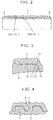
- Figs. 2 to 4 are schematic explanatory diagrams of a premium joint for an oil well pipe, which are vertical cross-sectional views of a cylindrical threaded joint.
- the threaded joint includes a pin component 3 and a box component 1 corresponding thereto.
- the pin component 3 (pin 3) has a male member 7 at its outer surface and a no-threaded portion called a nose 8 (pin nose 8) at an end of the pin 3, which is provided next to the male member 7.
- the nose 8 has a seal 11 at the outer peripheral surface thereof and a torque shoulder 12 at the end face thereof.
- the opposing box component 1 has a female member 5, a seal 13, and a shoulder 14 at the inner surface, which are portions that can be screwed on or come into contact with the male member 7, the seal 11, and the shoulder 12 of the pin 3, respectively.
- Patent Literatures 1 to 6 Examples of the related art of the foregoing premium joint are disclosed in Patent Literatures 1 to 6. A generic threaded joint is further disclosed in US 5,137,310 .
- Patent Literature 1 proposes a threaded joint in which a metal-to-metal seal is provided at a portion of the pin nose 8 close to the threaded portion, and the nose extends lengthwise from the seal to the shoulder to increase external pressure resistance.
- the threaded joint disclosed in Patent Literature 1 is configured such that the pin nose, which is not in contact with the box component, extends lengthwise to be discontinuous to the seal and to avoid decreasing the thickness of the pin nose, to achieve enhancement of not only the external pressure resistance described above but also axial compression resistance.
- Patent Literature 2 describes providing a portion having a shape discontinuous to the seal, called an appendix, from the seal to an end of the pin nose to ensure radial rigidity and decrease axial rigidity to deform the appendix during make-up and to enhance tension resistance due to its recovery under tensile load.
- Patent Literature 3 discloses an example of a radial sealing method in which the pin seal has a large R shape and a small seal taper angle.
- a problem of such a radial sealing method in which the seal taper angle is small is that galling is prone to occur during make-up.
- the susceptibility to the occurrence of galling further increases.
- Patent Literature 4 increases a seal contact area to reduce contact pressure by defining the large radius of a toroidal sealing surface. This measure is effective, thus remarkably reducing the galling tendency of the metal-to-metal seal.
- the contact pressure decreases due to minor trouble because the large R decreases the contact pressure, thus producing a minute leak path in the metal-to-metal seal and this leak is not easy to fix.
- it is physically difficult to separate the metal-to-metal seal from the nose end because of the large R, and thus, ensuring the distance between the metal-to-metal seal and the pin nose to a certain extent or longer results in an excessively small thickness of the pin nose end.
- threaded joints proposed in the related art still have some problems as described above, and thus, there is room for further improvement to satisfactorily meet a variety of performance requirements for the compression resistance, bending resistance, external-pressure sealability, etc of threaded joints described above. Accordingly, it is an object of the present invention to provide a threaded joint for a pipe which is enhanced in terms of sealability, compression resistance, and galling resistance in view of such circumstances.
- the present invention is as follows:
- the present invention can provide a threaded joint for a pipe in which sealability, compression resistance, and galling resistance are enhanced.
- providing the seal at a position away from the nose end to extend the nose from the seal to the shoulder is effective in enhancing the external pressure resistance and the tension resistance and providing the thread with stable performance.
- the inventor and an associated person made a further consideration of the shape around the seal to separate the seal from the nose end (or the shoulder) and to prevent the thickness of the pin nose end from becoming too small.
- the nose outer peripheral surface of the pin component forms an outward convex curve in the axial cross sectional view of the pin component;
- the inner peripheral surface of the box component facing the nose outer peripheral surface of the pin component is a tapered surface that intersects the convex curve of the pin component at two points in the axial cross-sectional view of the box component;
- the nose outer peripheral surface of the pin component and the inner peripheral surface (hereinafter also referred to as a tapered surface) of the box component facing the nose outer peripheral surface form a metal-to-metal seal;
- the convex curve of the pin component is such that a composite R curve, in which a plurality of arcs having different radiuses of curvature, Rs, are connected in sequence to a generating line of a cylindrical portion next to the male member, is curved such that the radiuses of curvature, Rs, of the arcs
- Fig. 1(a), Fig. 1(b) and Fig. 1(c) is a cross-sectional view showing a nose of a threaded joint for a pipe according to an embodiment of the present invention, in which (a) shows a pin component 3, (b) shows a box component 1, and (c) shows a state in which the pin component 3 and the box component 1 are joined together.
- the pin component 3 is provided at an end of a pipe and includes a male member 7, a nose 8 that continues to the pipe side from the male member 7, and a torque shoulder 12 provided at an end of the nose 8.
- the box component 1 includes a female member 5 screwed on the male member 7 of the pin component 3, a tapered surface 20 which is the inner peripheral surface of the box component 1 facing the outer peripheral surface of the nose 8 (nose outer peripheral surface 30) in the state in which the pin component 3 and the box component 1 are joined by the screw connection, and a shoulder 14 that comes into contact with the shoulder 12.
- the nose outer peripheral surface 30 has an external convex curve in the axial cross-sectional view of the pin component 3.
- the inner peripheral surface of the box component 1 facing the nose outer peripheral surface 30 forms a tapered surface 20 (conical surface) having a fixed inclination (referred to as a taper angle) ⁇ with respect to the axial direction of the threaded joint.
- the taper angle ⁇ is set so that the convex curve and the generating line of the tapered surface 20 intersect at two points in the axial cross-sectional view of the threaded joint in an imaginary make up stage without interference between the pin component 3 and the box component 1, and the seal 40 is actually formed in a range (interference area 40a) between the two intersection points.
- the convex curve formed along the nose outer peripheral surface 30 will be described using the composite R curve composed of three arcs shown in Fig. 1(a) .
- This curve is a composite R curve N in which arcs N 1 , N 2 , and N 3 having different radiuses of curvature, R 1 , R 2 , and R 3 , are connected in sequence to a line segment N 0 which is a generating line of a cylindrical portion next to the male member 7.
- This composite R curve N has a curved shape in which the radiuses of curvature of the arcs increase with distance from the male member 7, that is, R 1 ⁇ R 2 ⁇ R 3 . This allows the thickness of the shoulder 12 (shoulder thickness) t at the end of the pin nose 8 to be increased.
- Fig. 1(c) shows, in a broken line, a case in which the convex curve is a single R curve M (a single arc with a radius of curvature, R), and the interference area of its seal is equal to the interference area 40a of the seal 40 of the composite R curve N.
- the shoulder thickness is smaller as compared with the case of the composite R curve N.
- the small shoulder thickness causes insufficient rigidity of the pin nose 8, which precludes the contact pressure of the seal 40 from being properly ensured.
- an attempt to ensure a sufficient shoulder thickness with a single R curve causes the seal 40 to be distant from the male member 7, which is undesirable from the viewpoint of securing sufficient external pressure resistance and tension resistance.
- the composite R curve N has a curved shape such that a tangent on a connection point of an arc and that of a connected arc are aligned with each other. For example, at a connection point between the arcs N 1 and N 2 and at a connection point between the arcs N 2 and N 3 , the tangents of the arcs that are connected together are aligned with each other. Accordingly, the convex curve is shaped in a continuous curve on which no refracting point is present, which reduces improper deformation of the nose.
- angles ⁇ 1 , ⁇ 2 , and ⁇ 3 that the arcs N 1 , N 2 , and N 3 form, respectively, increase with decreasing distance from the male member 7, that is, ⁇ 1 > ⁇ 2 > ⁇ 3 . Otherwise, it is difficult to design the composite R curve within a limited length of the nose 8 of the pin component 3 (the length L of the pin nose in Fig. 1(a) ) or a limited length of the interference area 40a (referred to as a seal contact length).
- any of the connection points in the composite R curve for example, a connection point between the arcs N 1 and N 2 , and a connection point between the arcs N 2 and N 3 , is aligned with a contact start point that indicates a point at which the composite R curve first comes into contact with the tapered surface 20 of the box component 1.
- a portion having a large R, a low contact pressure, and a long contact length and a portion having a small R, a high contact pressure, and a short contact length are formed on the contact pressure distribution of the seal, thereby reducing the tendency to produce a leak path, thus enhancing the sealability.
- the inclination of a tangent at the connection point of the arc may be set smaller than the inclination of the tapered surface of the box component by 0.5 degree at the maximum.
- a deformation such that the end of the pin tapers off occurs due to the radial interference of the pin and the box, which makes the inclination of a tangent to the pin surface at completion of make-up larger than a designed value. Therefore, setting the inclination of a tangent at the contact point of the arc to a value smaller than the inclination of the taper of the box component by 0.5 degrees or less has substantially the same effect as that when the inclinations agree.
- the distance between the contact start point and the end of the male member, x, is less than 0.7L (L is the length of the pin nose, as described above) in the viewpoint of separating the seal from the nose end, and if the distance between the contact start point and the end of the male member is less than 0.2L, the interference between the seal and the thread is prone to occur, and thus, it is preferable to be 0.2L or more. To ensure safety, it is preferable to be 0.3L or more.
- the taper angle ⁇ of the tapered surface 20 of the box component 1 be within ten degrees.
- the taper angle ⁇ (see Fig.1(b) ) within ten degrees, and more preferably, within five degrees, the radial sealing method can be appropriately achieved, and thus, the make up torque dependence on the sealability is relatively decreased.
- the length L of the pin nose (see Fig.1(c) ) be 20 mm or more. This can sufficiently separate the seal from the end of the pin nose, and as a result, can significantly reduce damage to the seal owing to an elastic deformation within the range of separation distance, thus offering the effect of stabilizing the sealability.
- the stabilized sealability allows a sealing interference quantity S (see Fig. 1(c) ) to be relatively small for the radial sealing method, thus reducing galling tendency.
- a relatively small R is preferably set to one inch or less
- a relatively large R is more preferably set to two inches or more
- a further larger R is preferably set to three inches or more.
- at least one of the plurality of Rs of the composite R curve is preferably set to two inches or more (more preferably, three inches or more), and the remaining Rs are preferably set to less than two inches (more preferably, one inch or less).
- the contact length of the seal can easily be ensured, and by setting the remaining Rs preferably to less than two inches (more preferably, one inch or less), high contact pressure can easily be achieved.
- the number of arcs in the composite R curve may be two or three shown in Fig. 1(a) , or alternatively, four or more. Although the increase in the number of arcs increases the seal contact length, thus facilitating enhancement of the sealability, the number of arcs may be designed in accordance with performance actually required for the threaded joint because actual production load and labor, such as size checking, increases.
- the cross-sectional area of the pin component at the contact start point is set to 35% or higher of the cross-sectional area of the main body of a pipe at the end of which the joint is formed (the cross-sectional area of an unprocessed-pin portion).
- the cross-sectional area of the pin component at the contact start point is set to 40% or more of the cross-sectional area of the pipe main body.
- the load flank angle is a load flank angle ⁇ shown in Fig. 5 , that is, an angle ⁇ that a load flank surface 18 forms with a thread-axis orthogonal surface (a surface orthogonal to the axial direction of the threaded joint, ditto for the following).
- the stab flank angle is a stab flank angle ⁇ shown in Fig. 5 , that is, an angle ⁇ that a stab flank surface 19 forms with the thread-axis orthogonal surface.
- the thread gap is a gap G shown in Fig. 5 , that is, the gap G between a thread ridge 7a of the male member and a thread groove 5a of the female member that engages therewith.
- the optimum range of the load flank angle ⁇ is from -5 degrees to four degrees.
- the lower limit of the optimum range is determined from the viewpoint of the galling resistance and the tool life of the thread, and the upper limit is determined from the viewpoint of the bending resistance.
- the optimum range of the stab flank angle ⁇ is from zero degrees to 30 degrees.
- the lower limit of the optimum range is determined from the viewpoint of the galling resistance, the tool life, and the make up performance of the thread, and the upper limit is determined from the viewpoint of axial compression resistance.
- the optimum range of the thread gap G is from 0.01 to 0.1 mm.
- the lower limit is determined from the viewpoint of reducing the galling tendency, and the upper limit is determined from the viewpoint of reducing load on the end of the pin under axial compression load.
- the thread gap G is preferably at least about 0.03 mm in consideration of a lead error during threading. Because of the realization that the thread gap G of about 0.045 mm offers sufficient performance, it may be about 0.045 mm depending on circumstances.
- the overall sealability enhancing effects owing to the determination of one or two or more of the load flank angle, the stab flank angle, and the thread gap as described above are prominent particularly under the condition that the axial tension + internal pressure or external pressure once the axial compression is exerted are loaded.
- the shoulder angle of the shoulder is preferably from zero degrees to 20 degrees.
- a shoulder angle of less than zero degrees is unfavorable for sealability and make-up characteristics.
- a shoulder angle of more than 20 degrees is unfavorable because plastic deformation of the box shoulder and local deformation of the seal tend to occur.
- it is 15 degrees or lower.
- it is preferably seven degrees or lower depending on the circumstances.
- FIG. 1 An evaluation was made of a threaded joint for a pipe according to the present invention shown in Fig. 1 or in which two of the arcs of the composite R curve in Fig. 1(a) are connected via a line segment.
- Table 1 and 2 shows the sizes, shapes and evaluation results of examples of the present invention and comparative examples. All the pin components were formed at ends of pipes with an external diameter of 244.48 mm and a wall thickness of 13.84 mm. The threads have 5 TPI (five threads per inch).
- a leak test based on ISO 13679: 2002 was simulated as evaluation by FEM analysis, in which the contact pressure area (ksi ⁇ inch) of the seal was evaluated. The contact pressure area is obtained by integrating the contact pressure with the seal contact area.
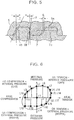
- This leak test is a load test on a threaded joint for a pipe based on a biaxial stress corresponding to 95% of material yield conditions, an inner pressure, a smaller one of a biaxial stress corresponding to the collapse conditions described in ISO 10400: 2007 and a biaxial stress corresponding to 95% of material yield conditions, and an external pressure, which are imposed in the schedule shown in Fig. 6 .
- Table 1 and 2 shows, in addition to the sizes of the individual components of the threaded joints, the contact pressure areas and galling indexes obtained by FEM calculation and the maximum and minimum seal interference quantities determined by the actual physical test and the repeated make-up test.
- the seal interference quantities on Table 1 and 2 are values per diameter, which correspond to the seal interference quantity S ⁇ 2, shown in Fig. 1(c) .
- the contact pressure areas under the inner pressure condition in the FEM calculation in all the examples were the minimum values (corresponding to a state in which leak is most prone to occur) in the vicinity of load steps L3 and L18 (biaxial tension stress + inner pressure) in the schedule in Fig. 6 .
- the load point is not specified in ISO 13679, it is the most severe condition for the inner pressure + tension conditions and is sometimes needed, and thus, it was used here for comparison.
- the contact pressure areas under the external pressure conditions in the FEM calculation in all the examples were the minimum values in the vicinity of a load step L15 (biaxial tension stress + external pressure) in the schedule in Fig. 6 .
- Table 1 and 2 shows the minimum values of the contact pressure areas in the individual examples as relative minimum values.
- the inner pressure is loaded with gas and the external pressure is loaded with water, and thus, susceptibility to leakage differs; therefore, relative minimum values were obtained with reference to the respective minimum values under the inner pressure condition and the external pressure condition.
- the minimum value at L3 and L18 the smallest minimum value in all the examples for L3 and L18 was set at 100, and other others were expressed as ratios thereto.
- the minimum value at L15 the smallest minimum value in all the examples for L15 was set at 100, and the others were expressed as ratios thereto.
- the load step L18 after compression hysteresis was once subjected exhibited sealability lower than the sealability at the load step L3, which is the same load point as that before the compression hysteresis was subjected, which is significant in, in particular, Comparative Example 3 in which no sufficient shoulder thickness.
- the examples of the present invention exhibited good sealability at L18 after being subjected to compression hysteresis.
- Table 1 and 2 shows the maximum values of the galling indexes of the individual examples as relative maximum values (the maximum value in all the examples is set at 100, and the others are expressed as ratios thereto).
- Table 3 shows evaluation results with other sizes.
- Object materials have an outside diameter of 139.7 mm, a wall thickness of 7.72 mm, and 5 TPI and have an outside diameter of 346.08 mm, a thickness of 15.88 mm, and 4 TPI.
- Examples of the present invention exhibited good sealability after being subjected to compression hysteresis and high galling performance during make-up with all sizes.
- Tables 1, 2 and 3 show that the examples of the present invention achieved threaded joints having galling indexes smaller than or equal to the comparative examples and having wide settable seal interference quantity ranges wide and high sealability and galling resistance although the contact pressure areas (contact pressure areas) were higher.
Landscapes
- Engineering & Computer Science (AREA)
- General Engineering & Computer Science (AREA)
- Mechanical Engineering (AREA)
- Geology (AREA)
- Life Sciences & Earth Sciences (AREA)
- Mining & Mineral Resources (AREA)
- Environmental & Geological Engineering (AREA)
- Fluid Mechanics (AREA)
- General Life Sciences & Earth Sciences (AREA)
- Geochemistry & Mineralogy (AREA)
- Physics & Mathematics (AREA)
- Non-Disconnectible Joints And Screw-Threaded Joints (AREA)
- Earth Drilling (AREA)
Claims (9)
- Gewindeverbindung für ein Rohr, die umfasst:eine Bolzen-Komponente (3), die ein Einführ-Element (7), einen Ansatz (8), der sich von dem Einführ-Element (7) zu einem Rohr-Ende erstreckt, sowie eine Schulter (12) enthält, die sich an einem Ende des Ansatzes (8) befindet; undeine Muffen-Komponente (1), die ein Aufnahme-Element (5), das auf das Einführ-Element (7) aufgeschraubt ist, eine Innenumfangsfläche (20), die der Außenumfangsfläche (30) des Ansatzes (8) der Bolzen-Komponente (3) zugewandt ist, sowie eine Schulter (14) enthält, die in Kontakt mit der Schulter (12) der Bolzen-Komponente (3) kommt,wobei die Bolzen-Komponente (3) und die Muffen-Komponente (1) über die Schraubverbindung so verbunden sind, dass die Ansatz-Außenumfangsfläche (30) der Bolzen-Komponente (3) und die Innenumfangsfläche (20) der Muffen-Komponente (1) so in Metall-Metall-Kontakt kommen, dass die Kontakt-Grenzfläche eine Dichtungsfläche bildet, dadurch gekennzeichnet, dassdie Ansatz-Außenumfangsfläche (30) der Bolzen-Komponente (3), in der Axialschnittansicht der Bolzen-Komponente eine nach außen konvexe Kurve bildet und die konvexe Kurve so geformt ist, dass eine zusammengesetzte R-Kurve, in der eine Vielzahl nach außen konvexer Bögen mit unterschiedlichen Krümmungsradien Rs aufeinanderfolgend mit einer erzeugenden Linie eines zylindrischen Abschnitts neben dem Einführ-Element (7) verbunden sind, so gekrümmt ist, dass die Krümmungsradien Rs der Bögen mit dem Abstand zu dem Einführ-Element (7) größer werden und Tangenten an Verbindungspunkten der Bögen auf diejenigen entsprechender damit verbundener Bögen ausgerichtet sind, und die Innenumfangsfläche (20) der Muffen-Komponente (1) eine konische Fläche ist, die sich mit der Ansatz-Außenumfangsfläche (30) der Bolzen-Komponente (3) überlagert, wenn sie mit der Bolzen-Komponente (3) verbunden ist.
- Gewindeverbindung für ein Rohr nach Anspruch 1, wobei Winkel, die die einzelnen Bögen in der zusammengesetzten R-Kurve bilden, mit abnehmendem Abstand zu dem Einführ-Element (7) größer werden.
- Gewindeverbindung für ein Rohr nach Anspruch 1 oder 2, wobei beliebige der Verbindungspunkte in der zusammengesetzten R-Kurve als ein Kontakt-Anfangspunkt mit der konischen Fläche dienen.
- Gewindeverbindung für ein Rohr nach einem der Ansprüche 1 bis 3, wobei ein Winkel, den die konische Fläche zu der axialen Richtung der Verbindung bildet, innerhalb von 10° liegt.
- Gewindeverbindung für ein Rohr nach einem der Ansprüche 1 bis 4, wobei der Ansatz (8) der Bolzen-Komponente (3) eine Länge von 20 mm oder mehr hat.
- Gewindeverbindung für ein Rohr nach einem der Ansprüche 1 bis 5, wobei Spielflanken-Winkel (γ) des Einführelementes (7) und des Aufnahme-Elementes (5) innerhalb des Bereiches von 0° bis 30° liegen.
- Gewindeverbindung für ein Rohr nach einem der Ansprüche 1 bis 6, wobei Lastflanken-Winkel (β) des Einführ-Elementes (7) und des Aufnahme-Elementes (5) innerhalb des Bereiches von -5° bis 4° liegen.
- Gewindeverbindung für ein Rohr nach einem der Ansprüche 1 bis 7, wobei ein Ansatz-Winkel des Ansatzes innerhalb des Bereiches von 0° bis 20° liegt.
- Gewindeverbindung für ein Rohr nach einem der Ansprüche 1 bis 8, wobei ein Gewindespalt zwischen dem Einführ-Element (7) und dem Aufnahme-Element (5) innerhalb des Bereiches von 0,01 bis 0,1 mm liegt.
Priority Applications (1)
| Application Number | Priority Date | Filing Date | Title |
|---|---|---|---|
| EP17156626.8A EP3196524B1 (de) | 2010-06-30 | 2011-06-22 | Schraubverbindung für rohr |
Applications Claiming Priority (4)
| Application Number | Priority Date | Filing Date | Title |
|---|---|---|---|
| JP2010149547 | 2010-06-30 | ||
| JP2010289785 | 2010-12-27 | ||
| JP2011101329A JP4930647B1 (ja) | 2010-06-30 | 2011-04-28 | 管用ねじ継手 |
| PCT/JP2011/064862 WO2012002409A1 (ja) | 2010-06-30 | 2011-06-22 | 管用ねじ継手 |
Related Child Applications (2)
| Application Number | Title | Priority Date | Filing Date |
|---|---|---|---|
| EP17156626.8A Division-Into EP3196524B1 (de) | 2010-06-30 | 2011-06-22 | Schraubverbindung für rohr |
| EP17156626.8A Division EP3196524B1 (de) | 2010-06-30 | 2011-06-22 | Schraubverbindung für rohr |
Publications (3)
| Publication Number | Publication Date |
|---|---|
| EP2589846A1 EP2589846A1 (de) | 2013-05-08 |
| EP2589846A4 EP2589846A4 (de) | 2015-04-01 |
| EP2589846B1 true EP2589846B1 (de) | 2017-06-14 |
Family
ID=45402114
Family Applications (2)
| Application Number | Title | Priority Date | Filing Date |
|---|---|---|---|
| EP11800871.3A Active EP2589846B1 (de) | 2010-06-30 | 2011-06-22 | Rohrverschraubungskupplung |
| EP17156626.8A Active EP3196524B1 (de) | 2010-06-30 | 2011-06-22 | Schraubverbindung für rohr |
Family Applications After (1)
| Application Number | Title | Priority Date | Filing Date |
|---|---|---|---|
| EP17156626.8A Active EP3196524B1 (de) | 2010-06-30 | 2011-06-22 | Schraubverbindung für rohr |
Country Status (13)
| Country | Link |
|---|---|
| US (1) | US9194190B2 (de) |
| EP (2) | EP2589846B1 (de) |
| JP (1) | JP4930647B1 (de) |
| CN (2) | CN202469289U (de) |
| AR (1) | AR081782A1 (de) |
| AU (1) | AU2011272607B2 (de) |
| BR (1) | BR112012033452B1 (de) |
| CA (1) | CA2801204C (de) |
| MX (1) | MX336628B (de) |
| MY (1) | MY156120A (de) |
| RU (1) | RU2522756C1 (de) |
| SA (1) | SA111320568B1 (de) |
| WO (1) | WO2012002409A1 (de) |
Families Citing this family (28)
| Publication number | Priority date | Publication date | Assignee | Title |
|---|---|---|---|---|
| JP4930647B1 (ja) * | 2010-06-30 | 2012-05-16 | Jfeスチール株式会社 | 管用ねじ継手 |
| WO2012112570A1 (en) | 2011-02-14 | 2012-08-23 | The Regents Of The University Of California | SORAFENIB DERIVATIVES AS sEH INHIBITORS |
| JP5849749B2 (ja) * | 2011-02-28 | 2016-02-03 | Jfeスチール株式会社 | 管用ねじ継手 |
| JP5923911B2 (ja) * | 2011-03-22 | 2016-05-25 | Jfeスチール株式会社 | 鋼管用ねじ継手 |
| JP5891700B2 (ja) * | 2011-10-17 | 2016-03-23 | Jfeスチール株式会社 | 管のねじ継手 |
| JP5924152B2 (ja) * | 2012-06-20 | 2016-05-25 | Jfeスチール株式会社 | 鋼管用ねじ継手 |
| RU2500875C1 (ru) * | 2012-07-20 | 2013-12-10 | Общество С Ограниченной Ответственностью "Тмк-Премиум Сервис" | Высокогерметичное резьбовое соединение насосно-компрессорных труб (варианты) |
| JP6020087B2 (ja) * | 2012-11-22 | 2016-11-02 | Jfeスチール株式会社 | 管用ねじ継手 |
| RU2504710C1 (ru) * | 2012-12-13 | 2014-01-20 | Общество С Ограниченной Ответственностью "Тмк-Премиум Сервис" | Высокогерметичное резьбовое соединение обсадных труб (варианты) |
| WO2014115191A1 (ja) * | 2013-01-28 | 2014-07-31 | Jfeスチール株式会社 | 鋼管用ねじ継手 |
| JP5803953B2 (ja) | 2013-02-18 | 2015-11-04 | Jfeスチール株式会社 | 管接続用ねじ継手 |
| JP6220880B2 (ja) | 2013-09-06 | 2017-10-25 | 新日鐵住金株式会社 | 鋼管用ねじ継手 |
| WO2016113790A1 (ja) * | 2015-01-15 | 2016-07-21 | Jfeスチール株式会社 | 管用ねじ継手 |
| US10041307B2 (en) | 2015-01-22 | 2018-08-07 | National Oilwell Varco, L.P. | Balanced thread form, tubulars employing the same, and methods relating thereto |
| MY189310A (en) * | 2016-02-19 | 2022-02-03 | Jfe Steel Corp | Threaded joint for oil well tubing |
| UA122027C2 (uk) * | 2016-08-24 | 2020-08-25 | ДжФЕ СТІЛ КОРПОРЕЙШН | Різьбове з'єднання для трубних виробів нафтопромислового сортаменту |
| FR3060701A1 (fr) * | 2016-12-16 | 2018-06-22 | Vallourec Oil And Gas France | Joint filete pour composant tubulaire |
| CA3064361C (en) * | 2017-05-22 | 2022-04-12 | Nippon Steel Corporation | Threaded connection for steel pipes |
| US11143337B2 (en) * | 2017-11-09 | 2021-10-12 | Nippon Steel Corporation | Threaded connection for steel pipe |
| RU2756365C9 (ru) * | 2018-08-21 | 2021-10-06 | Ниппон Стил Корпорейшн | Резьбовое соединение для стальных труб |
| CN109915667B (zh) * | 2019-04-15 | 2020-02-07 | 大连长之琳科技发展有限公司 | 一种内旋滚压式密封接头、轻型直通管接头及其应用 |
| CN110608322B (zh) * | 2019-09-11 | 2024-04-12 | 江苏璞腾油气装备有限公司 | 一种四线海洋隔水管接头 |
| MX2022003070A (es) | 2020-01-17 | 2022-04-18 | Nippon Steel Corp | Conexion roscada para tubo. |
| AU2020423747B2 (en) * | 2020-01-17 | 2023-09-07 | Nippon Steel Corporation | Threaded connection for pipe |
| EP4092304B1 (de) * | 2020-01-17 | 2024-02-07 | Nippon Steel Corporation | Gewindeanschluss für rohr |
| WO2022070367A1 (ja) | 2020-09-30 | 2022-04-07 | Jfeスチール株式会社 | 管のねじ継手およびその接続方法 |
| DE202020107520U1 (de) * | 2020-12-23 | 2021-02-01 | L.L.C. "Interpipe Management" | Dichte Metallrohrgewindeverbindung |
| FR3121492B1 (fr) * | 2021-03-31 | 2023-02-24 | Vallourec Oil & Gas France | Dimensionnement d’un jeu axial de filetage |
Family Cites Families (23)
| Publication number | Priority date | Publication date | Assignee | Title |
|---|---|---|---|---|
| DE1533619A1 (de) | 1967-04-28 | 1970-06-11 | ||
| JPS58157087U (ja) * | 1982-04-16 | 1983-10-20 | 日本鋼管株式会社 | 油井管用ネジ継手 |
| US4588213A (en) * | 1983-10-05 | 1986-05-13 | Thread Technology International, Inc. | Threaded pipe connection |
| JPS6144068A (ja) | 1984-08-07 | 1986-03-03 | 三菱電機株式会社 | 鉄道車両の蛇行動防止装置 |
| JPS6144068U (ja) | 1984-08-27 | 1986-03-24 | 株式会社 コスモ計器 | 絞り装置 |
| US5137310A (en) * | 1990-11-27 | 1992-08-11 | Vallourec Industries | Assembly arrangement using frustoconical screwthreads for tubes |
| JP2705506B2 (ja) | 1993-03-24 | 1998-01-28 | 住友金属工業株式会社 | 油井管用ねじ継手 |
| FR2725773B1 (fr) * | 1994-10-13 | 1996-11-29 | Vallourec Oil & Gas | Assemblage filete pour tubes |
| FR2733570B1 (fr) * | 1995-04-28 | 1997-06-20 | Vallourec Oil & Gas | Assemblage filete pour tubes |
| FR2761450B1 (fr) * | 1997-03-27 | 1999-05-07 | Vallourec Mannesmann Oil & Gas | Joint filete pour tubes |
| DE19836088C1 (de) * | 1998-07-31 | 2000-02-03 | Mannesmann Ag | Rohrverbindung |
| JP2001124253A (ja) | 1999-10-29 | 2001-05-11 | Kawasaki Steel Corp | 鋼管用ネジ継手 |
| MXPA02012145A (es) * | 2000-06-09 | 2004-08-19 | Sumitomo Metal Ind | Junta de tuberia. |
| FR2833335B1 (fr) * | 2001-12-07 | 2007-05-18 | Vallourec Mannesmann Oil & Gas | Joint filete tubulaire superieur contenant au moins un element filete avec levre d'extremite |
| ITRM20020445A1 (it) | 2002-09-06 | 2004-03-07 | Tenaris Connections Bv | Giunzione filettata per tubi. |
| UA82694C2 (uk) | 2003-06-06 | 2008-05-12 | Sumitomo Metal Ind | Нарізне з'єднання для сталевих труб |
| FR2863681B1 (fr) * | 2003-12-11 | 2006-02-24 | Vallourec Mannesmann Oil & Gas | Joint tubulaire a filetages coniques resistant a la fatigue |
| JP2007205361A (ja) * | 2004-08-27 | 2007-08-16 | Sumitomo Metal Ind Ltd | 鋼管用ねじ継手 |
| FR2913746B1 (fr) * | 2007-03-14 | 2011-06-24 | Vallourec Mannesmann Oil & Gas | Joint filete tubulaire etanche pour sollicitations de pression interieure et exterieure |
| JP5250990B2 (ja) * | 2007-03-28 | 2013-07-31 | 新日鐵住金株式会社 | 油井管用ねじ継手 |
| FR2925946B1 (fr) * | 2007-12-28 | 2009-12-11 | Vallourec Mannesmann Oil & Gas | Joint filete tubulaire etanche et resistant a des sollicitations successives de pressions |
| CN102187139B (zh) * | 2008-10-20 | 2013-06-05 | 住友金属工业株式会社 | 钢管用螺纹接头 |
| JP4930647B1 (ja) * | 2010-06-30 | 2012-05-16 | Jfeスチール株式会社 | 管用ねじ継手 |
-
2011
- 2011-04-28 JP JP2011101329A patent/JP4930647B1/ja active Active
- 2011-06-22 EP EP11800871.3A patent/EP2589846B1/de active Active
- 2011-06-22 WO PCT/JP2011/064862 patent/WO2012002409A1/ja not_active Ceased
- 2011-06-22 RU RU2013103811/06A patent/RU2522756C1/ru active
- 2011-06-22 EP EP17156626.8A patent/EP3196524B1/de active Active
- 2011-06-22 AU AU2011272607A patent/AU2011272607B2/en not_active Ceased
- 2011-06-22 BR BR112012033452-2A patent/BR112012033452B1/pt active IP Right Grant
- 2011-06-22 MX MX2012014880A patent/MX336628B/es unknown
- 2011-06-22 CA CA2801204A patent/CA2801204C/en active Active
- 2011-06-22 US US13/807,883 patent/US9194190B2/en active Active
- 2011-06-22 MY MYPI2012005551A patent/MY156120A/en unknown
- 2011-06-29 AR ARP110102284A patent/AR081782A1/es active IP Right Grant
- 2011-06-29 SA SA111320568A patent/SA111320568B1/ar unknown
- 2011-06-30 CN CN2011202356277U patent/CN202469289U/zh not_active Expired - Fee Related
- 2011-06-30 CN CN201110189469.0A patent/CN102313085B/zh active Active
Also Published As
| Publication number | Publication date |
|---|---|
| BR112012033452A2 (pt) | 2016-12-13 |
| WO2012002409A1 (ja) | 2012-01-05 |
| JP4930647B1 (ja) | 2012-05-16 |
| AR081782A1 (es) | 2012-10-17 |
| EP2589846A1 (de) | 2013-05-08 |
| JP2012149760A (ja) | 2012-08-09 |
| CN102313085A (zh) | 2012-01-11 |
| MX336628B (es) | 2016-01-26 |
| EP2589846A4 (de) | 2015-04-01 |
| BR112012033452B1 (pt) | 2020-09-29 |
| AU2011272607A1 (en) | 2012-12-20 |
| CN102313085B (zh) | 2015-10-14 |
| CN202469289U (zh) | 2012-10-03 |
| AU2011272607B2 (en) | 2015-03-12 |
| US20130181442A1 (en) | 2013-07-18 |
| US9194190B2 (en) | 2015-11-24 |
| EP3196524B1 (de) | 2021-06-09 |
| MX2012014880A (es) | 2013-01-24 |
| RU2522756C1 (ru) | 2014-07-20 |
| EP3196524A1 (de) | 2017-07-26 |
| CA2801204C (en) | 2016-08-09 |
| CA2801204A1 (en) | 2012-01-05 |
| SA111320568B1 (ar) | 2014-05-21 |
| MY156120A (en) | 2016-01-15 |
Similar Documents
| Publication | Publication Date | Title |
|---|---|---|
| EP2589846B1 (de) | Rohrverschraubungskupplung | |
| CN102187139B (zh) | 钢管用螺纹接头 | |
| EP2682658B1 (de) | Schraubverbindung für rohre | |
| EP2690336A1 (de) | Schraubverbindung für stahlrohre | |
| JP5660308B2 (ja) | 鋼管用ねじ継手 | |
| CN104775761B (zh) | 极厚壁油井管用螺纹接头 | |
| EP2871396B1 (de) | Gewinderohrverbindung | |
| CN104453738A (zh) | 一种气密封套管接头 | |
| EP3246611B1 (de) | Schraubverbindung für röhre | |
| EP2937612B1 (de) | Schraubverbindung für rohre | |
| JP5673089B2 (ja) | 鋼管用ねじ継手 | |
| EP2977662B1 (de) | Gewindeverbindungsstück für ein ölbohrungsrohr | |
| EP2949983A1 (de) | Schraubverbindung für stahlrohre | |
| JP2012067909A (ja) | 鋼管用ねじ継手 |
Legal Events
| Date | Code | Title | Description |
|---|---|---|---|
| PUAI | Public reference made under article 153(3) epc to a published international application that has entered the european phase |
Free format text: ORIGINAL CODE: 0009012 |
|
| 17P | Request for examination filed |
Effective date: 20130130 |
|
| AK | Designated contracting states |
Kind code of ref document: A1 Designated state(s): AL AT BE BG CH CY CZ DE DK EE ES FI FR GB GR HR HU IE IS IT LI LT LU LV MC MK MT NL NO PL PT RO RS SE SI SK SM TR |
|
| DAX | Request for extension of the european patent (deleted) | ||
| A4 | Supplementary search report drawn up and despatched |
Effective date: 20150227 |
|
| RIC1 | Information provided on ipc code assigned before grant |
Ipc: F16L 15/04 20060101AFI20150223BHEP Ipc: E21B 17/042 20060101ALI20150223BHEP Ipc: F16L 15/00 20060101ALI20150223BHEP |
|
| 17Q | First examination report despatched |
Effective date: 20160311 |
|
| GRAP | Despatch of communication of intention to grant a patent |
Free format text: ORIGINAL CODE: EPIDOSNIGR1 |
|
| INTG | Intention to grant announced |
Effective date: 20160923 |
|
| GRAJ | Information related to disapproval of communication of intention to grant by the applicant or resumption of examination proceedings by the epo deleted |
Free format text: ORIGINAL CODE: EPIDOSDIGR1 |
|
| STAA | Information on the status of an ep patent application or granted ep patent |
Free format text: STATUS: EXAMINATION IS IN PROGRESS |
|
| GRAP | Despatch of communication of intention to grant a patent |
Free format text: ORIGINAL CODE: EPIDOSNIGR1 |
|
| STAA | Information on the status of an ep patent application or granted ep patent |
Free format text: STATUS: GRANT OF PATENT IS INTENDED |
|
| INTC | Intention to grant announced (deleted) | ||
| INTG | Intention to grant announced |
Effective date: 20170102 |
|
| GRAS | Grant fee paid |
Free format text: ORIGINAL CODE: EPIDOSNIGR3 |
|
| GRAA | (expected) grant |
Free format text: ORIGINAL CODE: 0009210 |
|
| STAA | Information on the status of an ep patent application or granted ep patent |
Free format text: STATUS: THE PATENT HAS BEEN GRANTED |
|
| AK | Designated contracting states |
Kind code of ref document: B1 Designated state(s): AL AT BE BG CH CY CZ DE DK EE ES FI FR GB GR HR HU IE IS IT LI LT LU LV MC MK MT NL NO PL PT RO RS SE SI SK SM TR |
|
| REG | Reference to a national code |
Ref country code: GB Ref legal event code: FG4D |
|
| REG | Reference to a national code |
Ref country code: CH Ref legal event code: EP Ref country code: AT Ref legal event code: REF Ref document number: 901318 Country of ref document: AT Kind code of ref document: T Effective date: 20170615 |
|
| REG | Reference to a national code |
Ref country code: IE Ref legal event code: FG4D |
|
| REG | Reference to a national code |
Ref country code: DE Ref legal event code: R096 Ref document number: 602011038763 Country of ref document: DE |
|
| REG | Reference to a national code |
Ref country code: FR Ref legal event code: PLFP Year of fee payment: 7 |
|
| REG | Reference to a national code |
Ref country code: NL Ref legal event code: FP |
|
| REG | Reference to a national code |
Ref country code: NO Ref legal event code: T2 Effective date: 20170614 |
|
| REG | Reference to a national code |
Ref country code: LT Ref legal event code: MG4D |
|
| PG25 | Lapsed in a contracting state [announced via postgrant information from national office to epo] |
Ref country code: HR Free format text: LAPSE BECAUSE OF FAILURE TO SUBMIT A TRANSLATION OF THE DESCRIPTION OR TO PAY THE FEE WITHIN THE PRESCRIBED TIME-LIMIT Effective date: 20170614 Ref country code: GR Free format text: LAPSE BECAUSE OF FAILURE TO SUBMIT A TRANSLATION OF THE DESCRIPTION OR TO PAY THE FEE WITHIN THE PRESCRIBED TIME-LIMIT Effective date: 20170915 Ref country code: LT Free format text: LAPSE BECAUSE OF FAILURE TO SUBMIT A TRANSLATION OF THE DESCRIPTION OR TO PAY THE FEE WITHIN THE PRESCRIBED TIME-LIMIT Effective date: 20170614 Ref country code: FI Free format text: LAPSE BECAUSE OF FAILURE TO SUBMIT A TRANSLATION OF THE DESCRIPTION OR TO PAY THE FEE WITHIN THE PRESCRIBED TIME-LIMIT Effective date: 20170614 Ref country code: ES Free format text: LAPSE BECAUSE OF FAILURE TO SUBMIT A TRANSLATION OF THE DESCRIPTION OR TO PAY THE FEE WITHIN THE PRESCRIBED TIME-LIMIT Effective date: 20170614 |
|
| REG | Reference to a national code |
Ref country code: AT Ref legal event code: MK05 Ref document number: 901318 Country of ref document: AT Kind code of ref document: T Effective date: 20170614 |
|
| PG25 | Lapsed in a contracting state [announced via postgrant information from national office to epo] |
Ref country code: LV Free format text: LAPSE BECAUSE OF FAILURE TO SUBMIT A TRANSLATION OF THE DESCRIPTION OR TO PAY THE FEE WITHIN THE PRESCRIBED TIME-LIMIT Effective date: 20170614 Ref country code: RS Free format text: LAPSE BECAUSE OF FAILURE TO SUBMIT A TRANSLATION OF THE DESCRIPTION OR TO PAY THE FEE WITHIN THE PRESCRIBED TIME-LIMIT Effective date: 20170614 Ref country code: SE Free format text: LAPSE BECAUSE OF FAILURE TO SUBMIT A TRANSLATION OF THE DESCRIPTION OR TO PAY THE FEE WITHIN THE PRESCRIBED TIME-LIMIT Effective date: 20170614 Ref country code: BG Free format text: LAPSE BECAUSE OF FAILURE TO SUBMIT A TRANSLATION OF THE DESCRIPTION OR TO PAY THE FEE WITHIN THE PRESCRIBED TIME-LIMIT Effective date: 20170914 |
|
| PG25 | Lapsed in a contracting state [announced via postgrant information from national office to epo] |
Ref country code: RO Free format text: LAPSE BECAUSE OF FAILURE TO SUBMIT A TRANSLATION OF THE DESCRIPTION OR TO PAY THE FEE WITHIN THE PRESCRIBED TIME-LIMIT Effective date: 20170614 Ref country code: CZ Free format text: LAPSE BECAUSE OF FAILURE TO SUBMIT A TRANSLATION OF THE DESCRIPTION OR TO PAY THE FEE WITHIN THE PRESCRIBED TIME-LIMIT Effective date: 20170614 Ref country code: SK Free format text: LAPSE BECAUSE OF FAILURE TO SUBMIT A TRANSLATION OF THE DESCRIPTION OR TO PAY THE FEE WITHIN THE PRESCRIBED TIME-LIMIT Effective date: 20170614 Ref country code: EE Free format text: LAPSE BECAUSE OF FAILURE TO SUBMIT A TRANSLATION OF THE DESCRIPTION OR TO PAY THE FEE WITHIN THE PRESCRIBED TIME-LIMIT Effective date: 20170614 Ref country code: AT Free format text: LAPSE BECAUSE OF FAILURE TO SUBMIT A TRANSLATION OF THE DESCRIPTION OR TO PAY THE FEE WITHIN THE PRESCRIBED TIME-LIMIT Effective date: 20170614 |
|
| REG | Reference to a national code |
Ref country code: CH Ref legal event code: PL |
|
| PG25 | Lapsed in a contracting state [announced via postgrant information from national office to epo] |
Ref country code: SM Free format text: LAPSE BECAUSE OF FAILURE TO SUBMIT A TRANSLATION OF THE DESCRIPTION OR TO PAY THE FEE WITHIN THE PRESCRIBED TIME-LIMIT Effective date: 20170614 Ref country code: IS Free format text: LAPSE BECAUSE OF FAILURE TO SUBMIT A TRANSLATION OF THE DESCRIPTION OR TO PAY THE FEE WITHIN THE PRESCRIBED TIME-LIMIT Effective date: 20171014 Ref country code: PL Free format text: LAPSE BECAUSE OF FAILURE TO SUBMIT A TRANSLATION OF THE DESCRIPTION OR TO PAY THE FEE WITHIN THE PRESCRIBED TIME-LIMIT Effective date: 20170614 |
|
| REG | Reference to a national code |
Ref country code: DE Ref legal event code: R097 Ref document number: 602011038763 Country of ref document: DE |
|
| REG | Reference to a national code |
Ref country code: IE Ref legal event code: MM4A |
|
| PG25 | Lapsed in a contracting state [announced via postgrant information from national office to epo] |
Ref country code: MC Free format text: LAPSE BECAUSE OF FAILURE TO SUBMIT A TRANSLATION OF THE DESCRIPTION OR TO PAY THE FEE WITHIN THE PRESCRIBED TIME-LIMIT Effective date: 20170614 |
|
| PLBE | No opposition filed within time limit |
Free format text: ORIGINAL CODE: 0009261 |
|
| STAA | Information on the status of an ep patent application or granted ep patent |
Free format text: STATUS: NO OPPOSITION FILED WITHIN TIME LIMIT |
|
| PG25 | Lapsed in a contracting state [announced via postgrant information from national office to epo] |
Ref country code: LU Free format text: LAPSE BECAUSE OF NON-PAYMENT OF DUE FEES Effective date: 20170622 Ref country code: CH Free format text: LAPSE BECAUSE OF NON-PAYMENT OF DUE FEES Effective date: 20170630 Ref country code: IE Free format text: LAPSE BECAUSE OF NON-PAYMENT OF DUE FEES Effective date: 20170622 Ref country code: LI Free format text: LAPSE BECAUSE OF NON-PAYMENT OF DUE FEES Effective date: 20170630 Ref country code: DK Free format text: LAPSE BECAUSE OF FAILURE TO SUBMIT A TRANSLATION OF THE DESCRIPTION OR TO PAY THE FEE WITHIN THE PRESCRIBED TIME-LIMIT Effective date: 20170614 |
|
| REG | Reference to a national code |
Ref country code: FR Ref legal event code: PLFP Year of fee payment: 8 |
|
| 26N | No opposition filed |
Effective date: 20180315 |
|
| REG | Reference to a national code |
Ref country code: BE Ref legal event code: MM Effective date: 20170630 |
|
| PG25 | Lapsed in a contracting state [announced via postgrant information from national office to epo] |
Ref country code: SI Free format text: LAPSE BECAUSE OF FAILURE TO SUBMIT A TRANSLATION OF THE DESCRIPTION OR TO PAY THE FEE WITHIN THE PRESCRIBED TIME-LIMIT Effective date: 20170614 Ref country code: BE Free format text: LAPSE BECAUSE OF NON-PAYMENT OF DUE FEES Effective date: 20170630 |
|
| PG25 | Lapsed in a contracting state [announced via postgrant information from national office to epo] |
Ref country code: MT Free format text: LAPSE BECAUSE OF NON-PAYMENT OF DUE FEES Effective date: 20170622 |
|
| PG25 | Lapsed in a contracting state [announced via postgrant information from national office to epo] |
Ref country code: HU Free format text: LAPSE BECAUSE OF FAILURE TO SUBMIT A TRANSLATION OF THE DESCRIPTION OR TO PAY THE FEE WITHIN THE PRESCRIBED TIME-LIMIT; INVALID AB INITIO Effective date: 20110622 |
|
| PG25 | Lapsed in a contracting state [announced via postgrant information from national office to epo] |
Ref country code: CY Free format text: LAPSE BECAUSE OF NON-PAYMENT OF DUE FEES Effective date: 20170614 |
|
| PG25 | Lapsed in a contracting state [announced via postgrant information from national office to epo] |
Ref country code: MK Free format text: LAPSE BECAUSE OF FAILURE TO SUBMIT A TRANSLATION OF THE DESCRIPTION OR TO PAY THE FEE WITHIN THE PRESCRIBED TIME-LIMIT Effective date: 20170614 |
|
| PG25 | Lapsed in a contracting state [announced via postgrant information from national office to epo] |
Ref country code: TR Free format text: LAPSE BECAUSE OF FAILURE TO SUBMIT A TRANSLATION OF THE DESCRIPTION OR TO PAY THE FEE WITHIN THE PRESCRIBED TIME-LIMIT Effective date: 20170614 |
|
| PG25 | Lapsed in a contracting state [announced via postgrant information from national office to epo] |
Ref country code: PT Free format text: LAPSE BECAUSE OF FAILURE TO SUBMIT A TRANSLATION OF THE DESCRIPTION OR TO PAY THE FEE WITHIN THE PRESCRIBED TIME-LIMIT Effective date: 20170614 |
|
| PG25 | Lapsed in a contracting state [announced via postgrant information from national office to epo] |
Ref country code: AL Free format text: LAPSE BECAUSE OF FAILURE TO SUBMIT A TRANSLATION OF THE DESCRIPTION OR TO PAY THE FEE WITHIN THE PRESCRIBED TIME-LIMIT Effective date: 20170614 |
|
| P01 | Opt-out of the competence of the unified patent court (upc) registered |
Effective date: 20230512 |
|
| PGFP | Annual fee paid to national office [announced via postgrant information from national office to epo] |
Ref country code: NO Payment date: 20230608 Year of fee payment: 13 Ref country code: NL Payment date: 20230515 Year of fee payment: 13 |
|
| REG | Reference to a national code |
Ref country code: NL Ref legal event code: MM Effective date: 20240701 |
|
| PG25 | Lapsed in a contracting state [announced via postgrant information from national office to epo] |
Ref country code: NL Free format text: LAPSE BECAUSE OF NON-PAYMENT OF DUE FEES Effective date: 20240701 |
|
| PG25 | Lapsed in a contracting state [announced via postgrant information from national office to epo] |
Ref country code: NL Free format text: LAPSE BECAUSE OF NON-PAYMENT OF DUE FEES Effective date: 20240701 |
|
| PG25 | Lapsed in a contracting state [announced via postgrant information from national office to epo] |
Ref country code: NO Free format text: LAPSE BECAUSE OF NON-PAYMENT OF DUE FEES Effective date: 20240630 |
|
| PGFP | Annual fee paid to national office [announced via postgrant information from national office to epo] |
Ref country code: DE Payment date: 20250429 Year of fee payment: 15 |
|
| PGFP | Annual fee paid to national office [announced via postgrant information from national office to epo] |
Ref country code: GB Payment date: 20250501 Year of fee payment: 15 |
|
| PGFP | Annual fee paid to national office [announced via postgrant information from national office to epo] |
Ref country code: IT Payment date: 20250522 Year of fee payment: 15 |
|
| PGFP | Annual fee paid to national office [announced via postgrant information from national office to epo] |
Ref country code: FR Payment date: 20250508 Year of fee payment: 15 |