EP2589848A2 - One-touch-rohrverbindungsvorrichtung - Google Patents
One-touch-rohrverbindungsvorrichtung Download PDFInfo
- Publication number
- EP2589848A2 EP2589848A2 EP20120772185 EP12772185A EP2589848A2 EP 2589848 A2 EP2589848 A2 EP 2589848A2 EP 20120772185 EP20120772185 EP 20120772185 EP 12772185 A EP12772185 A EP 12772185A EP 2589848 A2 EP2589848 A2 EP 2589848A2
- Authority
- EP
- European Patent Office
- Prior art keywords
- pipe
- body member
- members
- injection
- molded
- Prior art date
- Legal status (The legal status is an assumption and is not a legal conclusion. Google has not performed a legal analysis and makes no representation as to the accuracy of the status listed.)
- Withdrawn
Links
- 230000006835 compression Effects 0.000 claims abstract description 156
- 238000007906 compression Methods 0.000 claims abstract description 156
- 230000002093 peripheral effect Effects 0.000 claims abstract description 82
- 238000003780 insertion Methods 0.000 claims description 124
- 230000037431 insertion Effects 0.000 claims description 124
- 229920003002 synthetic resin Polymers 0.000 claims description 58
- 239000000057 synthetic resin Substances 0.000 claims description 58
- 239000002184 metal Substances 0.000 claims description 36
- 238000003825 pressing Methods 0.000 claims description 24
- 238000012856 packing Methods 0.000 claims description 18
- 239000000463 material Substances 0.000 claims description 16
- 238000001746 injection moulding Methods 0.000 claims description 14
- 238000007789 sealing Methods 0.000 claims description 14
- 238000003466 welding Methods 0.000 claims description 14
- 238000004873 anchoring Methods 0.000 claims description 13
- 230000003014 reinforcing effect Effects 0.000 claims description 11
- 239000002990 reinforced plastic Substances 0.000 claims description 2
- 238000010276 construction Methods 0.000 description 26
- 238000000034 method Methods 0.000 description 26
- 230000008569 process Effects 0.000 description 15
- 239000012530 fluid Substances 0.000 description 13
- XLYOFNOQVPJJNP-UHFFFAOYSA-N water Substances O XLYOFNOQVPJJNP-UHFFFAOYSA-N 0.000 description 10
- 238000012423 maintenance Methods 0.000 description 7
- 239000007769 metal material Substances 0.000 description 7
- 230000002265 prevention Effects 0.000 description 7
- 238000000926 separation method Methods 0.000 description 7
- 238000010168 coupling process Methods 0.000 description 6
- 238000005859 coupling reaction Methods 0.000 description 6
- 230000008439 repair process Effects 0.000 description 6
- 230000008878 coupling Effects 0.000 description 5
- 238000009434 installation Methods 0.000 description 4
- 238000004519 manufacturing process Methods 0.000 description 4
- 238000000465 moulding Methods 0.000 description 4
- 230000008859 change Effects 0.000 description 3
- 238000012545 processing Methods 0.000 description 3
- 230000009467 reduction Effects 0.000 description 3
- 238000013461 design Methods 0.000 description 2
- 239000004033 plastic Substances 0.000 description 2
- 229920003023 plastic Polymers 0.000 description 2
- 239000004801 Chlorinated PVC Substances 0.000 description 1
- 229920000122 acrylonitrile butadiene styrene Polymers 0.000 description 1
- 239000004676 acrylonitrile butadiene styrene Substances 0.000 description 1
- 238000007792 addition Methods 0.000 description 1
- 238000013459 approach Methods 0.000 description 1
- 238000005452 bending Methods 0.000 description 1
- 229920000457 chlorinated polyvinyl chloride Polymers 0.000 description 1
- 230000003247 decreasing effect Effects 0.000 description 1
- 230000007547 defect Effects 0.000 description 1
- 238000005516 engineering process Methods 0.000 description 1
- 238000000605 extraction Methods 0.000 description 1
- 229920001903 high density polyethylene Polymers 0.000 description 1
- 239000004700 high-density polyethylene Substances 0.000 description 1
- 238000012966 insertion method Methods 0.000 description 1
- 230000001788 irregular Effects 0.000 description 1
- 238000012986 modification Methods 0.000 description 1
- 230000004048 modification Effects 0.000 description 1
- 230000000704 physical effect Effects 0.000 description 1
- 239000004800 polyvinyl chloride Substances 0.000 description 1
- 229920000915 polyvinyl chloride Polymers 0.000 description 1
- 230000002035 prolonged effect Effects 0.000 description 1
- 238000011160 research Methods 0.000 description 1
- 229920005989 resin Polymers 0.000 description 1
- 239000011347 resin Substances 0.000 description 1
- 239000000126 substance Substances 0.000 description 1
- 238000006467 substitution reaction Methods 0.000 description 1
Images












Classifications
-
- F—MECHANICAL ENGINEERING; LIGHTING; HEATING; WEAPONS; BLASTING
- F16—ENGINEERING ELEMENTS AND UNITS; GENERAL MEASURES FOR PRODUCING AND MAINTAINING EFFECTIVE FUNCTIONING OF MACHINES OR INSTALLATIONS; THERMAL INSULATION IN GENERAL
- F16L—PIPES; JOINTS OR FITTINGS FOR PIPES; SUPPORTS FOR PIPES, CABLES OR PROTECTIVE TUBING; MEANS FOR THERMAL INSULATION IN GENERAL
- F16L37/00—Couplings of the quick-acting type
- F16L37/08—Couplings of the quick-acting type in which the connection between abutting or axially overlapping ends is maintained by locking members
- F16L37/084—Couplings of the quick-acting type in which the connection between abutting or axially overlapping ends is maintained by locking members combined with automatic locking
- F16L37/092—Couplings of the quick-acting type in which the connection between abutting or axially overlapping ends is maintained by locking members combined with automatic locking by means of elements wedged between the pipe and the frusto-conical surface of the body of the connector
- F16L37/0927—Couplings of the quick-acting type in which the connection between abutting or axially overlapping ends is maintained by locking members combined with automatic locking by means of elements wedged between the pipe and the frusto-conical surface of the body of the connector the wedge element being axially displaceable for releasing the coupling
Definitions
- the present invention relates to a one-touch type pipe connection device, and more particularly to a one-touch pipe connection device, which can ensure excellent fluid-tightness, excellent clamping force, and convenient assembly while allowing pipe-to-pipe connection to be conducted simply.
- the present invention has been made to solve the above-mentioned problems occurring in the prior art, and the present invention provides a one-touch pipe connection device including features for ensuring reduction in size and convenient assembly of the final products as well as more excellent fluid-tightness and clamping force, while avoiding a structure anchored by one or more bolts if possible and allowing simple pipe-to-pipe connection.
- a one-touch pipe connection device including: a second body member with a size for receiving a pipe, the second body member having an anchoring protrusion formed along the inner peripheral surface of the second body member at the longitudinal center of the second body member, the inner peripheral surface being formed with threads on each end area thereof; an insertion member inserted into the second body member and fixed along the anchoring protrusion at the longitudinal central area thereof, the insertion member having a second insertion groove at each end of the inner peripheral surface thereof; a second fluid-tight member including: a fixed ring portion fixedly fitted in the second insertion groove, and an elastic portion slantingly extending from an end of the fixed ring portion toward the center of the second body member so that the elastic portion comes into tight contact with a pipe along the outer peripheral surface of the pipe when the pipe is inserted; a fastening member adapted to compress the insertion member by one end thereof by being screwed to the second body member, the fastening member having a s
- the one-touch pipe connection devices as described above enable firm pipe-to-pipe connection merely through a simple step of inserting pipes into the connection devices, and are capable of providing more excellent fluid-tightness and reduction in size of the final products as compared to conventional technologies.
- the one-touch pipe connection devices can significantly shorten the periods of installing, maintenance and repairing works of pipes, can prevent accidents causing leakage beforehand, and can miniaturize the final products.
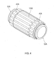
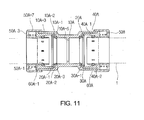
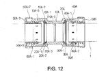
- the first body member 10A may take any of an elbow shape, a T shape, a branched shape (for allowing additional installation of pipes to the opposite lateral sides of a linear shape), etc. for diverting pipe-connecting directions besides a linear shape as shown in the drawings.
- the support member 30A is formed from a synthetic resin material or a metallic material, and has a ring shape formed with a compression groove 30A-1 that comes into tight contact with the compression ring portion 20A-1.
- the first body member 10A may be divided into two halves with reference to its central part, and the divided halves of the first body member 10A may be interconnected by a corrugated tube 80A, the opposite ends of which are embedded, through an insert-molding process, in the divided halves of the first body member 10A, respectively.
- a corrugated tube 80A the opposite ends of which are embedded, through an insert-molding process, in the divided halves of the first body member 10A, respectively.
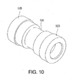
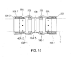
- the body member 10B includes: a pair of recessed portions 10B-1 formed by recessing the inner peripheral surface of the body member 10B; a pair of slanted surfaces 40A-1, each of which has an inner diameter increasing in the direction of inserting a pipe 1; and a pair of stopper portions 40A-2, each of which is formed at an end of the slanted surface, in which the recessed portions 10B-1, the slanted surfaces 40A-1 and the stopper portions 40A-2 are symmetrically arranged on the inner peripheral surface of the body member 10B with reference to the central part of the body member 10B in this order.
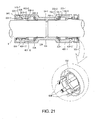
- Each first metal member 30 has a cylindrical shape and is inserted into the corresponding straight region 12-1 in a fixed state during injection molding of the main injection-molded member 10.
- the inclined surface 31 of the first metal member 30 has a diameter gradually increasing from the corresponding step 12-2 in the insertion direction of the pipe 1.
- the first metal member 30 also includes a receiving portion 32 extending from the inclined surface 31, to partially receive the corresponding fitting portion 21.
- the first metal member 30 is disposed in a region contacting the corresponding contact members 50, which are made of a metal material.
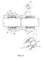
- Each third injection-molded member 10BB is threadedly coupled, at the outer circumferential surface thereof, with the corresponding enlarged portion 13AB of the first injection-molded member 10AB.
- Each third injection-molded member 10BB is provided, at an inner circumferential surface thereof, with a straight region 12-1 and a step 12-2 arranged, in this order, in a direction opposite to the insertion direction of the corresponding pipe 1.
- Each third injection-molded member 10BB is used to limit the movement range of the corresponding second injection-molded member 40, at which the contact members 50 are installed to fix the corresponding pipe 1, and to prevent separation of the second injection-molded member 40. Threaded coupling of each third injection-molded member 10BB to the first injection-molded member 10AB is irrespective of fixing of the corresponding sealing member 20.
- a cap 46 may be provided to extend along an outer end of the protrusion rib 41 to cover the third injection-molded member 10BB or main injection-molded member 10.
- the ring portion 21E is inserted in the securing recess 10-1E, thereby keeping the rubber packing member 20E from deviating from the synthetic resin body member 10E, and upon insertion of the pipe 1 the wing portion 22E is flexed in the direction of insertion of the pipe to be fitted in a gap between the pipe 1 and the synthetic resin body member 10E, and upon application of water pressure in a direction of extraction of the pipe 1, the ring portion 21E and the wing portion 22E each function to prevent the water leakage, whereby the water-tightness is ensured for connection between pipes for delivery of fluid.
- the release member 30E is basically in the form of a through cylinder and has a protruded rib 31E at its outer end and a pressing spring 30-1E is disposed between the protruded rib 31E and the stepped recess 12-1E of the synthetic resin body member 10E.
- a space for movement of the release member 30E is also utilized for disposition of the pressing spring 30-1E, as a result the entire length of the pipe connection device according to the present invention of the present invention can be shortened when compared to the case where the pressing spring 30-1E is disposed inside the synthetic resin body member 10E.
- the movement-limiting protrusions 12-21E may be directly positioned in the insertion recesses 34E, as described above, but in such a case, a work may be somewhat troublesome of pushing the release member 30E into the synthetic resin body member 10E and at the same time positioning the movement-limiting protrusions 12-21E in the insertion recesses 34E.
- the release member 30E with the pressing members 40E installed thereon When the release member 30E with the pressing members 40E installed thereon is pushed into the synthetic resin body member 10E, the movement-limiting protrusions 12-21E pass along the thickness-reduced parts 35E and when a distance between the insertion recess 34E and the movement-limiting protrusion 12-21E is shortest, the release member 30E is rotated and accordingly the movement-limiting protrusion 12-21E rides over the sliding surface 36E between the thickness-reduced part 35E and the insertion recess 34E to be easily positioned in the insertion recess 34E, whereby the release member 30E and the pressing members 40E can be prevented from deviating from the synthetic resin body member 10E.
- a insertion-limiting rib 14E for allowing the pipe 1 to be inserted by the same length from both sides is provided on the inner surface of the synthetic resin body member 10E, so that the pipe 1 is inserted only by a fixed length, as a result the pipes disposed on the both sides of the synthetic resin body member 10E can be secured over the same length.
Landscapes
- Engineering & Computer Science (AREA)
- General Engineering & Computer Science (AREA)
- Mechanical Engineering (AREA)
- Quick-Acting Or Multi-Walled Pipe Joints (AREA)
- Joints With Sleeves (AREA)
Applications Claiming Priority (6)
| Application Number | Priority Date | Filing Date | Title |
|---|---|---|---|
| KR1020110089164A KR101274094B1 (ko) | 2011-09-02 | 2011-09-02 | 원터치식 배관 연결장치 |
| KR1020110115035A KR20130049957A (ko) | 2011-11-07 | 2011-11-07 | 원터치식 배관 연결장치 |
| KR1020110140244A KR20130072705A (ko) | 2011-12-22 | 2011-12-22 | 원터치식 배관 연결장치 |
| KR1020120046100A KR20130123016A (ko) | 2012-05-02 | 2012-05-02 | 원터치식 배관 연결장치 |
| KR1020120088124A KR20140021845A (ko) | 2012-08-13 | 2012-08-13 | 원터치식 배관 연결장치 |
| PCT/KR2012/006961 WO2013032254A2 (ko) | 2011-09-02 | 2012-08-31 | 원터치식 배관 연결장치 |
Publications (2)
| Publication Number | Publication Date |
|---|---|
| EP2589848A2 true EP2589848A2 (de) | 2013-05-08 |
| EP2589848A4 EP2589848A4 (de) | 2015-05-27 |
Family
ID=47291645
Family Applications (1)
| Application Number | Title | Priority Date | Filing Date |
|---|---|---|---|
| EP12772185.0A Withdrawn EP2589848A4 (de) | 2011-09-02 | 2012-08-31 | One-touch-rohrverbindungsvorrichtung |
Country Status (6)
| Country | Link |
|---|---|
| EP (1) | EP2589848A4 (de) |
| JP (1) | JP5438869B2 (de) |
| CN (1) | CN103282714A (de) |
| AU (1) | AU2012244266A1 (de) |
| CA (1) | CA2788519A1 (de) |
| WO (1) | WO2013032254A2 (de) |
Cited By (7)
| Publication number | Priority date | Publication date | Assignee | Title |
|---|---|---|---|---|
| CN106321966A (zh) * | 2016-08-30 | 2017-01-11 | 山东胜伟园林科技有限公司 | 一种便于安装的集水管道 |
| CN106499898A (zh) * | 2016-12-27 | 2017-03-15 | 利欧集团浙江泵业有限公司 | 一种快换接头 |
| EP3060839A4 (de) * | 2013-10-24 | 2017-05-31 | Swagelok Company | Einzelachsenverschiebung zur verbindung von leitungsanschlüssen |
| US9958100B2 (en) | 2010-10-15 | 2018-05-01 | Swagelok Company | Push to connect conduit fitting with ferrule |
| US10458582B2 (en) | 2015-04-23 | 2019-10-29 | Swagelok Company | Single action push to connect conduit fitting with colleting |
| US10704722B2 (en) | 2015-04-23 | 2020-07-07 | Swagellok Company | Single action push to connect conduit fitting |
| US11781688B2 (en) | 2019-04-01 | 2023-10-10 | Swagelok Company | Push to connect conduit fitting assemblies and arrangements |
Families Citing this family (17)
| Publication number | Priority date | Publication date | Assignee | Title |
|---|---|---|---|---|
| US9360140B2 (en) * | 2013-12-10 | 2016-06-07 | GM Global Technology Operations LLC | Sealing device for a vehicle |
| WO2018157994A1 (en) * | 2017-03-01 | 2018-09-07 | Husqvarna Ab | Quick connector |
| US10400929B2 (en) * | 2017-09-27 | 2019-09-03 | Quick Fitting, Inc. | Fitting device, arrangement and method |
| CN109373071A (zh) * | 2018-11-07 | 2019-02-22 | 广州达意隆包装机械股份有限公司 | 一种柔性接头及具有柔性接头的管道 |
| US11466537B2 (en) * | 2020-03-06 | 2022-10-11 | Baker Hughes Oilfield Operations Llc | Mechanical stepper |
| AT523394B1 (de) * | 2020-06-25 | 2021-08-15 | Henn Gmbh & Co Kg | Kopplungsverfahren von Steckverbindern zu einer Steckerbaugruppe und Steckerbaugruppe |
| CN111758530B (zh) * | 2020-08-05 | 2022-02-15 | 戈传全 | 一种应用于农业灌溉的负压调节装置 |
| CN112245668B (zh) * | 2020-10-16 | 2023-01-31 | 台州学院 | 一种医用负压吸引管连接装置 |
| CN113276666A (zh) * | 2021-06-25 | 2021-08-20 | 江西昌河汽车有限责任公司 | 一种加油口颈内置的货车油箱 |
| CN113653873A (zh) * | 2021-08-24 | 2021-11-16 | 台州威思机械设备有限公司 | 一种便捷式快速接头 |
| KR102601458B1 (ko) * | 2021-11-24 | 2023-11-10 | 조현상 | 파이프 연결용 소켓 조인트 |
| CN114251530A (zh) * | 2021-12-25 | 2022-03-29 | 唐凯璇 | 一种快插式管接头 |
| JP7491595B2 (ja) * | 2022-04-15 | 2024-05-28 | 株式会社トヨックス | 管継手及び管継手に用いられるスリーブ |
| KR102521880B1 (ko) * | 2022-06-10 | 2023-04-14 | 주식회사 제이케이앤산업 | 분기배관 |
| CN116538364A (zh) * | 2023-04-07 | 2023-08-04 | 乐清市赛德斯气动有限公司 | 一种适用于气动快插接头的卡爪机构 |
| CN117307584A (zh) * | 2023-09-21 | 2023-12-29 | 江苏永昊高强度螺栓有限公司 | 一种航空发动机燃烧室前支撑螺栓紧固结构 |
| US12553548B2 (en) | 2023-11-01 | 2026-02-17 | Coupler Solutions, Llc | Conduit coupler and methods of use thereof |
Family Cites Families (15)
| Publication number | Priority date | Publication date | Assignee | Title |
|---|---|---|---|---|
| JP3372886B2 (ja) * | 1999-02-18 | 2003-02-04 | エスエムシー株式会社 | 管継手 |
| CN2540543Y (zh) * | 2002-05-27 | 2003-03-19 | 陈贞华 | 具有承插式快速接头的管件 |
| GB0227325D0 (en) * | 2002-11-22 | 2002-12-31 | Polypipe Building Products Ltd | A pipe coupling |
| KR20040062712A (ko) * | 2003-01-03 | 2004-07-09 | 아시아리드 주식회사 | 배관 연결구의 원터치식 배관 고정장치 |
| US7293758B2 (en) * | 2006-03-10 | 2007-11-13 | Lai Chang Hsueh-Feng | Pipe connector |
| KR20090132072A (ko) * | 2008-06-20 | 2009-12-30 | 김승현 | 원터치식 파이프 연결구 |
| WO2010013339A1 (ja) * | 2008-07-31 | 2010-02-04 | オーエヌ工業株式会社 | 配管のワンタッチ継手 |
| KR100899461B1 (ko) | 2009-02-27 | 2009-05-26 | 김성훈 | 다용도 플랜지 배관 연결 장치 |
| KR100927198B1 (ko) | 2009-07-16 | 2009-11-18 | 김성훈 | 다용도 플랜지 배관 연결 장치 |
| KR20110047448A (ko) * | 2009-10-30 | 2011-05-09 | 주식회사 조인탑 | 원터치 삽입식 파이프 연결 장치 |
| CN201606608U (zh) * | 2009-11-05 | 2010-10-13 | 玉环县林波铜业制品厂 | 快速接头 |
| KR100977308B1 (ko) * | 2010-02-18 | 2010-08-23 | 김성훈 | 원터치식 배관 연결장치 |
| CA2797176C (en) * | 2010-02-18 | 2015-01-06 | Sung-Hun Kim | One-touch pipe connection device |
| KR101007546B1 (ko) * | 2010-10-15 | 2011-01-14 | (주)럭키텍 | 이음관 내부에 구성되는 파이프 연결구 |
| KR101073898B1 (ko) * | 2011-07-21 | 2011-10-17 | 고용민 | 인장력 증대 및 체결이 용이한 원터치 삽입식 파이프 연결장치 |
-
2012
- 2012-08-31 WO PCT/KR2012/006961 patent/WO2013032254A2/ko not_active Ceased
- 2012-08-31 AU AU2012244266A patent/AU2012244266A1/en not_active Abandoned
- 2012-08-31 CN CN2012800012012A patent/CN103282714A/zh active Pending
- 2012-08-31 JP JP2013531519A patent/JP5438869B2/ja not_active Expired - Fee Related
- 2012-08-31 EP EP12772185.0A patent/EP2589848A4/de not_active Withdrawn
- 2012-09-04 CA CA2788519A patent/CA2788519A1/en not_active Abandoned
Cited By (14)
| Publication number | Priority date | Publication date | Assignee | Title |
|---|---|---|---|---|
| US10584820B2 (en) | 2010-10-15 | 2020-03-10 | Swagelok Company | Push to connect conduit fitting with ferrule |
| US11002395B2 (en) | 2010-10-15 | 2021-05-11 | Swagelok Company | Push to connect conduit fitting with ferrule |
| US9958100B2 (en) | 2010-10-15 | 2018-05-01 | Swagelok Company | Push to connect conduit fitting with ferrule |
| EP3060839A4 (de) * | 2013-10-24 | 2017-05-31 | Swagelok Company | Einzelachsenverschiebung zur verbindung von leitungsanschlüssen |
| US9903518B2 (en) | 2013-10-24 | 2018-02-27 | Swagelok Company | Single action push to connect conduit fitting |
| US10619780B2 (en) | 2013-10-24 | 2020-04-14 | Swagelok Company | Single action push to connect conduit fitting |
| US10458582B2 (en) | 2015-04-23 | 2019-10-29 | Swagelok Company | Single action push to connect conduit fitting with colleting |
| US10704722B2 (en) | 2015-04-23 | 2020-07-07 | Swagellok Company | Single action push to connect conduit fitting |
| US11073234B2 (en) | 2015-04-23 | 2021-07-27 | Swagelok Company | Single action push to connect conduit fitting |
| CN106321966A (zh) * | 2016-08-30 | 2017-01-11 | 山东胜伟园林科技有限公司 | 一种便于安装的集水管道 |
| CN106321966B (zh) * | 2016-08-30 | 2018-11-27 | 山东胜伟盐碱地科技有限公司 | 一种便于安装的集水管道 |
| CN106499898A (zh) * | 2016-12-27 | 2017-03-15 | 利欧集团浙江泵业有限公司 | 一种快换接头 |
| US11781688B2 (en) | 2019-04-01 | 2023-10-10 | Swagelok Company | Push to connect conduit fitting assemblies and arrangements |
| US12435820B2 (en) | 2019-04-01 | 2025-10-07 | Swagelok Company | Push to connect conduit fitting assemblies and arrangements |
Also Published As
| Publication number | Publication date |
|---|---|
| AU2012244266A1 (en) | 2013-03-14 |
| JP5438869B2 (ja) | 2014-03-12 |
| WO2013032254A3 (ko) | 2013-06-13 |
| WO2013032254A2 (ko) | 2013-03-07 |
| CN103282714A (zh) | 2013-09-04 |
| EP2589848A4 (de) | 2015-05-27 |
| CA2788519A1 (en) | 2012-12-08 |
| JP2013542378A (ja) | 2013-11-21 |
Similar Documents
| Publication | Publication Date | Title |
|---|---|---|
| EP2589848A2 (de) | One-touch-rohrverbindungsvorrichtung | |
| US11976757B2 (en) | Pre-assembled coupling assembly with cap | |
| AU2019200142B2 (en) | Split ring coupling | |
| US12049967B2 (en) | Pipe couplings | |
| US11519534B2 (en) | Split ring coupling and fitting | |
| US20130056976A1 (en) | One-touch pipe connection device | |
| EP3124846B1 (de) | Anschlussstück zur verbindung von rohrelementen | |
| US7537248B2 (en) | Combination seal and restraint system for plastic pipe | |
| KR101274094B1 (ko) | 원터치식 배관 연결장치 | |
| KR101329279B1 (ko) | 파이프 연결구조 및 파이프 연결방법 | |
| KR101186550B1 (ko) | 관이음 조립체 | |
| HK1228488A1 (en) | Split ring coupling | |
| KR20140021845A (ko) | 원터치식 배관 연결장치 |
Legal Events
| Date | Code | Title | Description |
|---|---|---|---|
| PUAI | Public reference made under article 153(3) epc to a published international application that has entered the european phase |
Free format text: ORIGINAL CODE: 0009012 |
|
| 17P | Request for examination filed |
Effective date: 20121023 |
|
| AK | Designated contracting states |
Kind code of ref document: A2 Designated state(s): AL AT BE BG CH CY CZ DE DK EE ES FI FR GB GR HR HU IE IS IT LI LT LU LV MC MK MT NL NO PL PT RO RS SE SI SK SM TR |
|
| R17D | Deferred search report published (corrected) |
Effective date: 20130613 |
|
| RIN1 | Information on inventor provided before grant (corrected) |
Inventor name: KIM, SUNG-HUN |
|
| RAP1 | Party data changed (applicant data changed or rights of an application transferred) |
Owner name: WATER-TAKE CO., LTD |
|
| DAX | Request for extension of the european patent (deleted) | ||
| STAA | Information on the status of an ep patent application or granted ep patent |
Free format text: STATUS: THE APPLICATION HAS BEEN WITHDRAWN |
|
| 18W | Application withdrawn |
Effective date: 20150421 |
|
| A4 | Supplementary search report drawn up and despatched |
Effective date: 20150423 |
|
| RIC1 | Information provided on ipc code assigned before grant |
Ipc: F16L 37/086 20060101AFI20150417BHEP Ipc: F16L 37/12 20060101ALI20150417BHEP Ipc: F16L 37/092 20060101ALI20150417BHEP |