EP2589866A2 - Injecteurs à air comprimé pour injection multipoint et procédés d'assemblage - Google Patents
Injecteurs à air comprimé pour injection multipoint et procédés d'assemblage Download PDFInfo
- Publication number
- EP2589866A2 EP2589866A2 EP12191139.0A EP12191139A EP2589866A2 EP 2589866 A2 EP2589866 A2 EP 2589866A2 EP 12191139 A EP12191139 A EP 12191139A EP 2589866 A2 EP2589866 A2 EP 2589866A2
- Authority
- EP
- European Patent Office
- Prior art keywords
- fluid
- fuel
- injector
- distributor
- conical surface
- Prior art date
- Legal status (The legal status is an assumption and is not a legal conclusion. Google has not performed a legal analysis and makes no representation as to the accuracy of the status listed.)
- Granted
Links
Images


Classifications
-
- F—MECHANICAL ENGINEERING; LIGHTING; HEATING; WEAPONS; BLASTING
- F23—COMBUSTION APPARATUS; COMBUSTION PROCESSES
- F23D—BURNERS
- F23D11/00—Burners using a direct spraying action of liquid droplets or vaporised liquid into the combustion space
- F23D11/10—Burners using a direct spraying action of liquid droplets or vaporised liquid into the combustion space the spraying being induced by a gaseous medium, e.g. water vapour
- F23D11/106—Burners using a direct spraying action of liquid droplets or vaporised liquid into the combustion space the spraying being induced by a gaseous medium, e.g. water vapour medium and fuel meeting at the burner outlet
- F23D11/107—Burners using a direct spraying action of liquid droplets or vaporised liquid into the combustion space the spraying being induced by a gaseous medium, e.g. water vapour medium and fuel meeting at the burner outlet at least one of both being subjected to a swirling motion
-
- F—MECHANICAL ENGINEERING; LIGHTING; HEATING; WEAPONS; BLASTING
- F23—COMBUSTION APPARATUS; COMBUSTION PROCESSES
- F23R—GENERATING COMBUSTION PRODUCTS OF HIGH PRESSURE OR HIGH VELOCITY, e.g. GAS-TURBINE COMBUSTION CHAMBERS
- F23R3/00—Continuous combustion chambers using liquid or gaseous fuel
- F23R3/02—Continuous combustion chambers using liquid or gaseous fuel characterised by the air-flow or gas-flow configuration
- F23R3/16—Continuous combustion chambers using liquid or gaseous fuel characterised by the air-flow or gas-flow configuration with devices inside the flame tube or the combustion chamber to influence the air or gas flow
-
- F—MECHANICAL ENGINEERING; LIGHTING; HEATING; WEAPONS; BLASTING
- F23—COMBUSTION APPARATUS; COMBUSTION PROCESSES
- F23R—GENERATING COMBUSTION PRODUCTS OF HIGH PRESSURE OR HIGH VELOCITY, e.g. GAS-TURBINE COMBUSTION CHAMBERS
- F23R3/00—Continuous combustion chambers using liquid or gaseous fuel
- F23R3/28—Continuous combustion chambers using liquid or gaseous fuel characterised by the fuel supply
-
- F—MECHANICAL ENGINEERING; LIGHTING; HEATING; WEAPONS; BLASTING
- F23—COMBUSTION APPARATUS; COMBUSTION PROCESSES
- F23D—BURNERS
- F23D2900/00—Special features of, or arrangements for burners using fluid fuels or solid fuels suspended in a carrier gas
- F23D2900/11101—Pulverising gas flow impinging on fuel from pre-filming surface, e.g. lip atomizers
-
- Y—GENERAL TAGGING OF NEW TECHNOLOGICAL DEVELOPMENTS; GENERAL TAGGING OF CROSS-SECTIONAL TECHNOLOGIES SPANNING OVER SEVERAL SECTIONS OF THE IPC; TECHNICAL SUBJECTS COVERED BY FORMER USPC CROSS-REFERENCE ART COLLECTIONS [XRACs] AND DIGESTS
- Y10—TECHNICAL SUBJECTS COVERED BY FORMER USPC
- Y10T—TECHNICAL SUBJECTS COVERED BY FORMER US CLASSIFICATION
- Y10T29/00—Metal working
- Y10T29/49—Method of mechanical manufacture
- Y10T29/49428—Gas and water specific plumbing component making
- Y10T29/49432—Nozzle making
Definitions
- the present invention relates to airblast injection nozzles, and more particularly, to systems and methods for assembling components of airblast injection nozzles for multipoint injection.
- Multipoint lean direct injection for gas turbine engines is well known in the art.
- Multipoint refers to the use of a large number of small airblast injector nozzles to introduce the fuel and air into the combustor.
- By using many very small airblast injector nozzles there is a reduction of the flow to individual nozzles, therein reducing the diameter of the nozzle.
- the volume of recirculation zone downstream of the nozzle is thought to be a controlling parameter for the quantity of NO x produced in a typical combustor.
- a larger nozzle will produce greater fuel flow, but also a greater emission index of NO X (EINO X ).
- conventional construction of small sized injectors, nozzles, atomizers and the like includes components bonding together with braze.
- the components have milled slots or drilled holes to control the flow of fuel and prepare the fuel for atomization.
- the components are typically nested within one another and form a narrow diametric gap which is filled with a braze alloy.
- the braze alloy is applied as a braze paste, wire ring, or as a thin sheet shim on the external surfaces or within pockets inside the assembly. The assembly is then heated and the braze alloy melts and flows into the narrow diametric gap and securely bonds the components together upon cooling.
- braze alloy When using traditional brazing techniques, the braze alloy must flow from a ring or pocket to the braze area. In doing so, it is prone to flow imprecisely when melted. It is also not uncommon for braze fillets to be formed on or in certain features. In some instances intricate or narrow passages can become plugged if too much braze is used. These fillets and plugs can negatively affect nozzle performance. There is higher chance fillet formation of and plugs as the nozzle components become smaller, as in multipoint applications. The difficulties in controlling braze flow employing traditional brazing techniques is a limiting factor in the design of fuel and air flow passages. That is, the shape and size of the passages is limited by the ability to control the flow of braze.
- the subject invention is directed to a new and useful method of assembling an airblast injector.
- the method includes forming a fluid passage on an internal conical surface of a first nozzle component and/or on an outer conical surface of a second nozzle component configured and adapted to mate with the first nozzle component to form at least a portion of a fluid circuit therebetween.
- the fluid passage is configured and adapted to provide passage for fluid in the fluid circuit between the first and second nozzle components.
- the method further includes joining the first and second nozzle components together by engaging the second nozzle component within the first nozzle component.
- the step of joining can include engaging the second nozzle component into the first nozzle component in an interference fit. It is also possible for the step of forming a fluid passage to include forming a thread around at least a portion the internal conical surface of the first nozzle component and/or the outer conical surface of the second nozzle component. In addition, the step of forming a fluid passage can include forming a multiple-start thread around at least a portion of the internal conical surface of the first nozzle component and/or the outer conical surface of the second nozzle component for providing multiple individual outlets for the fluid circuit. It is also possible for the method to include a step of applying braze directly to the joint location on at least one of the first and second nozzle components. The method can also include a step of applying heat to the braze to form a braze joint at the joint location. The method can also include a step of welding the first and second nozzle components together at the joint location to form a weld joint.
- the invention also provides an injector comprising a fuel distributor with a fluid inlet, and a fluid outlet.
- a fluid circuit is provided for fluid communication between the fluid inlet and the fluid outlet and includes a passage defined along a cone.
- the fuel distributor can include an outer distributor ring and an inner distributor ring mounted within the outer distributor ring.
- the fluid circuit can be formed between the inner and outer distributor rings.
- the outer distributor ring can include an internal conical surface with a helically threaded fluid passage defined therein.
- the fluid circuit can be defined between the helically threaded fluid passage of the internal conical surface of the outer distributor ring and an outer conical surface of the inner distributor ring.
- the internal conical surface of the outer distributor ring can include a multiple-start helically threaded fluid passage defined therein, wherein the fluid circuit is defined between the multiple-start helically threaded fluid passage of the internal conical surface of the outer distributor ring and an outer conical surface of the inner distributor ring.
- the fuel distributor can also include a braze or a weld joint mounting the inner and outer distributor rings together.
- the braze or weld joint bounds the fluid circuit for confining fluid flowing therethrough.
- the invention also provides an injector for use in a multipoint fuel injection system.
- the injector includes first and second nozzle components, assembled as described above, to form a fuel distributor.
- the injector includes an inner heat shield mounted inboard of the second nozzle component for thermal isolation of fuel in the fuel distributor from compressor discharge air inboard of the inner heat shield.
- the injector further includes a core air swirler mounted inboard of the inner heat shield for swirling compressor discharge air inboard of the fuel distributor for atomizing fuel issued from the fuel distributor.
- the injector includes an outer heat shield assembly mounted outboard of the first nozzle component for thermal isolation of fuel in the fuel distributor from compressor discharge air outboard of the fuel distributor.
- the outer heat shield assembly can define an outer air circuit configured and adapted to issue compressor discharge air outboard of fuel issued from the fuel distributor.
- the outer air circuit can be configured and adapted to issue a swirl-free flow of air therethrough. It is also contemplated that, the outer air circuit can be configured and adapted to issue a converging flow of air therethrough to enhance swirl imparted on a flow of compressor discharge air issued from the core air swirler.
- Airblast injector is adapted and configured for delivering fuel to the combustion chamber of a gas turbine engine.
- Nozzles used in conventional multipoint LDI configurations were pressure atomizing air assist nozzles.
- the conventional pressure atomizing air assist nozzles were generally inexpensive and light weight. In such conventional LDI configurations, it was found that the air assist nozzles had to be very small in order to allow a very large number of nozzles, for example nozzles in excess of 1000, in order to achieve the target low NO x emissions.
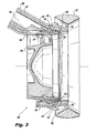
- the invention provides an injector 100 for use in a multipoint fuel injection system.
- Injector 100 includes first and second nozzle components, shown as outer and inner distributor rings 102 and 104, respectively, to form a fuel distributor 106.
- Injector 100 includes an inner heat shield 108 mounted inboard of inner distributor ring 104 for thermal isolation of fuel, as shown in Fig. 4 , in fuel distributor 106 from compressor discharge air inboard of inner heat shield 108.
- Injector 100 further includes a core air swirler 109 mounted inboard of inner heat shield 108 for swirling compressor discharge air inboard of fuel distributor 106 for atomizing fuel issued from fuel distributor 106.
- injector 100 includes an outer heat shield assembly 112 mounted outboard of first nozzle component 102 for thermal isolation of fuel in fuel distributor 106 from compressor discharge air outboard of fuel distributor 106.
- outer heat shield assembly 112 allows injector 100 to be rotated to avoid spraying fluid on adjacent walls while still permitting sealing thereof within a cylindrical sealing feature to permit axial travel during thermal growth and contraction of the combustor.
- outer heat shield assembly 112 defines an outer air circuit 114 configured and adapted to issue compressor discharge air outboard of fuel issued from fuel distributor 106.
- Outer air circuit 114 is configured and adapted to issue a swirl-free flow of air therethrough. Since outer air circuit 114 converges toward the central axis, outer air circuit 114 issues a converging flow of air therethrough to enhance swirl imparted on a flow of compressor discharge air issued from core air swirler 109.
- fuel distributor 106 includes a fluid inlet 116, and fluid outlet 118, and a fluid circuit 120.
- Fluid circuit 120 is for fluid communication between fluid inlet 116 and fluid outlet 118 and includes a three-start helically threaded fluid passage 128, defined along a cone, i.e. internal conical surface 125 of outer distributor ring 102.
- Fluid circuit 120 is defined between three-start helically threaded fluid passage 128 of internal conical surface 125 of outer distributor ring 102 and an outer conical surface 127 of inner distributor ring 104.
- the passage can be any suitable number of starts for a given application. Typically, it is contemplated that one start should be provided for every 1-inch (2.54 cm) or circumference of the passage, however, any other suitable spacing can be used without departing from the scope of the invention.
- the multiple-start thread and multiple individual outlets provide enhanced performance when operating at low pressure, for example, the multiple-starts and multiple outlets of thread allow for even fuel distribution.
- the circumferential distribution of the fuel was aided by the use multiple-start threaded passages 128 because their inherent flow resistance divided very small quantities of fuel uniformly between fluid circuit 120.
- the velocity of the fuel through fluid circuit 120 was substantially higher than it would be in a conventional airblast nozzle without threads 132.
- High velocity and fluid friction increase fuel cooling ability and helps to keep the metallic walls temperature adjacent to threads 132 cool without overheating the fuel. Therefore, permitting the multiple-start threaded passages 128 maintain an extremely small wetted surface area of the nozzle as compared to conventional airblast nozzles. The smaller the wetted surface of the nozzle, the less coke contamination occurs.
- the use of the multiple-start threaded passage along a conical surface i.e. internal conical surface 125 and/or outer conical surface 127, reduces the profile of wetted components and thus permits more space for air through the interior of the nozzle.
- the geometry of the multiple-start threaded passages 128 inherently imparts high degrees of swirl to the exiting fuel.
- the fuel flows nearly circumferentially at the exit 118 of the threads 132 and forms a uniform film on a short downstream lip of the nozzle. Intensely co-swirling air helps distribute the fuel circumferentially while it progresses to the final exit.
- the fuel film helps keep the short filming lip cool as it intervenes between the lip and the hot core air.
- fuel distributor 106 also includes a braze joint 130 mounting together inner and outer distributor rings, 104 and 102. Braze joint 130 bounds fluid circuit 120 for confining fluid flowing therethrough. Since distributor 106 includes multiple-start helically threaded fluid passages 128, braze joint 130 bounds fluid circuit 120 for confining fluid flowing therethrough.
- the method includes forming a fluid passage, i.e. multiple start helically threaded fluid passage 128, on an at least one of an internal conical surface, i.e. internal conical surface 125, of a first nozzle component, i.e. outer distributor ring 102, and an outer conical surface, i.e. outer conical surface 127, of a second nozzle component, i.e. inner distributor ring 104.
- a fluid passage i.e. multiple start helically threaded fluid passage 128, on an at least one of an internal conical surface, i.e. internal conical surface 125, of a first nozzle component, i.e. outer distributor ring 102, and an outer conical surface, i.e. outer conical surface 127, of a second nozzle component, i.e. inner distributor ring 104.
- fluid passage 128 formed on internal conical surface 125 of outer distributor ring 102
- fluid passage 128, e.g. including a multiple-start thread as described above can be formed on outer conical surface 127 of inner distributor ring 104.
- the inner distributor ring is configured and adapted to mate with the outer distributor ring to form at least a portion of a fluid circuit, i.e. fluid circuit 120, therebetween.
- the fluid passage is configured and adapted to provide passage for fluid in the fluid circuit between the outer and inner distributor rings.
- the method further includes joining the outer and inner distributor rings together by engaging the inner distributor ring within first the nozzle component.
- Joining inner and outer distributor rings together also includes engaging the inner distributor ring into the outer distributor ring in an interference fit.
- the inner distributor ring can be engaged in an interference fit with the outer distributor ring by forcefully pulling the inner distributor ring towards the outlet of the outer distributor ring.
- an interference fit is not required, for example, the inner distributor ring can be disposed within the outer distributor ring and fixed with a weld or braze at joint 130.
- inner distributor ring can be employed to form the inner wetted surface. It can be easily slid into position from the upstream end of the nozzle. The threads are cut on an adjacent conical surface, i.e. internal conical surface 125 of outer distributor ring 102, which provides a stop for the inner distributor ring. Once the inner distributor ring is in position, it can be tacked into place at a joint location, i.e. joint location 130, while pressing against the threads. The upstream end at the joint location is then brazed or welded to keep the ring in position and to seal the fluid circuit. Those having skill in the art will readily appreciate that this permits a purely mechanical placement.
- Inner distributor ring is so short, it minimizes weight it is effectively cooled by fuel. Reducing or minimizing the wetted surface of the nozzle reduces the length of the heat shield, i.e. inner or outer heat shields 108 and 112, respectively, required to keep the wetted surface carrying components cool. It can also be appreciated that the heat shielding was functionally integrated into the components of injector 100. Inner heat shield 108 forms the shroud for inner air swirler 109 into which swirler 109 could be brazed or welded. It also forms the inside of the heat shield for the feed tube of fuel circuit 120.
- outer heat shield 112 can form the inner air shroud for outer air circuit 114.
- Both inner and outer heat shields, 108 and 112 can be configured to attach together at the back of injector 100 where an air sealing weld or braze could be located.
- the heat shields, 108 and 112 thermally encapsulate inner and outer distributor rings 104 and 102, allowing them to remain at around fuel temperature even if the air is at a much higher temperature as it arrives from the compressor. Gaps between adjacent shells permit the hot components to grow radially and axially unimpeded by the cold components. Zones where hot air can touch the fuel conveying components are reduced to an absolute minimum.
- the heat shielding is kept at a reduced weight as compared to conventional injectors. Combining functionality of heat shields 108 and 112 keep cost of the components to a minimum.
- the method also includes applying braze directly to the joint location on at least one of the outer and inner distributor rings.
- the braze is applied over tack beads between the outer and inner distributor rings at the braze location, i.e. braze joint 130. Heat is then applied to the braze to form a braze joint at the joint location.
- braze joint 130 i.e. braze joint 130.
- Heat is then applied to the braze to form a braze joint at the joint location.
Landscapes
- Engineering & Computer Science (AREA)
- Chemical & Material Sciences (AREA)
- Combustion & Propulsion (AREA)
- Mechanical Engineering (AREA)
- General Engineering & Computer Science (AREA)
- Fuel-Injection Apparatus (AREA)
Applications Claiming Priority (2)
| Application Number | Priority Date | Filing Date | Title |
|---|---|---|---|
| US201161555363P | 2011-11-03 | 2011-11-03 | |
| US13/665,568 US20140339339A1 (en) | 2011-11-03 | 2012-10-31 | Airblast injectors for multipoint injection and methods of assembly |
Publications (3)
| Publication Number | Publication Date |
|---|---|
| EP2589866A2 true EP2589866A2 (fr) | 2013-05-08 |
| EP2589866A3 EP2589866A3 (fr) | 2017-01-25 |
| EP2589866B1 EP2589866B1 (fr) | 2022-01-12 |
Family
ID=47227496
Family Applications (1)
| Application Number | Title | Priority Date | Filing Date |
|---|---|---|---|
| EP12191139.0A Active EP2589866B1 (fr) | 2011-11-03 | 2012-11-02 | Injecteurs à air comprimé pour injection multipoints |
Country Status (2)
| Country | Link |
|---|---|
| US (1) | US20140339339A1 (fr) |
| EP (1) | EP2589866B1 (fr) |
Cited By (5)
| Publication number | Priority date | Publication date | Assignee | Title |
|---|---|---|---|---|
| EP3076082A1 (fr) * | 2015-03-31 | 2016-10-05 | Delavan Inc | Buses de combustible |
| EP3156732A1 (fr) * | 2015-10-16 | 2017-04-19 | Delavan, Inc. | Injecteurs à jet porté |
| US10309651B2 (en) | 2011-11-03 | 2019-06-04 | Delavan Inc | Injectors for multipoint injection |
| US10385809B2 (en) | 2015-03-31 | 2019-08-20 | Delavan Inc. | Fuel nozzles |
| EP3553382A1 (fr) * | 2018-04-10 | 2019-10-16 | Delavan, Inc. | Injecteurs de carburant pour turbomachines ayant un tourbillonnement d'air intérieur |
Families Citing this family (12)
| Publication number | Priority date | Publication date | Assignee | Title |
|---|---|---|---|---|
| US9341373B2 (en) * | 2012-03-30 | 2016-05-17 | Solar Turbines Incorporated | Air blocker ring assembly with blocker ring protrusions |
| US9989257B2 (en) * | 2015-06-24 | 2018-06-05 | Delavan Inc | Cooling in staged fuel systems |
| US10876477B2 (en) | 2016-09-16 | 2020-12-29 | Delavan Inc | Nozzles with internal manifolding |
| US11098900B2 (en) * | 2017-07-21 | 2021-08-24 | Delavan Inc. | Fuel injectors and methods of making fuel injectors |
| US20190186742A1 (en) * | 2017-12-15 | 2019-06-20 | Delavan, Inc. | Tapered helical fuel distributor |
| US11131458B2 (en) * | 2018-04-10 | 2021-09-28 | Delavan Inc. | Fuel injectors for turbomachines |
| US11143406B2 (en) * | 2018-04-10 | 2021-10-12 | Delavan Inc. | Fuel injectors having air sealing structures |
| US11118785B2 (en) * | 2018-10-26 | 2021-09-14 | Delavan Inc. | Fuel injectors for exhaust heaters |
| US10982856B2 (en) | 2019-02-01 | 2021-04-20 | Pratt & Whitney Canada Corp. | Fuel nozzle with sleeves for thermal protection |
| GB202307701D0 (en) * | 2023-05-23 | 2023-07-05 | Rolls Royce Plc | An improved combustor apparatus |
| GB202307700D0 (en) | 2023-05-23 | 2023-07-05 | Rolls Royce Plc | An improved combustor apparatus |
| GB202307702D0 (en) | 2023-05-23 | 2023-07-05 | Rolls Royce Plc | An improved combustor apparatus |
Family Cites Families (14)
| Publication number | Priority date | Publication date | Assignee | Title |
|---|---|---|---|---|
| BE488386A (fr) * | ||||
| US3638865A (en) * | 1970-08-31 | 1972-02-01 | Gen Electric | Fuel spray nozzle |
| US3887135A (en) * | 1973-11-15 | 1975-06-03 | Shigetake Tamai | Gas-atomizing nozzle by spirally rotating gas stream |
| CH623751A5 (fr) * | 1977-12-23 | 1981-06-30 | Gema Ag | |
| US4600151A (en) * | 1982-11-23 | 1986-07-15 | Ex-Cell-O Corporation | Fuel injector assembly with water or auxiliary fuel capability |
| DE3856185D1 (de) * | 1987-12-11 | 1998-06-18 | Deutsch Zentr Luft & Raumfahrt | Dralldüse zum Zerstäuben einer Flüssigkeit |
| US6622488B2 (en) * | 2001-03-21 | 2003-09-23 | Parker-Hannifin Corporation | Pure airblast nozzle |
| US7174717B2 (en) * | 2003-12-24 | 2007-02-13 | Pratt & Whitney Canada Corp. | Helical channel fuel distributor and method |
| US7117678B2 (en) * | 2004-04-02 | 2006-10-10 | Pratt & Whitney Canada Corp. | Fuel injector head |
| US8348180B2 (en) * | 2004-06-09 | 2013-01-08 | Delavan Inc | Conical swirler for fuel injectors and combustor domes and methods of manufacturing the same |
| US7926178B2 (en) * | 2007-11-30 | 2011-04-19 | Delavan Inc | Method of fuel nozzle construction |
| US7926282B2 (en) * | 2008-03-04 | 2011-04-19 | Delavan Inc | Pure air blast fuel injector |
| US20090255258A1 (en) * | 2008-04-11 | 2009-10-15 | Delavan Inc | Pre-filming air-blast fuel injector having a reduced hydraulic spray angle |
| US8096135B2 (en) * | 2008-05-06 | 2012-01-17 | Dela Van Inc | Pure air blast fuel injector |
-
2012
- 2012-10-31 US US13/665,568 patent/US20140339339A1/en not_active Abandoned
- 2012-11-02 EP EP12191139.0A patent/EP2589866B1/fr active Active
Non-Patent Citations (1)
| Title |
|---|
| None |
Cited By (9)
| Publication number | Priority date | Publication date | Assignee | Title |
|---|---|---|---|---|
| US10309651B2 (en) | 2011-11-03 | 2019-06-04 | Delavan Inc | Injectors for multipoint injection |
| EP3076082A1 (fr) * | 2015-03-31 | 2016-10-05 | Delavan Inc | Buses de combustible |
| US9897321B2 (en) | 2015-03-31 | 2018-02-20 | Delavan Inc. | Fuel nozzles |
| US10385809B2 (en) | 2015-03-31 | 2019-08-20 | Delavan Inc. | Fuel nozzles |
| US11111888B2 (en) | 2015-03-31 | 2021-09-07 | Delavan Inc. | Fuel nozzles |
| EP3156732A1 (fr) * | 2015-10-16 | 2017-04-19 | Delavan, Inc. | Injecteurs à jet porté |
| US10132500B2 (en) | 2015-10-16 | 2018-11-20 | Delavan Inc. | Airblast injectors |
| EP3553382A1 (fr) * | 2018-04-10 | 2019-10-16 | Delavan, Inc. | Injecteurs de carburant pour turbomachines ayant un tourbillonnement d'air intérieur |
| US10788214B2 (en) | 2018-04-10 | 2020-09-29 | Delavan Inc. | Fuel injectors for turbomachines having inner air swirling |
Also Published As
| Publication number | Publication date |
|---|---|
| EP2589866A3 (fr) | 2017-01-25 |
| US20140339339A1 (en) | 2014-11-20 |
| EP2589866B1 (fr) | 2022-01-12 |
Similar Documents
| Publication | Publication Date | Title |
|---|---|---|
| EP2589866B1 (fr) | Injecteurs à air comprimé pour injection multipoints | |
| EP3156732B1 (fr) | Injecteurs de carburant par soufflage d'air | |
| US9920693B2 (en) | Hollow-wall heat shield for fuel injector component | |
| JP5762424B2 (ja) | タービンのエンジン燃焼室のための多点式燃料噴射器 | |
| EP3995742B1 (fr) | Système de refroidissement de torche d'allumage | |
| US9518742B2 (en) | Premixer assembly for mixing air and fuel for combustion | |
| GB2460101A (en) | Fuel Injector Apparatus with Brazed and Interference Fit Components, and a Method of Assembly | |
| EP3165825B1 (fr) | Injecteur de carburant réparable | |
| CA2900175C (fr) | Injecteur de carburant | |
| EP3553382B1 (fr) | Injecteurs de carburant pour turbomachines ayant un tourbillonnement d'air intérieur | |
| US20140367494A1 (en) | Additively manufactured nozzle tip for fuel injector | |
| US20160025009A1 (en) | Method of supplying fuel to an internal fuel manifold | |
| EP3995740B1 (fr) | Système de refroidissement de brûleur d'allumage | |
| US11761634B2 (en) | Fuel injector assemblies | |
| EP4286057A2 (fr) | Élément de tourbillonnement de carburant pour buses de carburant sous pression | |
| US10907832B2 (en) | Pilot nozzle tips for extended lance of combustor burner | |
| US10295186B2 (en) | Airblast nozzle with upstream fuel distribution and near-exit swirl | |
| CN103339443B (zh) | 用于涡轮发动机燃烧室的喷射系统 |
Legal Events
| Date | Code | Title | Description |
|---|---|---|---|
| PUAI | Public reference made under article 153(3) epc to a published international application that has entered the european phase |
Free format text: ORIGINAL CODE: 0009012 |
|
| 17P | Request for examination filed |
Effective date: 20121102 |
|
| AK | Designated contracting states |
Kind code of ref document: A2 Designated state(s): AL AT BE BG CH CY CZ DE DK EE ES FI FR GB GR HR HU IE IS IT LI LT LU LV MC MK MT NL NO PL PT RO RS SE SI SK SM TR |
|
| AX | Request for extension of the european patent |
Extension state: BA ME |
|
| RIN1 | Information on inventor provided before grant (corrected) |
Inventor name: PROCIW, LEV ALEXANDER Inventor name: RYON, JASON A.. |
|
| PUAL | Search report despatched |
Free format text: ORIGINAL CODE: 0009013 |
|
| AK | Designated contracting states |
Kind code of ref document: A3 Designated state(s): AL AT BE BG CH CY CZ DE DK EE ES FI FR GB GR HR HU IE IS IT LI LT LU LV MC MK MT NL NO PL PT RO RS SE SI SK SM TR |
|
| AX | Request for extension of the european patent |
Extension state: BA ME |
|
| RIC1 | Information provided on ipc code assigned before grant |
Ipc: F23D 11/10 20060101AFI20161216BHEP Ipc: F23R 3/28 20060101ALI20161216BHEP |
|
| RIN1 | Information on inventor provided before grant (corrected) |
Inventor name: PROCIW, LEV ALEXANDER Inventor name: RYON, JASON A.. |
|
| STAA | Information on the status of an ep patent application or granted ep patent |
Free format text: STATUS: EXAMINATION IS IN PROGRESS |
|
| 17Q | First examination report despatched |
Effective date: 20181212 |
|
| GRAP | Despatch of communication of intention to grant a patent |
Free format text: ORIGINAL CODE: EPIDOSNIGR1 |
|
| STAA | Information on the status of an ep patent application or granted ep patent |
Free format text: STATUS: GRANT OF PATENT IS INTENDED |
|
| RAP1 | Party data changed (applicant data changed or rights of an application transferred) |
Owner name: DELAVAN, INC. |
|
| INTG | Intention to grant announced |
Effective date: 20210127 |
|
| GRAJ | Information related to disapproval of communication of intention to grant by the applicant or resumption of examination proceedings by the epo deleted |
Free format text: ORIGINAL CODE: EPIDOSDIGR1 |
|
| STAA | Information on the status of an ep patent application or granted ep patent |
Free format text: STATUS: EXAMINATION IS IN PROGRESS |
|
| INTC | Intention to grant announced (deleted) | ||
| GRAP | Despatch of communication of intention to grant a patent |
Free format text: ORIGINAL CODE: EPIDOSNIGR1 |
|
| STAA | Information on the status of an ep patent application or granted ep patent |
Free format text: STATUS: GRANT OF PATENT IS INTENDED |
|
| INTG | Intention to grant announced |
Effective date: 20210723 |
|
| GRAS | Grant fee paid |
Free format text: ORIGINAL CODE: EPIDOSNIGR3 |
|
| GRAA | (expected) grant |
Free format text: ORIGINAL CODE: 0009210 |
|
| STAA | Information on the status of an ep patent application or granted ep patent |
Free format text: STATUS: THE PATENT HAS BEEN GRANTED |
|
| AK | Designated contracting states |
Kind code of ref document: B1 Designated state(s): AL AT BE BG CH CY CZ DE DK EE ES FI FR GB GR HR HU IE IS IT LI LT LU LV MC MK MT NL NO PL PT RO RS SE SI SK SM TR |
|
| REG | Reference to a national code |
Ref country code: GB Ref legal event code: FG4D |
|
| REG | Reference to a national code |
Ref country code: CH Ref legal event code: EP |
|
| REG | Reference to a national code |
Ref country code: DE Ref legal event code: R096 Ref document number: 602012077517 Country of ref document: DE |
|
| REG | Reference to a national code |
Ref country code: IE Ref legal event code: FG4D |
|
| REG | Reference to a national code |
Ref country code: AT Ref legal event code: REF Ref document number: 1462627 Country of ref document: AT Kind code of ref document: T Effective date: 20220215 |
|
| REG | Reference to a national code |
Ref country code: LT Ref legal event code: MG9D |
|
| RAP4 | Party data changed (patent owner data changed or rights of a patent transferred) |
Owner name: COLLINS ENGINE NOZZLES, INC. |
|
| REG | Reference to a national code |
Ref country code: NL Ref legal event code: MP Effective date: 20220112 |
|
| REG | Reference to a national code |
Ref country code: AT Ref legal event code: MK05 Ref document number: 1462627 Country of ref document: AT Kind code of ref document: T Effective date: 20220112 |
|
| PG25 | Lapsed in a contracting state [announced via postgrant information from national office to epo] |
Ref country code: NL Free format text: LAPSE BECAUSE OF FAILURE TO SUBMIT A TRANSLATION OF THE DESCRIPTION OR TO PAY THE FEE WITHIN THE PRESCRIBED TIME-LIMIT Effective date: 20220112 |
|
| PG25 | Lapsed in a contracting state [announced via postgrant information from national office to epo] |
Ref country code: SE Free format text: LAPSE BECAUSE OF FAILURE TO SUBMIT A TRANSLATION OF THE DESCRIPTION OR TO PAY THE FEE WITHIN THE PRESCRIBED TIME-LIMIT Effective date: 20220112 Ref country code: RS Free format text: LAPSE BECAUSE OF FAILURE TO SUBMIT A TRANSLATION OF THE DESCRIPTION OR TO PAY THE FEE WITHIN THE PRESCRIBED TIME-LIMIT Effective date: 20220112 Ref country code: PT Free format text: LAPSE BECAUSE OF FAILURE TO SUBMIT A TRANSLATION OF THE DESCRIPTION OR TO PAY THE FEE WITHIN THE PRESCRIBED TIME-LIMIT Effective date: 20220512 Ref country code: NO Free format text: LAPSE BECAUSE OF FAILURE TO SUBMIT A TRANSLATION OF THE DESCRIPTION OR TO PAY THE FEE WITHIN THE PRESCRIBED TIME-LIMIT Effective date: 20220412 Ref country code: LT Free format text: LAPSE BECAUSE OF FAILURE TO SUBMIT A TRANSLATION OF THE DESCRIPTION OR TO PAY THE FEE WITHIN THE PRESCRIBED TIME-LIMIT Effective date: 20220112 Ref country code: HR Free format text: LAPSE BECAUSE OF FAILURE TO SUBMIT A TRANSLATION OF THE DESCRIPTION OR TO PAY THE FEE WITHIN THE PRESCRIBED TIME-LIMIT Effective date: 20220112 Ref country code: ES Free format text: LAPSE BECAUSE OF FAILURE TO SUBMIT A TRANSLATION OF THE DESCRIPTION OR TO PAY THE FEE WITHIN THE PRESCRIBED TIME-LIMIT Effective date: 20220112 Ref country code: BG Free format text: LAPSE BECAUSE OF FAILURE TO SUBMIT A TRANSLATION OF THE DESCRIPTION OR TO PAY THE FEE WITHIN THE PRESCRIBED TIME-LIMIT Effective date: 20220412 |
|
| PG25 | Lapsed in a contracting state [announced via postgrant information from national office to epo] |
Ref country code: PL Free format text: LAPSE BECAUSE OF FAILURE TO SUBMIT A TRANSLATION OF THE DESCRIPTION OR TO PAY THE FEE WITHIN THE PRESCRIBED TIME-LIMIT Effective date: 20220112 Ref country code: LV Free format text: LAPSE BECAUSE OF FAILURE TO SUBMIT A TRANSLATION OF THE DESCRIPTION OR TO PAY THE FEE WITHIN THE PRESCRIBED TIME-LIMIT Effective date: 20220112 Ref country code: GR Free format text: LAPSE BECAUSE OF FAILURE TO SUBMIT A TRANSLATION OF THE DESCRIPTION OR TO PAY THE FEE WITHIN THE PRESCRIBED TIME-LIMIT Effective date: 20220413 Ref country code: FI Free format text: LAPSE BECAUSE OF FAILURE TO SUBMIT A TRANSLATION OF THE DESCRIPTION OR TO PAY THE FEE WITHIN THE PRESCRIBED TIME-LIMIT Effective date: 20220112 Ref country code: AT Free format text: LAPSE BECAUSE OF FAILURE TO SUBMIT A TRANSLATION OF THE DESCRIPTION OR TO PAY THE FEE WITHIN THE PRESCRIBED TIME-LIMIT Effective date: 20220112 |
|
| PG25 | Lapsed in a contracting state [announced via postgrant information from national office to epo] |
Ref country code: IS Free format text: LAPSE BECAUSE OF FAILURE TO SUBMIT A TRANSLATION OF THE DESCRIPTION OR TO PAY THE FEE WITHIN THE PRESCRIBED TIME-LIMIT Effective date: 20220512 |
|
| REG | Reference to a national code |
Ref country code: DE Ref legal event code: R097 Ref document number: 602012077517 Country of ref document: DE |
|
| PG25 | Lapsed in a contracting state [announced via postgrant information from national office to epo] |
Ref country code: SM Free format text: LAPSE BECAUSE OF FAILURE TO SUBMIT A TRANSLATION OF THE DESCRIPTION OR TO PAY THE FEE WITHIN THE PRESCRIBED TIME-LIMIT Effective date: 20220112 Ref country code: SK Free format text: LAPSE BECAUSE OF FAILURE TO SUBMIT A TRANSLATION OF THE DESCRIPTION OR TO PAY THE FEE WITHIN THE PRESCRIBED TIME-LIMIT Effective date: 20220112 Ref country code: RO Free format text: LAPSE BECAUSE OF FAILURE TO SUBMIT A TRANSLATION OF THE DESCRIPTION OR TO PAY THE FEE WITHIN THE PRESCRIBED TIME-LIMIT Effective date: 20220112 Ref country code: EE Free format text: LAPSE BECAUSE OF FAILURE TO SUBMIT A TRANSLATION OF THE DESCRIPTION OR TO PAY THE FEE WITHIN THE PRESCRIBED TIME-LIMIT Effective date: 20220112 Ref country code: DK Free format text: LAPSE BECAUSE OF FAILURE TO SUBMIT A TRANSLATION OF THE DESCRIPTION OR TO PAY THE FEE WITHIN THE PRESCRIBED TIME-LIMIT Effective date: 20220112 Ref country code: CZ Free format text: LAPSE BECAUSE OF FAILURE TO SUBMIT A TRANSLATION OF THE DESCRIPTION OR TO PAY THE FEE WITHIN THE PRESCRIBED TIME-LIMIT Effective date: 20220112 |
|
| PLBE | No opposition filed within time limit |
Free format text: ORIGINAL CODE: 0009261 |
|
| STAA | Information on the status of an ep patent application or granted ep patent |
Free format text: STATUS: NO OPPOSITION FILED WITHIN TIME LIMIT |
|
| PG25 | Lapsed in a contracting state [announced via postgrant information from national office to epo] |
Ref country code: AL Free format text: LAPSE BECAUSE OF FAILURE TO SUBMIT A TRANSLATION OF THE DESCRIPTION OR TO PAY THE FEE WITHIN THE PRESCRIBED TIME-LIMIT Effective date: 20220112 |
|
| 26N | No opposition filed |
Effective date: 20221013 |
|
| PG25 | Lapsed in a contracting state [announced via postgrant information from national office to epo] |
Ref country code: SI Free format text: LAPSE BECAUSE OF FAILURE TO SUBMIT A TRANSLATION OF THE DESCRIPTION OR TO PAY THE FEE WITHIN THE PRESCRIBED TIME-LIMIT Effective date: 20220112 |
|
| PG25 | Lapsed in a contracting state [announced via postgrant information from national office to epo] |
Ref country code: MC Free format text: LAPSE BECAUSE OF FAILURE TO SUBMIT A TRANSLATION OF THE DESCRIPTION OR TO PAY THE FEE WITHIN THE PRESCRIBED TIME-LIMIT Effective date: 20220112 |
|
| REG | Reference to a national code |
Ref country code: CH Ref legal event code: PL |
|
| P01 | Opt-out of the competence of the unified patent court (upc) registered |
Effective date: 20230530 |
|
| REG | Reference to a national code |
Ref country code: BE Ref legal event code: MM Effective date: 20221130 |
|
| PG25 | Lapsed in a contracting state [announced via postgrant information from national office to epo] |
Ref country code: LI Free format text: LAPSE BECAUSE OF NON-PAYMENT OF DUE FEES Effective date: 20221130 Ref country code: IT Free format text: LAPSE BECAUSE OF FAILURE TO SUBMIT A TRANSLATION OF THE DESCRIPTION OR TO PAY THE FEE WITHIN THE PRESCRIBED TIME-LIMIT Effective date: 20220112 Ref country code: CH Free format text: LAPSE BECAUSE OF NON-PAYMENT OF DUE FEES Effective date: 20221130 |
|
| PG25 | Lapsed in a contracting state [announced via postgrant information from national office to epo] |
Ref country code: LU Free format text: LAPSE BECAUSE OF NON-PAYMENT OF DUE FEES Effective date: 20221102 |
|
| PG25 | Lapsed in a contracting state [announced via postgrant information from national office to epo] |
Ref country code: IE Free format text: LAPSE BECAUSE OF NON-PAYMENT OF DUE FEES Effective date: 20221102 |
|
| PG25 | Lapsed in a contracting state [announced via postgrant information from national office to epo] |
Ref country code: BE Free format text: LAPSE BECAUSE OF NON-PAYMENT OF DUE FEES Effective date: 20221130 |
|
| PG25 | Lapsed in a contracting state [announced via postgrant information from national office to epo] |
Ref country code: HU Free format text: LAPSE BECAUSE OF FAILURE TO SUBMIT A TRANSLATION OF THE DESCRIPTION OR TO PAY THE FEE WITHIN THE PRESCRIBED TIME-LIMIT; INVALID AB INITIO Effective date: 20121102 |
|
| PG25 | Lapsed in a contracting state [announced via postgrant information from national office to epo] |
Ref country code: CY Free format text: LAPSE BECAUSE OF FAILURE TO SUBMIT A TRANSLATION OF THE DESCRIPTION OR TO PAY THE FEE WITHIN THE PRESCRIBED TIME-LIMIT Effective date: 20220112 |
|
| PG25 | Lapsed in a contracting state [announced via postgrant information from national office to epo] |
Ref country code: MK Free format text: LAPSE BECAUSE OF FAILURE TO SUBMIT A TRANSLATION OF THE DESCRIPTION OR TO PAY THE FEE WITHIN THE PRESCRIBED TIME-LIMIT Effective date: 20220112 |
|
| PG25 | Lapsed in a contracting state [announced via postgrant information from national office to epo] |
Ref country code: TR Free format text: LAPSE BECAUSE OF FAILURE TO SUBMIT A TRANSLATION OF THE DESCRIPTION OR TO PAY THE FEE WITHIN THE PRESCRIBED TIME-LIMIT Effective date: 20220112 |
|
| PG25 | Lapsed in a contracting state [announced via postgrant information from national office to epo] |
Ref country code: MT Free format text: LAPSE BECAUSE OF FAILURE TO SUBMIT A TRANSLATION OF THE DESCRIPTION OR TO PAY THE FEE WITHIN THE PRESCRIBED TIME-LIMIT Effective date: 20220112 |
|
| PGFP | Annual fee paid to national office [announced via postgrant information from national office to epo] |
Ref country code: DE Payment date: 20251022 Year of fee payment: 14 |
|
| PGFP | Annual fee paid to national office [announced via postgrant information from national office to epo] |
Ref country code: GB Payment date: 20251022 Year of fee payment: 14 |
|
| PGFP | Annual fee paid to national office [announced via postgrant information from national office to epo] |
Ref country code: FR Payment date: 20251022 Year of fee payment: 14 |