EP2589872A2 - Composant et turbomachine avec un tel composant - Google Patents
Composant et turbomachine avec un tel composant Download PDFInfo
- Publication number
- EP2589872A2 EP2589872A2 EP12190796.8A EP12190796A EP2589872A2 EP 2589872 A2 EP2589872 A2 EP 2589872A2 EP 12190796 A EP12190796 A EP 12190796A EP 2589872 A2 EP2589872 A2 EP 2589872A2
- Authority
- EP
- European Patent Office
- Prior art keywords
- width
- structural element
- component according
- structural
- component
- Prior art date
- Legal status (The legal status is an assumption and is not a legal conclusion. Google has not performed a legal analysis and makes no representation as to the accuracy of the status listed.)
- Granted
Links
Images


Classifications
-
- F—MECHANICAL ENGINEERING; LIGHTING; HEATING; WEAPONS; BLASTING
- F02—COMBUSTION ENGINES; HOT-GAS OR COMBUSTION-PRODUCT ENGINE PLANTS
- F02C—GAS-TURBINE PLANTS; AIR INTAKES FOR JET-PROPULSION PLANTS; CONTROLLING FUEL SUPPLY IN AIR-BREATHING JET-PROPULSION PLANTS
- F02C7/00—Features, components parts, details or accessories, not provided for in, or of interest apart form groups F02C1/00 - F02C6/00; Air intakes for jet-propulsion plants
-
- F—MECHANICAL ENGINEERING; LIGHTING; HEATING; WEAPONS; BLASTING
- F01—MACHINES OR ENGINES IN GENERAL; ENGINE PLANTS IN GENERAL; STEAM ENGINES
- F01D—NON-POSITIVE DISPLACEMENT MACHINES OR ENGINES, e.g. STEAM TURBINES
- F01D9/00—Stators
- F01D9/02—Nozzles; Nozzle boxes; Stator blades; Guide conduits, e.g. individual nozzles
- F01D9/023—Transition ducts between combustor cans and first stage of the turbine in gas-turbine engines; their cooling or sealings
-
- B—PERFORMING OPERATIONS; TRANSPORTING
- B32—LAYERED PRODUCTS
- B32B—LAYERED PRODUCTS, i.e. PRODUCTS BUILT-UP OF STRATA OF FLAT OR NON-FLAT, e.g. CELLULAR OR HONEYCOMB, FORM
- B32B3/00—Layered products comprising a layer with external or internal discontinuities or unevennesses, or a layer of non-planar shape; Layered products comprising a layer having particular features of form
- B32B3/10—Layered products comprising a layer with external or internal discontinuities or unevennesses, or a layer of non-planar shape; Layered products comprising a layer having particular features of form characterised by a discontinuous layer, i.e. formed of separate pieces of material
- B32B3/12—Layered products comprising a layer with external or internal discontinuities or unevennesses, or a layer of non-planar shape; Layered products comprising a layer having particular features of form characterised by a discontinuous layer, i.e. formed of separate pieces of material characterised by a layer of regularly- arranged cells, e.g. a honeycomb structure
-
- B—PERFORMING OPERATIONS; TRANSPORTING
- B32—LAYERED PRODUCTS
- B32B—LAYERED PRODUCTS, i.e. PRODUCTS BUILT-UP OF STRATA OF FLAT OR NON-FLAT, e.g. CELLULAR OR HONEYCOMB, FORM
- B32B3/00—Layered products comprising a layer with external or internal discontinuities or unevennesses, or a layer of non-planar shape; Layered products comprising a layer having particular features of form
- B32B3/26—Layered products comprising a layer with external or internal discontinuities or unevennesses, or a layer of non-planar shape; Layered products comprising a layer having particular features of form characterised by a particular shape of the outline of the cross-section of a continuous layer; characterised by a layer with cavities or internal voids ; characterised by an apertured layer
- B32B3/263—Layered products comprising a layer with external or internal discontinuities or unevennesses, or a layer of non-planar shape; Layered products comprising a layer having particular features of form characterised by a particular shape of the outline of the cross-section of a continuous layer; characterised by a layer with cavities or internal voids ; characterised by an apertured layer characterised by a layer having non-uniform thickness
-
- F—MECHANICAL ENGINEERING; LIGHTING; HEATING; WEAPONS; BLASTING
- F23—COMBUSTION APPARATUS; COMBUSTION PROCESSES
- F23M—CASINGS, LININGS, WALLS OR DOORS SPECIALLY ADAPTED FOR COMBUSTION CHAMBERS, e.g. FIREBRIDGES; DEVICES FOR DEFLECTING AIR, FLAMES OR COMBUSTION PRODUCTS IN COMBUSTION CHAMBERS; SAFETY ARRANGEMENTS SPECIALLY ADAPTED FOR COMBUSTION APPARATUS; DETAILS OF COMBUSTION CHAMBERS, NOT OTHERWISE PROVIDED FOR
- F23M5/00—Casings; Linings; Walls
- F23M5/04—Supports for linings
-
- F—MECHANICAL ENGINEERING; LIGHTING; HEATING; WEAPONS; BLASTING
- F23—COMBUSTION APPARATUS; COMBUSTION PROCESSES
- F23R—GENERATING COMBUSTION PRODUCTS OF HIGH PRESSURE OR HIGH VELOCITY, e.g. GAS-TURBINE COMBUSTION CHAMBERS
- F23R3/00—Continuous combustion chambers using liquid or gaseous fuel
- F23R3/002—Wall structures
-
- F—MECHANICAL ENGINEERING; LIGHTING; HEATING; WEAPONS; BLASTING
- F23—COMBUSTION APPARATUS; COMBUSTION PROCESSES
- F23M—CASINGS, LININGS, WALLS OR DOORS SPECIALLY ADAPTED FOR COMBUSTION CHAMBERS, e.g. FIREBRIDGES; DEVICES FOR DEFLECTING AIR, FLAMES OR COMBUSTION PRODUCTS IN COMBUSTION CHAMBERS; SAFETY ARRANGEMENTS SPECIALLY ADAPTED FOR COMBUSTION APPARATUS; DETAILS OF COMBUSTION CHAMBERS, NOT OTHERWISE PROVIDED FOR
- F23M2900/00—Special features of, or arrangements for combustion chambers
- F23M2900/05004—Special materials for walls or lining
-
- Y—GENERAL TAGGING OF NEW TECHNOLOGICAL DEVELOPMENTS; GENERAL TAGGING OF CROSS-SECTIONAL TECHNOLOGIES SPANNING OVER SEVERAL SECTIONS OF THE IPC; TECHNICAL SUBJECTS COVERED BY FORMER USPC CROSS-REFERENCE ART COLLECTIONS [XRACs] AND DIGESTS
- Y02—TECHNOLOGIES OR APPLICATIONS FOR MITIGATION OR ADAPTATION AGAINST CLIMATE CHANGE
- Y02T—CLIMATE CHANGE MITIGATION TECHNOLOGIES RELATED TO TRANSPORTATION
- Y02T50/00—Aeronautics or air transport
- Y02T50/60—Efficient propulsion technologies, e.g. for aircraft
-
- Y—GENERAL TAGGING OF NEW TECHNOLOGICAL DEVELOPMENTS; GENERAL TAGGING OF CROSS-SECTIONAL TECHNOLOGIES SPANNING OVER SEVERAL SECTIONS OF THE IPC; TECHNICAL SUBJECTS COVERED BY FORMER USPC CROSS-REFERENCE ART COLLECTIONS [XRACs] AND DIGESTS
- Y10—TECHNICAL SUBJECTS COVERED BY FORMER USPC
- Y10T—TECHNICAL SUBJECTS COVERED BY FORMER US CLASSIFICATION
- Y10T428/00—Stock material or miscellaneous articles
- Y10T428/24—Structurally defined web or sheet [e.g., overall dimension, etc.]
- Y10T428/24149—Honeycomb-like
-
- Y—GENERAL TAGGING OF NEW TECHNOLOGICAL DEVELOPMENTS; GENERAL TAGGING OF CROSS-SECTIONAL TECHNOLOGIES SPANNING OVER SEVERAL SECTIONS OF THE IPC; TECHNICAL SUBJECTS COVERED BY FORMER USPC CROSS-REFERENCE ART COLLECTIONS [XRACs] AND DIGESTS
- Y10—TECHNICAL SUBJECTS COVERED BY FORMER USPC
- Y10T—TECHNICAL SUBJECTS COVERED BY FORMER US CLASSIFICATION
- Y10T428/00—Stock material or miscellaneous articles
- Y10T428/24—Structurally defined web or sheet [e.g., overall dimension, etc.]
- Y10T428/24479—Structurally defined web or sheet [e.g., overall dimension, etc.] including variation in thickness
- Y10T428/24521—Structurally defined web or sheet [e.g., overall dimension, etc.] including variation in thickness with component conforming to contour of nonplanar surface
-
- Y—GENERAL TAGGING OF NEW TECHNOLOGICAL DEVELOPMENTS; GENERAL TAGGING OF CROSS-SECTIONAL TECHNOLOGIES SPANNING OVER SEVERAL SECTIONS OF THE IPC; TECHNICAL SUBJECTS COVERED BY FORMER USPC CROSS-REFERENCE ART COLLECTIONS [XRACs] AND DIGESTS
- Y10—TECHNICAL SUBJECTS COVERED BY FORMER USPC
- Y10T—TECHNICAL SUBJECTS COVERED BY FORMER US CLASSIFICATION
- Y10T428/00—Stock material or miscellaneous articles
- Y10T428/24—Structurally defined web or sheet [e.g., overall dimension, etc.]
- Y10T428/24479—Structurally defined web or sheet [e.g., overall dimension, etc.] including variation in thickness
- Y10T428/24521—Structurally defined web or sheet [e.g., overall dimension, etc.] including variation in thickness with component conforming to contour of nonplanar surface
- Y10T428/24545—Containing metal or metal compound
Definitions
- the invention relates to a component for use in a turbomachine and a turbomachine with this component.
- turbomachinery such as. As aircraft engines or stationary steam or gas turbines, very high operating temperatures are reached during operation. In modern aircraft engines z. B. to over 2,000 K can be achieved. As a result, certain parts of the turbomachine, such. B. combustion chambers or the input area of the turbine in an aircraft engine, subjected to very high thermal loads. Furthermore, these components must additionally withstand high mechanical loads, in particular when starting up a turbine, since the tips of the turbine blades come into contact with the turbine wall at least in the short term.
- a base of a component has at least one structural element for connection to the high-temperature coating, the cross-section of the at least one structural element having at least three different widths, namely a base width at the lower end of the at least one structural element, an overlying center width and an overlying peak width Means the center width is greater than or equal to the basic width, but less than four times the basic width, but in particular smaller than or equal to the triple base width.
- the shaping achieves an undercut that is deep enough for secure anchoring of the high temperature coating, but not too deep to allow for safe filling of the undercut.
- the base width and / or the center width and the tip width is less than or equal to the height of the at least one structural element measured from the lower end of the at least one structural element.
- a height limit limits the influence on the surface modification.
- the peak width of the at least one structural element is smaller than the central width, an upwardly narrowing structure is achieved. This has the advantage that it can generate targeted vertical cracks in the high-temperature coating, which can lead to stress relief.
- a further advantageous embodiment has at least one structural element which, measured from the lower end to the tip, has an average height of between 100 and 500 ⁇ m. It is also advantageous if, on average, the center width and the peak width of the structural element are less than or equal to the height of the structural element.
- the base of the device is not excessively influenced if the at least one structural element has on average a basic width of more than 30 ⁇ m, and less than 500 ⁇ m.
- the center width and / or the tip width of the at least one structural element is on average smaller than the height of the at least one structural element.
- the structural elements are combined into structural patterns.
- a structural pattern has at least two structural elements, wherein the at least two structural elements intersect or are arranged parallel to one another. It is particularly advantageous if the structural pattern has the form of a grid, a network structure, a honeycomb structure or a wave structure of shafts running parallel to one another.
- a good prevention of unwanted cracks results in embodiments in which the distance between two parallel sections of two structural elements between 500 and 5000 microns.
- the at least one structural element has a linear structure or curve-like structure with an average width of 100 to 400 ⁇ m at the widest point (in particular the center width).
- flanks converge on average at an angle which is less than 180 °, in particular less than 120 °, very particularly less than or equal to 90 °.
- tips are formed upwards, which are useful for the generation of vertical cracks 12.
- turbomachine in particular aircraft engine having the features of claim 13.
- At least one component according to at least one of claims 1 to 12, in particular in a combustion chamber, is arranged on the wall of the turbine and / or in the inlet region of the high-pressure part of a turbine.
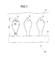
- Figure 11 is a sectional view through part of a component 10 which is particularly adapted to be used in high temperature areas of turbomachinery.
- the component 10 itself has, in the illustrated embodiment, a base 11 made of a metallic material.
- the at least one structural element 1 arranged on the base 11 can be produced both from metallic or ceramic material and from a mixture of the two.
- a high temperature coating 2 e.g. of an oxide ceramic, in particular containing yttrium, zirconium, zirconium oxide, magnesium spinel and / or aluminum oxide.
- an oxide ceramic in particular containing yttrium, zirconium, zirconium oxide, magnesium spinel and / or aluminum oxide.
- YSZ Yittrium stabilized zirconia
- the base has a number of structural elements 1, which are formed in a special way. In the exemplary embodiment illustrated here, three parallel, substantially uniform structural elements 1 are shown.
- the structural elements 1 extend into the plane of the drawing and are, for example, linearly constructed at least in sections (see, for example, FIG Fig. 2A ).
- the structural elements 1 in the embodiment shown here are integrally formed with the base 11, ie they are constructed of the same material. In other embodiments, the structural elements 1 may also be made of a different material than the base 11.
- the structural elements 1 with the undercuts can e.g. by an isotropic etching process, electrochemical ablation, and / or a generative laser process, e.g. Laser deposition welding are produced.
- One possible etching method for the above-mentioned materials uses e.g. a mixture of an aqueous iron (III) chloride solution, hydrochloric acid and nitric acid.
- the etching should be carried out in the boiling state.
- cobalt-containing materials e.g. a mixture of distilled water and nitric acid, a mixture of hydrochloric acid, nitric acid and ferric chloride, or a mixture of distilled water, hydrochloric acid and cupric sulfate.
- the structural elements 1 have a height h between 100 ⁇ m and 500 ⁇ m measured from the base 11 to the tip 3.
- the cross section of the structural element 1 has at least three different widths: A relatively narrow basic width w 1 am Foot of the structural element 1, an overlying center width w 2 and a still overlying peak width w. 3
- the tip width w 3 lies in the vertical direction on the middle between the tip 3 of the structural element 1 and the center width w 2 .
- the center width w 2 indicates the widest point of the structural element 1.
- the peak width w 3 is less than or equal to the center width w 2 , ie, the cross section of the structural element 1 is tapered upwards.
- the angle ⁇ at the top ie the angle at which the flanks of the structural element 1 converge
- the opened angle ⁇ points in the direction of the base 11.
- these size ratios not only allow a particularly strong connection of the high-temperature layer 2 to the base 11, but also have further advantages.
- the undercut may not be formed too deeply on the structural element 1, since otherwise, when the high-temperature coating 2 is applied, shading effects cause an uneven accumulation of material in the region of the undercut.
- the center width w 2 and / or the tip width w 3 should be smaller than the height h of the structural element 1.
- the maximum height of the structural element of 500 ⁇ m thus represents an upper limit for the widths.
- a further aspect is that in the ceramic high-temperature coating 2, vertical cracks are deliberately induced by the structural elements 1 in order to achieve a mechanical stress relief within the high-temperature coating 2. These vertical cracks can be formed particularly efficiently when the structural element 1 tapers towards the top, ie tapers to the tip 3 (w 3 ⁇ w 2 ) and terminates at an angle of less than 180 °. In the illustrated embodiment, the angle ⁇ at the top 3 is about 90 °. But even at larger angles (see Fig. 4 ) vertical cracks 12 can be induced.
- FIG. 4 For example, an induction of vertical cracks 12 is shown on a real microscopic sectional view.
- the cracks 12 are caused by targeted as a tip 3 expiring structural element 1.
- FIG. 2A to 2D different structural patterns 30 are shown, which are constructed from structural elements 1.
- the structural patterns 30 are intended to prevent large-area flaking off of the high-temperature coating 2.
- cracks in the high temperature coating 2 in the horizontal direction can not extend arbitrarily far.
- the structural patterns 1 can cross each other or be arranged parallel to each other.
- a structural pattern 30 of parallel, linear structural elements 1 is shown.
- the distance L between the structural elements 1 is between 500 and 5000 microns.
- the structural patterns 30 need not only be linear Have structural elements 1.
- a wave-shaped structure pattern 30 of parallel, curved structural elements 1 is shown. Again, the distance L between the structural elements 1 between 500 and 5000 microns. Especially with an amplitude A of the wave structure, which is greater than the distance L between the structural elements, a crack propagation can be effectively prevented.
- Fig. 2C an embodiment is shown, in which the structural elements 1 intersect.
- the result is a grid structure, wherein the distance L between the parallel structural elements 1 is between 500 and 5000 microns.
- a honeycomb structural pattern 30 is shown, which is composed of linear structural elements 1.
- the distance L between two parallel structural elements 1 is between 500 and 5000 microns.
- the distance L can be varied in a pattern in order to ensure optimum adaptation of the component 10 to thermal loads.
- FIG. 3A to C is shown that the distance between the structural elements 1 may not be chosen too narrow, otherwise the ceramic mass can not sufficiently store around the structural elements, in particular in the undercuts.
- the FIGS. 3A and 3B show an acceptable enclosure of the structural elements 1.
- the structural elements 3 are arranged too narrow, so that the high-temperature coating 2 can no longer form optimally.
- Fig. 5 a fragmentary view of an aircraft engine 20 is shown, are used in the components 10 of the type described above.
- the individual embodiments can be used in each case individually or in combination.
- plate-shaped components 10 are arranged with the described coating in the interior of the combustion chamber 21.
- components 10 are arranged in the high-pressure stage 22.
- these components 10 are advantageously not formed as plates, but the coating 1 is for example arranged directly on in the region of the stator of the turbine. As a result, the area of the stator per se becomes the coated component 10.
- the coated components 10 still have channels or openings for cooling media.
- blades of rotors and / or stators with the coating so that they become components 10 in the sense of the present description.
- the device 10 as a coating, i. as a so-called liner 23 in the wall of the turbine wall, i. in particular the areas facing the blades of the rotors.
- Liners 23 can be used in areas where rotor blades z.
- the turbine at least temporarily have mechanical contact with the wall of the housing. This is at least quite desirable for minimizing the gap between the wall and the turbine blade.
- the components 10 with one-piece structural elements 1 and a ceramic coating 2 not only have a high thermal capacity, but are also mechanically designed so that they can be used as a liner 23.
- Liners 23 may also be used in combustors, or the coating may directly become part of the combustor wall.
- the component 10 can be used at the locations where thicker ceramic layers are usually arranged.
Landscapes
- Engineering & Computer Science (AREA)
- Mechanical Engineering (AREA)
- General Engineering & Computer Science (AREA)
- Chemical & Material Sciences (AREA)
- Combustion & Propulsion (AREA)
- Turbine Rotor Nozzle Sealing (AREA)
- Structures Of Non-Positive Displacement Pumps (AREA)
Applications Claiming Priority (1)
| Application Number | Priority Date | Filing Date | Title |
|---|---|---|---|
| DE102011085801A DE102011085801A1 (de) | 2011-11-04 | 2011-11-04 | Bauelement und Turbomaschine mit einem Bauelement |
Publications (3)
| Publication Number | Publication Date |
|---|---|
| EP2589872A2 true EP2589872A2 (fr) | 2013-05-08 |
| EP2589872A3 EP2589872A3 (fr) | 2016-12-14 |
| EP2589872B1 EP2589872B1 (fr) | 2018-03-21 |
Family
ID=47143643
Family Applications (1)
| Application Number | Title | Priority Date | Filing Date |
|---|---|---|---|
| EP12190796.8A Active EP2589872B1 (fr) | 2011-11-04 | 2012-10-31 | Composant et turbomachine avec un tel composant |
Country Status (3)
| Country | Link |
|---|---|
| US (1) | US9458763B2 (fr) |
| EP (1) | EP2589872B1 (fr) |
| DE (1) | DE102011085801A1 (fr) |
Cited By (9)
| Publication number | Priority date | Publication date | Assignee | Title |
|---|---|---|---|---|
| US9151175B2 (en) | 2014-02-25 | 2015-10-06 | Siemens Aktiengesellschaft | Turbine abradable layer with progressive wear zone multi level ridge arrays |
| US9243511B2 (en) | 2014-02-25 | 2016-01-26 | Siemens Aktiengesellschaft | Turbine abradable layer with zig zag groove pattern |
| EP3008387A4 (fr) * | 2013-06-14 | 2016-10-12 | United Technologies Corp | Augmentation du refroidissement d'une surface de panneau conducteur pour chambre de combustion de moteur à turbine à gaz |
| EP3078912A1 (fr) * | 2015-04-07 | 2016-10-12 | United Technologies Corporation | Composants en céramique et en métal pour une chambre de combustion d'une turbine à gaz avec transition de gradient de métal sur céramique |
| US10189082B2 (en) | 2014-02-25 | 2019-01-29 | Siemens Aktiengesellschaft | Turbine shroud with abradable layer having dimpled forward zone |
| US10190435B2 (en) | 2015-02-18 | 2019-01-29 | Siemens Aktiengesellschaft | Turbine shroud with abradable layer having ridges with holes |
| US10196920B2 (en) | 2014-02-25 | 2019-02-05 | Siemens Aktiengesellschaft | Turbine component thermal barrier coating with crack isolating engineered groove features |
| US10408079B2 (en) | 2015-02-18 | 2019-09-10 | Siemens Aktiengesellschaft | Forming cooling passages in thermal barrier coated, combustion turbine superalloy components |
| US11686208B2 (en) | 2020-02-06 | 2023-06-27 | Rolls-Royce Corporation | Abrasive coating for high-temperature mechanical systems |
Families Citing this family (7)
| Publication number | Priority date | Publication date | Assignee | Title |
|---|---|---|---|---|
| US20120317984A1 (en) * | 2011-06-16 | 2012-12-20 | Dierberger James A | Cell structure thermal barrier coating |
| DE102016214742A1 (de) * | 2016-08-09 | 2018-02-15 | Siemens Aktiengesellschaft | Verfahren zum Fügen von Werkstoffen und Werkstoffverbund |
| US10995620B2 (en) * | 2018-06-21 | 2021-05-04 | General Electric Company | Turbomachine component with coating-capturing feature for thermal insulation |
| DE102018119608A1 (de) | 2018-08-13 | 2020-02-13 | Forschungszentrum Jülich GmbH | Bauelement mit einer Haftstruktur für eine Turbomaschine, Verfahren zur Herstellung eines Bauelementes mit einer Haftstruktur für eine Turbomaschine und Turbomaschine mit einem Bauelement mit einer Haftstruktur |
| US10947354B2 (en) * | 2019-07-22 | 2021-03-16 | Hexcel Corporation | High temperature composite honeycomb |
| US11149581B2 (en) * | 2019-11-22 | 2021-10-19 | Rolls-Royce Plc | Turbine engine component with overstress indicator |
| EP3995601A1 (fr) * | 2020-11-04 | 2022-05-11 | Siemens Energy Global GmbH & Co. KG | Revêtements de barrière thermique bicouche dotés d'une interface avancée |
Citations (3)
| Publication number | Priority date | Publication date | Assignee | Title |
|---|---|---|---|---|
| US6457939B2 (en) | 1999-12-20 | 2002-10-01 | Sulzer Metco Ag | Profiled surface used as an abradable in flow machines |
| US6652227B2 (en) | 2001-04-28 | 2003-11-25 | Alstom (Switzerland) Ltd. | Gas turbine seal |
| EP1491658A1 (fr) | 2003-06-26 | 2004-12-29 | ALSTOM Technology Ltd | Méthode d'application d'un système de couches |
Family Cites Families (13)
| Publication number | Priority date | Publication date | Assignee | Title |
|---|---|---|---|---|
| DE3413534A1 (de) * | 1984-04-10 | 1985-10-24 | MTU Motoren- und Turbinen-Union München GmbH, 8000 München | Gehaeuse einer stroemungsmaschine |
| US4639388A (en) * | 1985-02-12 | 1987-01-27 | Chromalloy American Corporation | Ceramic-metal composites |
| US5080934A (en) * | 1990-01-19 | 1992-01-14 | Avco Corporation | Process for making abradable hybrid ceramic wall structures |
| WO1997002947A1 (fr) * | 1995-07-13 | 1997-01-30 | Advanced Materials Technologies, Inc. | Procede de fixation de revetements servant d'ecran thermique sur des substrats en superalliages |
| DE19545025A1 (de) * | 1995-12-02 | 1997-06-05 | Abb Research Ltd | Verfahren zur Aufbringung einer metallischen Haftschicht für keramische Wärmedämmschichten auf metallische Bauteile |
| DE10057187B4 (de) * | 2000-11-17 | 2011-12-08 | Alstom Technology Ltd. | Verfahren für die Herstellung von Verbundaufbauten zwischen metallischen und nichtmetallischen Materialien |
| DE10117127B4 (de) * | 2001-04-06 | 2009-12-31 | Alstom Technology Ltd. | Verbundaufbau zwischen metallischen und nichtmetallischen Materialien |
| DE10124398A1 (de) | 2001-05-18 | 2002-11-21 | Rolls Royce Deutschland | Verfahren zur Aufbringung einer keramischen Schicht auf einen metallischen Grundkörper sowie Wärmedämmungsschichtsystem mit einer keramischen Schicht auf einem metallischen Grundkörper |
| DE10357180A1 (de) * | 2003-12-08 | 2005-06-30 | Alstom Technology Ltd | Verbundaufbau zwischen metallischen und nichtmetallischen Materialien |
| DE102005050873B4 (de) * | 2005-10-21 | 2020-08-06 | Rolls-Royce Deutschland Ltd & Co Kg | Verfahren zur Herstellung einer segmentierten Beschichtung und nach dem Verfahren hergestelltes Bauteil |
| DE102009011913A1 (de) * | 2009-03-10 | 2010-09-16 | Rolls-Royce Deutschland Ltd & Co Kg | Wärmedämmschichtsystem |
| DE102009027200B3 (de) * | 2009-06-25 | 2011-04-07 | Ford Global Technologies, LLC, Dearborn | Verfahren zum Aufrauhen von Metalloberflächen, Verwendung des Verfahrens und Werkstück |
| DE102011006659A1 (de) * | 2011-04-01 | 2012-10-04 | Rolls-Royce Deutschland Ltd & Co Kg | Verfahren zur Herstellung eines Bauteils, Bauteil und Turbomaschine mit Bauteil |
-
2011
- 2011-11-04 DE DE102011085801A patent/DE102011085801A1/de not_active Withdrawn
-
2012
- 2012-10-31 EP EP12190796.8A patent/EP2589872B1/fr active Active
- 2012-11-05 US US13/668,703 patent/US9458763B2/en active Active
Patent Citations (3)
| Publication number | Priority date | Publication date | Assignee | Title |
|---|---|---|---|---|
| US6457939B2 (en) | 1999-12-20 | 2002-10-01 | Sulzer Metco Ag | Profiled surface used as an abradable in flow machines |
| US6652227B2 (en) | 2001-04-28 | 2003-11-25 | Alstom (Switzerland) Ltd. | Gas turbine seal |
| EP1491658A1 (fr) | 2003-06-26 | 2004-12-29 | ALSTOM Technology Ltd | Méthode d'application d'un système de couches |
Cited By (14)
| Publication number | Priority date | Publication date | Assignee | Title |
|---|---|---|---|---|
| EP3008387A4 (fr) * | 2013-06-14 | 2016-10-12 | United Technologies Corp | Augmentation du refroidissement d'une surface de panneau conducteur pour chambre de combustion de moteur à turbine à gaz |
| US10221716B2 (en) | 2014-02-25 | 2019-03-05 | Siemens Aktiengesellschaft | Turbine abradable layer with inclined angle surface ridge or groove pattern |
| US9243511B2 (en) | 2014-02-25 | 2016-01-26 | Siemens Aktiengesellschaft | Turbine abradable layer with zig zag groove pattern |
| US10323533B2 (en) | 2014-02-25 | 2019-06-18 | Siemens Aktiengesellschaft | Turbine component thermal barrier coating with depth-varying material properties |
| US9920646B2 (en) | 2014-02-25 | 2018-03-20 | Siemens Aktiengesellschaft | Turbine abradable layer with compound angle, asymmetric surface area ridge and groove pattern |
| US10189082B2 (en) | 2014-02-25 | 2019-01-29 | Siemens Aktiengesellschaft | Turbine shroud with abradable layer having dimpled forward zone |
| US9151175B2 (en) | 2014-02-25 | 2015-10-06 | Siemens Aktiengesellschaft | Turbine abradable layer with progressive wear zone multi level ridge arrays |
| US10196920B2 (en) | 2014-02-25 | 2019-02-05 | Siemens Aktiengesellschaft | Turbine component thermal barrier coating with crack isolating engineered groove features |
| US10190435B2 (en) | 2015-02-18 | 2019-01-29 | Siemens Aktiengesellschaft | Turbine shroud with abradable layer having ridges with holes |
| US10408079B2 (en) | 2015-02-18 | 2019-09-10 | Siemens Aktiengesellschaft | Forming cooling passages in thermal barrier coated, combustion turbine superalloy components |
| US10208955B2 (en) | 2015-04-07 | 2019-02-19 | United Technologies Corporation | Ceramic and metal engine components with gradient transition from metal to ceramic |
| EP3078912A1 (fr) * | 2015-04-07 | 2016-10-12 | United Technologies Corporation | Composants en céramique et en métal pour une chambre de combustion d'une turbine à gaz avec transition de gradient de métal sur céramique |
| EP3508789A1 (fr) * | 2015-04-07 | 2019-07-10 | United Technologies Corporation | Composants de moteur de turbine à gaz en céramique et en métal avec transition de gradient de métal sur céramique |
| US11686208B2 (en) | 2020-02-06 | 2023-06-27 | Rolls-Royce Corporation | Abrasive coating for high-temperature mechanical systems |
Also Published As
| Publication number | Publication date |
|---|---|
| EP2589872A3 (fr) | 2016-12-14 |
| DE102011085801A1 (de) | 2013-05-08 |
| EP2589872B1 (fr) | 2018-03-21 |
| US20130157000A1 (en) | 2013-06-20 |
| US9458763B2 (en) | 2016-10-04 |
Similar Documents
| Publication | Publication Date | Title |
|---|---|---|
| EP2589872B1 (fr) | Composant et turbomachine avec un tel composant | |
| DE102011055246B4 (de) | Verfahren zur Herstellung und Beschichtung von Komponenten mit einspringend ausgebildeten Kühlkanälen | |
| DE60216177T2 (de) | Kühlsystem einer beschichteten Turbinenschaufelspitze | |
| DE60208274T2 (de) | Segmentierte Wärmedämmschicht und Verfahren zu ihrer Herstellung | |
| DE102011077620A1 (de) | Bauelement, Verfahren zur Herstellung eines Bauelementes und Flugzeugtriebwerk mit einem Bauelement | |
| DE102011056905A1 (de) | Kühlkanalsysteme für mit Beschichtungen überzogene Hochtemperaturkomponenten und zugehörige Verfahren | |
| DE102005033176A1 (de) | Abschleifbare Beschichtungen für eine 7FA+E-Stufe 1 und Verfahren zum Herstellen der Beschichtungen | |
| CH704833A1 (de) | Komponente für eine Turbomaschine und ein Verfahren zum Herstellen einer derartigen Komponente. | |
| EP2904130B1 (fr) | Couche de barrière thermique, composant d'une turbine à gaz et procédé de revêtement d'un composant d'une turbine à gaz | |
| EP4382635A2 (fr) | Procédé de fabrication de turbines à gaz, turbine à gaz et procédé de fonctionnement d'installations de turbines à gaz | |
| WO2015161981A1 (fr) | Procédé de réalisation d'un revêtement formant barrière thermique sur un composant | |
| EP2589682A1 (fr) | Couche d'isolation thermique en céramique sur une surface structurée et procédé de fabrication | |
| DE112018002221T5 (de) | Verfahren zur Bildung von Wärmedämmschicht, Wärmedämmschicht, und Hochtemperaturelement | |
| WO2011088817A1 (fr) | Revêtement de surface structuré par projection cinétique à gaz froid | |
| DE112017005103B4 (de) | Wärmedämmschicht, turbinenelement, und wärmedämmschichtverfahren | |
| EP1352985B1 (fr) | Système de revêtement de barrière thermique | |
| WO2018011126A1 (fr) | Écrans thermiques céramiques à revêtement de réaction | |
| CH706866A2 (de) | Bauteil mit Kühlkanälen und Verfahren zur Herstellung. | |
| EP3611343B1 (fr) | Composant pour une structure adhésive d'une turbomachine, procédé de fabrication d'un composant doté d'une structure adhésive pour une turbomachine ou turbomachine dotée d'un composant doté d'une structure adhésive | |
| EP3689500A1 (fr) | Composant, en particulier pour une turbomachine thermique et procédé de fabrication d'un tel composant | |
| WO2019141438A1 (fr) | Matériau composite fibreux pourvu de fibres céramiques, composant, turbine à gaz et procédé | |
| WO2006040220A1 (fr) | Procede de production d'un systeme stratifie | |
| EP2628816A1 (fr) | Procédé d'application d'une couche isolante | |
| EP2761057B1 (fr) | Système de couche doté d'une surface de substrat structurée et son procédé de fabrication | |
| EP2548990B1 (fr) | Procédé de fabrication de composants susceptibles d'être exposés a des débits de gaz et composants ainsi fabriqués |
Legal Events
| Date | Code | Title | Description |
|---|---|---|---|
| PUAI | Public reference made under article 153(3) epc to a published international application that has entered the european phase |
Free format text: ORIGINAL CODE: 0009012 |
|
| AK | Designated contracting states |
Kind code of ref document: A2 Designated state(s): AL AT BE BG CH CY CZ DE DK EE ES FI FR GB GR HR HU IE IS IT LI LT LU LV MC MK MT NL NO PL PT RO RS SE SI SK SM TR |
|
| AX | Request for extension of the european patent |
Extension state: BA ME |
|
| RIN1 | Information on inventor provided before grant (corrected) |
Inventor name: ROTH-FAGARASEANU, DAN Inventor name: RIEDE, MIRKO Inventor name: CADORET, YANNICK Inventor name: BRUECKNER, FRANK Inventor name: WUNDERLICH, THOMAS |
|
| PUAL | Search report despatched |
Free format text: ORIGINAL CODE: 0009013 |
|
| AK | Designated contracting states |
Kind code of ref document: A3 Designated state(s): AL AT BE BG CH CY CZ DE DK EE ES FI FR GB GR HR HU IE IS IT LI LT LU LV MC MK MT NL NO PL PT RO RS SE SI SK SM TR |
|
| AX | Request for extension of the european patent |
Extension state: BA ME |
|
| RIC1 | Information provided on ipc code assigned before grant |
Ipc: F02C 7/00 20060101ALI20161110BHEP Ipc: F23R 3/00 20060101AFI20161110BHEP Ipc: F01D 9/02 20060101ALI20161110BHEP Ipc: B32B 3/26 20060101ALI20161110BHEP Ipc: B32B 3/12 20060101ALI20161110BHEP Ipc: F23M 5/04 20060101ALI20161110BHEP |
|
| STAA | Information on the status of an ep patent application or granted ep patent |
Free format text: STATUS: REQUEST FOR EXAMINATION WAS MADE |
|
| 17P | Request for examination filed |
Effective date: 20170530 |
|
| RBV | Designated contracting states (corrected) |
Designated state(s): AL AT BE BG CH CY CZ DE DK EE ES FI FR GB GR HR HU IE IS IT LI LT LU LV MC MK MT NL NO PL PT RO RS SE SI SK SM TR |
|
| RIC1 | Information provided on ipc code assigned before grant |
Ipc: B32B 3/12 20060101ALI20170815BHEP Ipc: F23M 5/04 20060101ALI20170815BHEP Ipc: F01D 9/02 20060101ALI20170815BHEP Ipc: F02C 7/00 20060101ALI20170815BHEP Ipc: B32B 3/26 20060101ALI20170815BHEP Ipc: F23R 3/00 20060101AFI20170815BHEP |
|
| GRAP | Despatch of communication of intention to grant a patent |
Free format text: ORIGINAL CODE: EPIDOSNIGR1 |
|
| STAA | Information on the status of an ep patent application or granted ep patent |
Free format text: STATUS: GRANT OF PATENT IS INTENDED |
|
| INTG | Intention to grant announced |
Effective date: 20171005 |
|
| GRAS | Grant fee paid |
Free format text: ORIGINAL CODE: EPIDOSNIGR3 |
|
| GRAA | (expected) grant |
Free format text: ORIGINAL CODE: 0009210 |
|
| STAA | Information on the status of an ep patent application or granted ep patent |
Free format text: STATUS: THE PATENT HAS BEEN GRANTED |
|
| AK | Designated contracting states |
Kind code of ref document: B1 Designated state(s): AL AT BE BG CH CY CZ DE DK EE ES FI FR GB GR HR HU IE IS IT LI LT LU LV MC MK MT NL NO PL PT RO RS SE SI SK SM TR |
|
| REG | Reference to a national code |
Ref country code: GB Ref legal event code: FG4D Free format text: NOT ENGLISH |
|
| REG | Reference to a national code |
Ref country code: CH Ref legal event code: EP |
|
| REG | Reference to a national code |
Ref country code: AT Ref legal event code: REF Ref document number: 981512 Country of ref document: AT Kind code of ref document: T Effective date: 20180415 |
|
| REG | Reference to a national code |
Ref country code: IE Ref legal event code: FG4D Free format text: LANGUAGE OF EP DOCUMENT: GERMAN |
|
| REG | Reference to a national code |
Ref country code: DE Ref legal event code: R096 Ref document number: 502012012368 Country of ref document: DE |
|
| REG | Reference to a national code |
Ref country code: NL Ref legal event code: MP Effective date: 20180321 |
|
| PG25 | Lapsed in a contracting state [announced via postgrant information from national office to epo] |
Ref country code: FI Free format text: LAPSE BECAUSE OF FAILURE TO SUBMIT A TRANSLATION OF THE DESCRIPTION OR TO PAY THE FEE WITHIN THE PRESCRIBED TIME-LIMIT Effective date: 20180321 Ref country code: NO Free format text: LAPSE BECAUSE OF FAILURE TO SUBMIT A TRANSLATION OF THE DESCRIPTION OR TO PAY THE FEE WITHIN THE PRESCRIBED TIME-LIMIT Effective date: 20180621 Ref country code: HR Free format text: LAPSE BECAUSE OF FAILURE TO SUBMIT A TRANSLATION OF THE DESCRIPTION OR TO PAY THE FEE WITHIN THE PRESCRIBED TIME-LIMIT Effective date: 20180321 Ref country code: CY Free format text: LAPSE BECAUSE OF FAILURE TO SUBMIT A TRANSLATION OF THE DESCRIPTION OR TO PAY THE FEE WITHIN THE PRESCRIBED TIME-LIMIT Effective date: 20180321 Ref country code: LT Free format text: LAPSE BECAUSE OF FAILURE TO SUBMIT A TRANSLATION OF THE DESCRIPTION OR TO PAY THE FEE WITHIN THE PRESCRIBED TIME-LIMIT Effective date: 20180321 |
|
| REG | Reference to a national code |
Ref country code: LT Ref legal event code: MG4D |
|
| PG25 | Lapsed in a contracting state [announced via postgrant information from national office to epo] |
Ref country code: BG Free format text: LAPSE BECAUSE OF FAILURE TO SUBMIT A TRANSLATION OF THE DESCRIPTION OR TO PAY THE FEE WITHIN THE PRESCRIBED TIME-LIMIT Effective date: 20180621 Ref country code: GR Free format text: LAPSE BECAUSE OF FAILURE TO SUBMIT A TRANSLATION OF THE DESCRIPTION OR TO PAY THE FEE WITHIN THE PRESCRIBED TIME-LIMIT Effective date: 20180622 Ref country code: RS Free format text: LAPSE BECAUSE OF FAILURE TO SUBMIT A TRANSLATION OF THE DESCRIPTION OR TO PAY THE FEE WITHIN THE PRESCRIBED TIME-LIMIT Effective date: 20180321 Ref country code: LV Free format text: LAPSE BECAUSE OF FAILURE TO SUBMIT A TRANSLATION OF THE DESCRIPTION OR TO PAY THE FEE WITHIN THE PRESCRIBED TIME-LIMIT Effective date: 20180321 Ref country code: SE Free format text: LAPSE BECAUSE OF FAILURE TO SUBMIT A TRANSLATION OF THE DESCRIPTION OR TO PAY THE FEE WITHIN THE PRESCRIBED TIME-LIMIT Effective date: 20180321 |
|
| PG25 | Lapsed in a contracting state [announced via postgrant information from national office to epo] |
Ref country code: MT Free format text: LAPSE BECAUSE OF FAILURE TO SUBMIT A TRANSLATION OF THE DESCRIPTION OR TO PAY THE FEE WITHIN THE PRESCRIBED TIME-LIMIT Effective date: 20180321 |
|
| REG | Reference to a national code |
Ref country code: FR Ref legal event code: PLFP Year of fee payment: 7 |
|
| PG25 | Lapsed in a contracting state [announced via postgrant information from national office to epo] |
Ref country code: EE Free format text: LAPSE BECAUSE OF FAILURE TO SUBMIT A TRANSLATION OF THE DESCRIPTION OR TO PAY THE FEE WITHIN THE PRESCRIBED TIME-LIMIT Effective date: 20180321 Ref country code: NL Free format text: LAPSE BECAUSE OF FAILURE TO SUBMIT A TRANSLATION OF THE DESCRIPTION OR TO PAY THE FEE WITHIN THE PRESCRIBED TIME-LIMIT Effective date: 20180321 Ref country code: IT Free format text: LAPSE BECAUSE OF FAILURE TO SUBMIT A TRANSLATION OF THE DESCRIPTION OR TO PAY THE FEE WITHIN THE PRESCRIBED TIME-LIMIT Effective date: 20180321 Ref country code: AL Free format text: LAPSE BECAUSE OF FAILURE TO SUBMIT A TRANSLATION OF THE DESCRIPTION OR TO PAY THE FEE WITHIN THE PRESCRIBED TIME-LIMIT Effective date: 20180321 Ref country code: RO Free format text: LAPSE BECAUSE OF FAILURE TO SUBMIT A TRANSLATION OF THE DESCRIPTION OR TO PAY THE FEE WITHIN THE PRESCRIBED TIME-LIMIT Effective date: 20180321 Ref country code: ES Free format text: LAPSE BECAUSE OF FAILURE TO SUBMIT A TRANSLATION OF THE DESCRIPTION OR TO PAY THE FEE WITHIN THE PRESCRIBED TIME-LIMIT Effective date: 20180321 Ref country code: PL Free format text: LAPSE BECAUSE OF FAILURE TO SUBMIT A TRANSLATION OF THE DESCRIPTION OR TO PAY THE FEE WITHIN THE PRESCRIBED TIME-LIMIT Effective date: 20180321 |
|
| PG25 | Lapsed in a contracting state [announced via postgrant information from national office to epo] |
Ref country code: CZ Free format text: LAPSE BECAUSE OF FAILURE TO SUBMIT A TRANSLATION OF THE DESCRIPTION OR TO PAY THE FEE WITHIN THE PRESCRIBED TIME-LIMIT Effective date: 20180321 Ref country code: SK Free format text: LAPSE BECAUSE OF FAILURE TO SUBMIT A TRANSLATION OF THE DESCRIPTION OR TO PAY THE FEE WITHIN THE PRESCRIBED TIME-LIMIT Effective date: 20180321 Ref country code: SM Free format text: LAPSE BECAUSE OF FAILURE TO SUBMIT A TRANSLATION OF THE DESCRIPTION OR TO PAY THE FEE WITHIN THE PRESCRIBED TIME-LIMIT Effective date: 20180321 |
|
| PG25 | Lapsed in a contracting state [announced via postgrant information from national office to epo] |
Ref country code: PT Free format text: LAPSE BECAUSE OF FAILURE TO SUBMIT A TRANSLATION OF THE DESCRIPTION OR TO PAY THE FEE WITHIN THE PRESCRIBED TIME-LIMIT Effective date: 20180723 |
|
| REG | Reference to a national code |
Ref country code: DE Ref legal event code: R097 Ref document number: 502012012368 Country of ref document: DE |
|
| PLBE | No opposition filed within time limit |
Free format text: ORIGINAL CODE: 0009261 |
|
| STAA | Information on the status of an ep patent application or granted ep patent |
Free format text: STATUS: NO OPPOSITION FILED WITHIN TIME LIMIT |
|
| PG25 | Lapsed in a contracting state [announced via postgrant information from national office to epo] |
Ref country code: DK Free format text: LAPSE BECAUSE OF FAILURE TO SUBMIT A TRANSLATION OF THE DESCRIPTION OR TO PAY THE FEE WITHIN THE PRESCRIBED TIME-LIMIT Effective date: 20180321 |
|
| 26N | No opposition filed |
Effective date: 20190102 |
|
| PG25 | Lapsed in a contracting state [announced via postgrant information from national office to epo] |
Ref country code: SI Free format text: LAPSE BECAUSE OF FAILURE TO SUBMIT A TRANSLATION OF THE DESCRIPTION OR TO PAY THE FEE WITHIN THE PRESCRIBED TIME-LIMIT Effective date: 20180321 |
|
| REG | Reference to a national code |
Ref country code: CH Ref legal event code: PL |
|
| REG | Reference to a national code |
Ref country code: BE Ref legal event code: MM Effective date: 20181031 |
|
| PG25 | Lapsed in a contracting state [announced via postgrant information from national office to epo] |
Ref country code: LU Free format text: LAPSE BECAUSE OF NON-PAYMENT OF DUE FEES Effective date: 20181031 Ref country code: MC Free format text: LAPSE BECAUSE OF FAILURE TO SUBMIT A TRANSLATION OF THE DESCRIPTION OR TO PAY THE FEE WITHIN THE PRESCRIBED TIME-LIMIT Effective date: 20180321 |
|
| REG | Reference to a national code |
Ref country code: IE Ref legal event code: MM4A |
|
| PG25 | Lapsed in a contracting state [announced via postgrant information from national office to epo] |
Ref country code: BE Free format text: LAPSE BECAUSE OF NON-PAYMENT OF DUE FEES Effective date: 20181031 Ref country code: CH Free format text: LAPSE BECAUSE OF NON-PAYMENT OF DUE FEES Effective date: 20181031 Ref country code: LI Free format text: LAPSE BECAUSE OF NON-PAYMENT OF DUE FEES Effective date: 20181031 |
|
| PG25 | Lapsed in a contracting state [announced via postgrant information from national office to epo] |
Ref country code: IE Free format text: LAPSE BECAUSE OF NON-PAYMENT OF DUE FEES Effective date: 20181031 |
|
| REG | Reference to a national code |
Ref country code: AT Ref legal event code: MM01 Ref document number: 981512 Country of ref document: AT Kind code of ref document: T Effective date: 20181031 |
|
| PG25 | Lapsed in a contracting state [announced via postgrant information from national office to epo] |
Ref country code: AT Free format text: LAPSE BECAUSE OF NON-PAYMENT OF DUE FEES Effective date: 20181031 |
|
| PG25 | Lapsed in a contracting state [announced via postgrant information from national office to epo] |
Ref country code: TR Free format text: LAPSE BECAUSE OF FAILURE TO SUBMIT A TRANSLATION OF THE DESCRIPTION OR TO PAY THE FEE WITHIN THE PRESCRIBED TIME-LIMIT Effective date: 20180321 |
|
| PG25 | Lapsed in a contracting state [announced via postgrant information from national office to epo] |
Ref country code: HU Free format text: LAPSE BECAUSE OF FAILURE TO SUBMIT A TRANSLATION OF THE DESCRIPTION OR TO PAY THE FEE WITHIN THE PRESCRIBED TIME-LIMIT; INVALID AB INITIO Effective date: 20121031 Ref country code: MK Free format text: LAPSE BECAUSE OF NON-PAYMENT OF DUE FEES Effective date: 20180321 |
|
| PG25 | Lapsed in a contracting state [announced via postgrant information from national office to epo] |
Ref country code: IS Free format text: LAPSE BECAUSE OF FAILURE TO SUBMIT A TRANSLATION OF THE DESCRIPTION OR TO PAY THE FEE WITHIN THE PRESCRIBED TIME-LIMIT Effective date: 20180721 |
|
| P01 | Opt-out of the competence of the unified patent court (upc) registered |
Effective date: 20230528 |
|
| PGFP | Annual fee paid to national office [announced via postgrant information from national office to epo] |
Ref country code: DE Payment date: 20251028 Year of fee payment: 14 |
|
| PGFP | Annual fee paid to national office [announced via postgrant information from national office to epo] |
Ref country code: GB Payment date: 20251023 Year of fee payment: 14 |
|
| PGFP | Annual fee paid to national office [announced via postgrant information from national office to epo] |
Ref country code: FR Payment date: 20251027 Year of fee payment: 14 |