EP2589883A2 - Hydronischer Wärmepumpenheizer - Google Patents
Hydronischer Wärmepumpenheizer Download PDFInfo
- Publication number
- EP2589883A2 EP2589883A2 EP12188859.8A EP12188859A EP2589883A2 EP 2589883 A2 EP2589883 A2 EP 2589883A2 EP 12188859 A EP12188859 A EP 12188859A EP 2589883 A2 EP2589883 A2 EP 2589883A2
- Authority
- EP
- European Patent Office
- Prior art keywords
- hot water
- temperature
- heat pump
- bound
- refrigerant
- Prior art date
- Legal status (The legal status is an assumption and is not a legal conclusion. Google has not performed a legal analysis and makes no representation as to the accuracy of the status listed.)
- Withdrawn
Links
- XLYOFNOQVPJJNP-UHFFFAOYSA-N water Substances O XLYOFNOQVPJJNP-UHFFFAOYSA-N 0.000 claims abstract description 70
- 238000010438 heat treatment Methods 0.000 abstract description 48
- 230000002708 enhancing effect Effects 0.000 abstract description 5
- 239000003507 refrigerant Substances 0.000 description 46
- 238000001514 detection method Methods 0.000 description 19
- 238000009835 boiling Methods 0.000 description 10
- 238000005057 refrigeration Methods 0.000 description 10
- 238000000034 method Methods 0.000 description 3
- 238000010586 diagram Methods 0.000 description 2
- 230000000694 effects Effects 0.000 description 1
- 239000000446 fuel Substances 0.000 description 1
- 239000003208 petroleum Substances 0.000 description 1
Images


Classifications
-
- F—MECHANICAL ENGINEERING; LIGHTING; HEATING; WEAPONS; BLASTING
- F24—HEATING; RANGES; VENTILATING
- F24D—DOMESTIC- OR SPACE-HEATING SYSTEMS, e.g. CENTRAL HEATING SYSTEMS; DOMESTIC HOT-WATER SUPPLY SYSTEMS; ELEMENTS OR COMPONENTS THEREFOR
- F24D19/00—Details
- F24D19/10—Arrangement or mounting of control or safety devices
- F24D19/1006—Arrangement or mounting of control or safety devices for water heating systems
- F24D19/1009—Arrangement or mounting of control or safety devices for water heating systems for central heating
- F24D19/1039—Arrangement or mounting of control or safety devices for water heating systems for central heating the system uses a heat pump
-
- F—MECHANICAL ENGINEERING; LIGHTING; HEATING; WEAPONS; BLASTING
- F24—HEATING; RANGES; VENTILATING
- F24D—DOMESTIC- OR SPACE-HEATING SYSTEMS, e.g. CENTRAL HEATING SYSTEMS; DOMESTIC HOT-WATER SUPPLY SYSTEMS; ELEMENTS OR COMPONENTS THEREFOR
- F24D3/00—Hot-water central heating systems
- F24D3/18—Hot-water central heating systems using heat pumps
-
- F—MECHANICAL ENGINEERING; LIGHTING; HEATING; WEAPONS; BLASTING
- F24—HEATING; RANGES; VENTILATING
- F24H—FLUID HEATERS, e.g. WATER OR AIR HEATERS, HAVING HEAT-GENERATING MEANS, e.g. HEAT PUMPS, IN GENERAL
- F24H15/00—Control of fluid heaters
- F24H15/10—Control of fluid heaters characterised by the purpose of the control
- F24H15/176—Improving or maintaining comfort of users
-
- F—MECHANICAL ENGINEERING; LIGHTING; HEATING; WEAPONS; BLASTING
- F24—HEATING; RANGES; VENTILATING
- F24H—FLUID HEATERS, e.g. WATER OR AIR HEATERS, HAVING HEAT-GENERATING MEANS, e.g. HEAT PUMPS, IN GENERAL
- F24H15/00—Control of fluid heaters
- F24H15/20—Control of fluid heaters characterised by control inputs
- F24H15/212—Temperature of the water
- F24H15/215—Temperature of the water before heating
-
- F—MECHANICAL ENGINEERING; LIGHTING; HEATING; WEAPONS; BLASTING
- F24—HEATING; RANGES; VENTILATING
- F24H—FLUID HEATERS, e.g. WATER OR AIR HEATERS, HAVING HEAT-GENERATING MEANS, e.g. HEAT PUMPS, IN GENERAL
- F24H15/00—Control of fluid heaters
- F24H15/20—Control of fluid heaters characterised by control inputs
- F24H15/212—Temperature of the water
- F24H15/219—Temperature of the water after heating
-
- F—MECHANICAL ENGINEERING; LIGHTING; HEATING; WEAPONS; BLASTING
- F24—HEATING; RANGES; VENTILATING
- F24H—FLUID HEATERS, e.g. WATER OR AIR HEATERS, HAVING HEAT-GENERATING MEANS, e.g. HEAT PUMPS, IN GENERAL
- F24H15/00—Control of fluid heaters
- F24H15/20—Control of fluid heaters characterised by control inputs
- F24H15/258—Outdoor temperature
-
- F—MECHANICAL ENGINEERING; LIGHTING; HEATING; WEAPONS; BLASTING
- F24—HEATING; RANGES; VENTILATING
- F24H—FLUID HEATERS, e.g. WATER OR AIR HEATERS, HAVING HEAT-GENERATING MEANS, e.g. HEAT PUMPS, IN GENERAL
- F24H15/00—Control of fluid heaters
- F24H15/20—Control of fluid heaters characterised by control inputs
- F24H15/281—Input from user
-
- F—MECHANICAL ENGINEERING; LIGHTING; HEATING; WEAPONS; BLASTING
- F24—HEATING; RANGES; VENTILATING
- F24H—FLUID HEATERS, e.g. WATER OR AIR HEATERS, HAVING HEAT-GENERATING MEANS, e.g. HEAT PUMPS, IN GENERAL
- F24H15/00—Control of fluid heaters
- F24H15/30—Control of fluid heaters characterised by control outputs; characterised by the components to be controlled
- F24H15/375—Control of heat pumps
-
- F—MECHANICAL ENGINEERING; LIGHTING; HEATING; WEAPONS; BLASTING
- F24—HEATING; RANGES; VENTILATING
- F24H—FLUID HEATERS, e.g. WATER OR AIR HEATERS, HAVING HEAT-GENERATING MEANS, e.g. HEAT PUMPS, IN GENERAL
- F24H15/00—Control of fluid heaters
- F24H15/30—Control of fluid heaters characterised by control outputs; characterised by the components to be controlled
- F24H15/375—Control of heat pumps
- F24H15/38—Control of compressors of heat pumps
-
- F—MECHANICAL ENGINEERING; LIGHTING; HEATING; WEAPONS; BLASTING
- F24—HEATING; RANGES; VENTILATING
- F24H—FLUID HEATERS, e.g. WATER OR AIR HEATERS, HAVING HEAT-GENERATING MEANS, e.g. HEAT PUMPS, IN GENERAL
- F24H15/00—Control of fluid heaters
- F24H15/30—Control of fluid heaters characterised by control outputs; characterised by the components to be controlled
- F24H15/375—Control of heat pumps
- F24H15/385—Control of expansion valves of heat pumps
-
- F—MECHANICAL ENGINEERING; LIGHTING; HEATING; WEAPONS; BLASTING
- F24—HEATING; RANGES; VENTILATING
- F24H—FLUID HEATERS, e.g. WATER OR AIR HEATERS, HAVING HEAT-GENERATING MEANS, e.g. HEAT PUMPS, IN GENERAL
- F24H15/00—Control of fluid heaters
- F24H15/40—Control of fluid heaters characterised by the type of controllers
- F24H15/414—Control of fluid heaters characterised by the type of controllers using electronic processing, e.g. computer-based
- F24H15/45—Control of fluid heaters characterised by the type of controllers using electronic processing, e.g. computer-based remotely accessible
-
- Y—GENERAL TAGGING OF NEW TECHNOLOGICAL DEVELOPMENTS; GENERAL TAGGING OF CROSS-SECTIONAL TECHNOLOGIES SPANNING OVER SEVERAL SECTIONS OF THE IPC; TECHNICAL SUBJECTS COVERED BY FORMER USPC CROSS-REFERENCE ART COLLECTIONS [XRACs] AND DIGESTS
- Y02—TECHNOLOGIES OR APPLICATIONS FOR MITIGATION OR ADAPTATION AGAINST CLIMATE CHANGE
- Y02B—CLIMATE CHANGE MITIGATION TECHNOLOGIES RELATED TO BUILDINGS, e.g. HOUSING, HOUSE APPLIANCES OR RELATED END-USER APPLICATIONS
- Y02B30/00—Energy efficient heating, ventilation or air conditioning [HVAC]
- Y02B30/12—Hot water central heating systems using heat pumps
Definitions
- the present invention relates to a heat pump hydronic heater for carrying out a heating operation by hot water produced using a heat pump.
- Combustible fuel such as petroleum and gas was used as a heat source in conventional heating systems, but in recent years, a market of the heating systems using the heat pump technique is burgeoning.
- the conventional air conditioner has a problem that feet are not easily warmed, and to solve this problem, hydronic heaters using the heat pump technique have been developed (see patent document 1 for example).
- heat is exchanged between a high temperature refrigerant and hot water, hot water whose temperature is increased by the heat exchange is sent to a heating terminal such as a floor heating panel, thereby carrying out the heating operation.
- the heat pump hydronic heater is formed by combining a refrigeration cycle unit and a hot water circulation unit with each other.
- a compressor, a refrigerant-side pipe of a water-refrigerant heat exchanger as a condenser, an expansion valve and an evaporator are sequentially connected to one another through refrigerant pipes, thereby forming a refrigeration cycle.
- Hot water and a high temperature refrigerant heated by the refrigeration cycle are heat-exchanged in the water-refrigerant heat exchanger, thereby heating hot water.
- the hot water circulation unit is formed by connecting a circulation water-side pipe of the water-refrigerant heat exchanger, the hot water circulation pump, a hot water tank, and a thermally actuated valve to one another.
- a control unit controls the refrigeration cycle unit and the hot water circulation unit.
- a temperature of hot water is set by a remote control. If the control unit and the remote control instruct to start a heating operation, a refrigeration cycle operation is carried out in accordance with a hot water temperature which is set by the remote control, the thermally actuated valve registered in the remote control is opened, and the hot water circulation pump is operated. Hot water is made to circulate through a floor heating panel connected to the thermally actuated valve which is opened by the operation of the remote control, thereby carrying out the heating operation.
- a plurality of remote controls and a plurality of floor heating panels are connected to the heat pump hydronic heater.
- a temperature rise of a floor temperature of a low temperature set area is lowered to an appropriate temperature by an intermittent operation.
- the intermittent operation is an operation for opening and closing an on-off valve which opens and closes, with a predetermined period, a supply passage of hot water to a floor heating panel which corresponds to a low temperature set remote control with respect to a floor heating panel other than that corresponding to one of the remote controls having the highest set temperature.
- a flow rate of hot water is largely changed as a thermally actuated valve is opened or closed in an intermittent operation and especially when the valve is closed, a flow rate of hot water is reduced. Therefore, a quantity of heat transferred from a refrigerant to hot water is reduced, and the refrigerant becomes a high temperature and high pressure refrigerant. Therefore, it is necessary to operate the refrigeration cycle in a state where the refrigerant is in a high temperature and high pressure state. In a state where a refrigerant is a high temperature and high pressure refrigerant, the operation of the refrigeration cycle must be stopped frequently for protecting the compressor. However, when the operation of the refrigeration cycle is stopped, since the heating of the refrigeration cycle is stopped, the temperature of hot water is reduced, a surface temperature of the floor heating panel is reduced and there is a tendency that the comfort is deteriorated.
- patent document 1 describes means for changing a flow rate of the hot water circulation pump but in reality, since a pressure loss of the floor heating panel is high, it is difficult to increase the flow rate of hot water, and there is a problem that it is not possible to sufficiently cool a refrigerant whose temperature and pressure become high.
- the present invention provides a heat pump hydronic heater comprising: a heat pump cycle which includes a compressor and which heats hot water; a plurality of radiating means; a hot water circulation pump which circulates the hot water heated by the heat pump cycle to the plurality of radiating means; opening/closing means respectively connected to the plurality of radiating means; and a control section, characterized in that when set temperatures of the plurality of radiating means are different from each other, the opening/closing means which is connected to the radiating means other than that having the highest set temperature is opened and closed with a predetermined period, and closing timings of the plurality of opening/closing means are set substantially the same.
- a heat pump hydronic heater capable of enhancing comfort by operating floor heating panels of a plurality of rooms at different floor temperatures.
- a first aspect of the present invention provides a heat pump hydronic heater comprising: a heat pump cycle which includes a compressor and which heats hot water; a plurality of radiating means; a hot water circulation pump which circulates the hot water heated by the heat pump cycle to the plurality of radiating means; opening/closing means respectively connected to the plurality of radiating means; and a control section, characterized in that when set temperatures of the plurality of radiating means are different from each other, the opening/closing means which is connected to the radiating means other than that having the highest set temperature is opened and closed with a predetermined period, and closing timings of the plurality of opening/closing means are set substantially the same. To predict variation in load, timing for closing the opening/closing means is made constant.
- operation frequency of the compressor is reduced before the opening/closing means is closed. It is possible to avoid a case where a flow rate of hot water is reduced, a quantity of heat transferred from a refrigerant to hot water is reduced, and the refrigerant becomes a high temperature and high pressure refrigerant.
- a heat pump hydronic heater according to a first embodiment of the present invention will be described using Figs. 1 to 3 .
- Fig. 1 is a block diagram of the heat pump hydronic heater 1 to which the present invention is applied.
- the heat pump hydronic heater 1 includes a heat pump cycle 2, a hot water circulation circuit 8 and a control section 16.
- the heat pump cycle 2 includes a compressor 3 which sucks and compresses a refrigerant, and discharges the high temperature and high pressure refrigerant, an air heat exchanger 4 for drawing heat from outdoor air, an air heat exchanger fan 5 which forcibly introduces outdoor air into the air heat exchanger 4, a refrigerant flow rate adjusting valve 6 which adjusts a flow rate of a refrigerant, and a water-refrigerant heat exchanger 7 which heat-exchanges between a refrigerant and hot water.
- a compressor 3 which sucks and compresses a refrigerant, and discharges the high temperature and high pressure refrigerant
- an air heat exchanger 4 for drawing heat from outdoor air
- an air heat exchanger fan 5 which forcibly introduces outdoor air into the air heat exchanger 4
- a refrigerant flow rate adjusting valve 6 which adjusts a flow rate of a refrigerant
- a water-refrigerant heat exchanger 7 which heat-exchange
- the hot water circulation circuit 8 includes a hot water circulation pump 9 which is connected to the water-refrigerant heat exchanger 7 and which circulates hot water in the hot water circulation circuit 8, a buffer tank 10 in which hot water is stored, floor heating panels 13a to 13c which are three radiating means for example, and thermally actuated valves 11a to 11d which are opening/closing means for controlling supply of hot water to the respective floor heating panels 13.
- the heat pump cycle 2 and the hot water circulation circuit 8 are independent from each other, and a refrigerant and hot water are not mixed.
- the water-refrigerant heat exchanger 7 has such a configuration that a refrigerant and hot water heat-exchange.
- a double-pipe heat exchanger or a plate heat exchanger is used as the water-refrigerant heat exchanger 7.
- an out-bound temperature detection sensor 15 is disposed on a side of an outlet of the water-refrigerant heat exchanger 7.
- the out-bound temperature detection sensor 15 measures an out-bound temperature To of hot water flowing from the water-refrigerant heat exchanger 7 toward the floor heating panels 13a to 13c.
- An in-bound temperature detection sensor 14 is disposed on a side of an inlet of the water-refrigerant heat exchanger 7.
- the in-bound temperature detection sensor 14 measures an in-bound temperature Ti of hot water returning from the floor heating panels 13a to 13c to the water-refrigerant heat exchanger 7.
- the control section 16 is a control program incorporated in a microcomputer (not shown).
- the control section 16 acquires an outdoor temperature, a discharge temperature of the compressor 3 (both the temperatures are detected by a temperature sensor (not shown)), an out-bound temperature To detected by the out-bound temperature detection sensor 15, and an in-bound temperature Ti detected by the in-bound temperature detection sensor 14.
- the control section 16 controls frequency of the compressor 3, the number of revolutions of the air heat exchanger fan 5, an opening degree of the refrigerant flow rate adjusting valve 6, and opening/closing operations of the thermally actuated valves 11a to 11d.
- Remote controls 12a to 12c and the floor heating panels 13a to 13c are disposed in a room which is to be heated. Although three remote controls 12a to 12c are provided corresponding to the three floor heating panels 13a to 13c in the embodiment, some of the floor heating panels 13a to 13c may be controlled using two remote controls, or all of the floor heating panels 13a to 13c may be controlled using one remote control.
- a surface temperature of the floor heating panel can be set by changing a set value of "temperature adjustment" of the remote controls 12a to 12c, and the temperature can be adjusted in ten stages from “high” to “low” by operating a button.
- the number of stages is set to "five"
- a temperature of hot water to be supplied is about 40°C
- a surface temperature of the floor heating panel is about 28°C.
- the heat pump hydronic heater 1 is operated by operating the remote controls 12a to 12c, heated hot water is conveyed to the floor heating panels 13a to 13c by the hot water circulation pump 9, the hot water radiates heat and a room is heated.
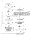
- a user sets a target out-bound temperature Th of hot water in the water-refrigerant heat exchanger 7 by the remote controls 12 (step 1).
- the out-bound temperature detection sensor 15 always detects an out-bound temperature To (step 4). In step 5, the out-bound temperature To and the target out-bound temperature Th are compared with each other. If it is determined in step 5 that the out-bound temperature To is lower than a value in which a predetermined temperature Ta (e.g., 2°C) is added to the target out-bound temperature Th, the compressor 3 is operated (step 6).
- a predetermined temperature Ta e.g., 2°C
- the hot water circulation pump 9 is driven and hot water is supplied to the water-refrigerant heat exchanger 7.
- the boiling operation carried out by the heat pump cycle 2 is continued until the out-bound temperature To detected by the out-bound temperature detection sensor 15 exceeds the target out-bound temperature Th.
- high temperature refrigerant discharged from the compressor 3 flows into the water-refrigerant heat exchanger 7, the high temperature refrigerant radiates heat and high hot water can be produced.
- water and refrigerant enhance the heat exchanging efficiency as countercurrent.
- step 7 it is determined whether an out-bound temperature To of hot water supplied from the water-refrigerant heat exchanger 7 detected by the out-bound temperature detection sensor 15 comes close to the target out-bound temperature Th (step 7). If the out-bound temperature To is within a predetermined temperature Tb (e.g., 5°C) with respect to the target out-bound temperature Th, it is determined in step 7 that the out-bound temperature To comes close to the target out-bound temperature Th, and the number of revolutions of the compressor 3 is reduced and the ability is lowered (step 8).
- Tb e.g., 5°C
- step 5 If it is determined in step 5 that the out-bound temperature To detected by the out-bound temperature detection sensor 15 becomes higher than the target out-bound temperature Th by a predetermined temperature Ta (e.g., 2°C), the operation of the compressor 3 is stopped and the carried out is completed (step 9).
- a predetermined temperature Ta e.g., 2°C
- the hot water circulation pump 9 is driven and hot water is circulated to the water-refrigerant heat exchanger 7. This is because that even if the boiling operation is being stopped, it is necessary to detect a temperature of hot water by the in-bound temperature detection sensor 14 and the out-bound temperature detection sensor 15, and if the temperature of hot water is lowered, the boiling operation carried out by the heat pump cycle 2 must immediately be restarted.
- the in-bound temperature Ti detected when the operation of the compressor 3 is stopped is stored as in-bound temperature-during stoppage Tim (step 10). Even during the operation of the compressor 3 is stopped also, the hot water circulation pump 9 is driven and the out-bound temperature To is always detected by the out-bound temperature detection sensor 15 (step 11). If it is determined that the out-bound temperature To detected by the out-bound temperature detection sensor 15 becomes lower than the in-bound temperature-during stoppage Tim stored when the operation of the compressor 3 is stopped by a predetermined temperature Tb (e.g., 5°C) (step 12), the operation of the compressor 3 is restarted and the boiling operation is started (step 13).
- Tb e.g., 5°C
- the in-bound temperature Ti detected by the in-bound temperature detection sensor 14 is 53°C, it is recorded that the in-bound temperature-during stoppage Tim is 53°C.
- the hot water circulation pump 9 is driven even after the boiling operation carried out by the compressor 3 is completed.
- the operation of the compressor 3 is restarted.
- Tc e.g., 5°C
- a case where an operation is carried out at different target out-bound temperatures Th by the remote controls 12a to 12c which respectively correspond to the plurality of floor heating panels 13a to 13c in step 2 will be described.
- a target out-bound temperature Th when an heating operation is carried out based on its temperature setting is determined, but when two or more floor heating panels 13 are operated, the target out-bound temperature Th1 of the floor heating panel 13 is employed (step 3).
- a floor heating panel 13 having a low target out-bound temperature Th opens and closes the thermally actuated valves 11b, 11c and 11d with a predetermined period, and an input heat quantity to the floor heating panel 13 is adjusted (step 14).
- Fig. 3 is a timing chart of an operation example at different target out-bound temperatures Th with the remote controls 12a to 12c which respectively corresponds to the plurality of floor heating panels 13a to 13c.
- a set temperature lower than the remote control 12a is instructed by the remote control 12b
- the opened thermally actuated valves 11b and 11c are closed, and the intermittent operations are started (timing (a)).
- the closed thermally actuated valves 11b and 11c maintain their closed state, and the intermittent operations are started (timing (b)).
- the intermittent operations of the thermally actuated valves 11b and 11c are reset, and the intermittent operations are newly started from timing (b). If the thermally actuated valve 11d is opened during the opening operation of the thermally actuated valves 11b and 11c in the intermittent operations, the thermally actuated valve 11d is closed at closing timing of the thermally actuated valves 11b and 11c in the intermittent operations (timing (c)).
- the intermittent operations of the thermally actuated valves 11b and 11c are reset at this changing timing, and the thermally actuated valves 11b and 11c are closed (timing (d)).
- the period is reset, and it is possible to perform the control while always predicting the flow rate reduction timing caused by the intermittent operation.
- operation is carried out while reducing the operation frequency which is heating ability of the compressor 3 of the heat pump cycle 2 before the thermally actuated valves 11b, 11c and 11d are closed. Therefore, it is possible to avoid a case where the hot water flow rate is reduced, a quantity of heat transferred from a refrigerant to hot water is reduced and the refrigerant becomes the high temperature and high pressure refrigerant.
- the present invention can provide a heat pump hydronic heater which can be operated at different target out-bound temperatures with the remote controls 12a to 12c which respectively correspond to the plurality of floor heating panels 13a to 13c while enhancing the comfort.
- the floor heating panels of a plurality of rooms are operated at different floor temperatures, thereby enhancing the comfort. Therefore, the invention can be applied to heating devices such as a water heater including a hot water circuit, a floor heating device, and a hot water heating device.
Landscapes
- Engineering & Computer Science (AREA)
- Physics & Mathematics (AREA)
- Thermal Sciences (AREA)
- Chemical & Material Sciences (AREA)
- Combustion & Propulsion (AREA)
- Mechanical Engineering (AREA)
- General Engineering & Computer Science (AREA)
- Computer Hardware Design (AREA)
- Steam Or Hot-Water Central Heating Systems (AREA)
Applications Claiming Priority (1)
| Application Number | Priority Date | Filing Date | Title |
|---|---|---|---|
| JP2011228595A JP2013088021A (ja) | 2011-10-18 | 2011-10-18 | ヒートポンプ式温水暖房装置 |
Publications (2)
| Publication Number | Publication Date |
|---|---|
| EP2589883A2 true EP2589883A2 (de) | 2013-05-08 |
| EP2589883A3 EP2589883A3 (de) | 2014-06-11 |
Family
ID=47018904
Family Applications (1)
| Application Number | Title | Priority Date | Filing Date |
|---|---|---|---|
| EP12188859.8A Withdrawn EP2589883A3 (de) | 2011-10-18 | 2012-10-17 | Hydronischer Wärmepumpenheizer |
Country Status (3)
| Country | Link |
|---|---|
| EP (1) | EP2589883A3 (de) |
| JP (1) | JP2013088021A (de) |
| CN (1) | CN103062819A (de) |
Families Citing this family (5)
| Publication number | Priority date | Publication date | Assignee | Title |
|---|---|---|---|---|
| CN103542447A (zh) * | 2013-11-05 | 2014-01-29 | 西诺信传感技术(天津)有限公司 | 一种燃气热泵与地板采暖结合的供热系统 |
| CN104864480B (zh) * | 2014-02-24 | 2018-09-11 | 珠海格力电器股份有限公司 | 空气源热泵地板采暖系统的调试方法 |
| CN109579188A (zh) * | 2018-12-15 | 2019-04-05 | 浙江永德信科技有限公司 | 用于辐射空调系统的自控和暖通一体机 |
| CN114756066B (zh) * | 2022-02-28 | 2024-03-22 | 青岛海尔空调电子有限公司 | 具有多个用水终端的水系统及其控制方法和控制装置 |
| CN118532744A (zh) * | 2024-05-31 | 2024-08-23 | 浙江中广电器集团股份有限公司 | 一种空气源热泵采暖系统在峰谷电模式下的能量调节方法 |
Citations (1)
| Publication number | Priority date | Publication date | Assignee | Title |
|---|---|---|---|---|
| JP2010203749A (ja) | 2009-03-06 | 2010-09-16 | Daikin Ind Ltd | 暖房装置 |
Family Cites Families (6)
| Publication number | Priority date | Publication date | Assignee | Title |
|---|---|---|---|---|
| NL8200316A (nl) * | 1982-01-28 | 1983-08-16 | Willempje Johanna Dogger Lam | Centrale verwarmingsinrichting. |
| DE4203613C2 (de) * | 1992-02-07 | 1998-01-22 | Sandler Energietechnik | Steuersystem für Raumheizanlagen |
| JP3894397B2 (ja) * | 1998-08-14 | 2007-03-22 | 東京瓦斯株式会社 | 温水又は冷水循環式空調システムにおける温水又は冷水の供給制御方法 |
| JP4244877B2 (ja) * | 2004-07-29 | 2009-03-25 | 株式会社ノーリツ | 温水暖房システム |
| JP2008232576A (ja) * | 2007-03-22 | 2008-10-02 | Sanden Corp | 給湯装置 |
| EP2505940B1 (de) * | 2009-11-25 | 2018-07-25 | Mitsubishi Electric Corporation | Steuervorrichtung für einen zuheizer, system mit verwendung von erhitzter flüssigkeit und steuerverfahren für zuheizer |
-
2011
- 2011-10-18 JP JP2011228595A patent/JP2013088021A/ja active Pending
-
2012
- 2012-10-17 EP EP12188859.8A patent/EP2589883A3/de not_active Withdrawn
- 2012-10-18 CN CN201210396369XA patent/CN103062819A/zh active Pending
Patent Citations (1)
| Publication number | Priority date | Publication date | Assignee | Title |
|---|---|---|---|---|
| JP2010203749A (ja) | 2009-03-06 | 2010-09-16 | Daikin Ind Ltd | 暖房装置 |
Also Published As
| Publication number | Publication date |
|---|---|
| JP2013088021A (ja) | 2013-05-13 |
| CN103062819A (zh) | 2013-04-24 |
| EP2589883A3 (de) | 2014-06-11 |
Similar Documents
| Publication | Publication Date | Title |
|---|---|---|
| CN203629017U (zh) | 空气调节装置 | |
| GB2524673B (en) | Heat pump system | |
| EP2299202A2 (de) | Wärmepumpendurchlauferhitzer | |
| US9927133B2 (en) | Air conditioning system | |
| KR101505856B1 (ko) | 공기조화기 및 그 제어방법 | |
| EP2610558B1 (de) | Wärmepumpensystem und steuerungsmethode einer wärmepumpe eines wärmepumpensystems | |
| JP5861726B2 (ja) | 空気調和システム | |
| KR101673105B1 (ko) | 2원 냉동 사이클 장치 | |
| EP2589883A2 (de) | Hydronischer Wärmepumpenheizer | |
| JP2013119954A (ja) | ヒートポンプ式温水暖房機 | |
| JP2017020672A (ja) | ヒートポンプ式温水装置 | |
| JP2012032091A (ja) | ヒートポンプサイクル装置 | |
| JP2017067318A (ja) | 空気調和装置 | |
| EP3032179B1 (de) | Erwärmungsvorrichtung vom heisswassertyp | |
| KR101514896B1 (ko) | 히트펌프 난방시스템 | |
| JP5254660B2 (ja) | 温水暖房装置の制御方法 | |
| EP2527757A1 (de) | Klimaanlage | |
| JP7199529B2 (ja) | 制御装置、空気環境調整システム、空気環境調整方法、プログラム、及び記録媒体 | |
| JP2012097953A (ja) | ヒートポンプ式温水暖房機 | |
| JP2004257645A (ja) | 温水暖房装置およびその制御方法 | |
| JP2004232947A (ja) | ヒートポンプ式温水暖房装置 | |
| CN107120862B (zh) | 一种酒柜换热系统及其控制方法和装置、及酒柜 | |
| EP3611434A1 (de) | Vorrichtung zum hydronischen erwärmen und verfahren zum hydronischen erwärmen | |
| JP2017180997A (ja) | 給湯空調システム | |
| JP2019066059A (ja) | 温水床暖房装置 |
Legal Events
| Date | Code | Title | Description |
|---|---|---|---|
| PUAI | Public reference made under article 153(3) epc to a published international application that has entered the european phase |
Free format text: ORIGINAL CODE: 0009012 |
|
| AK | Designated contracting states |
Kind code of ref document: A2 Designated state(s): AL AT BE BG CH CY CZ DE DK EE ES FI FR GB GR HR HU IE IS IT LI LT LU LV MC MK MT NL NO PL PT RO RS SE SI SK SM TR |
|
| AX | Request for extension of the european patent |
Extension state: BA ME |
|
| PUAL | Search report despatched |
Free format text: ORIGINAL CODE: 0009013 |
|
| AK | Designated contracting states |
Kind code of ref document: A3 Designated state(s): AL AT BE BG CH CY CZ DE DK EE ES FI FR GB GR HR HU IE IS IT LI LT LU LV MC MK MT NL NO PL PT RO RS SE SI SK SM TR |
|
| AX | Request for extension of the european patent |
Extension state: BA ME |
|
| RIC1 | Information provided on ipc code assigned before grant |
Ipc: F24D 3/18 20060101AFI20140508BHEP Ipc: F24D 19/10 20060101ALI20140508BHEP |
|
| STAA | Information on the status of an ep patent application or granted ep patent |
Free format text: STATUS: THE APPLICATION IS DEEMED TO BE WITHDRAWN |
|
| 18D | Application deemed to be withdrawn |
Effective date: 20141212 |