EP2589885A2 - Entgaser für ein Wasserheizsystem - Google Patents
Entgaser für ein Wasserheizsystem Download PDFInfo
- Publication number
- EP2589885A2 EP2589885A2 EP12191119.2A EP12191119A EP2589885A2 EP 2589885 A2 EP2589885 A2 EP 2589885A2 EP 12191119 A EP12191119 A EP 12191119A EP 2589885 A2 EP2589885 A2 EP 2589885A2
- Authority
- EP
- European Patent Office
- Prior art keywords
- water
- vessel
- aerator
- chamber
- outlet
- Prior art date
- Legal status (The legal status is an assumption and is not a legal conclusion. Google has not performed a legal analysis and makes no representation as to the accuracy of the status listed.)
- Granted
Links
- XLYOFNOQVPJJNP-UHFFFAOYSA-N water Substances O XLYOFNOQVPJJNP-UHFFFAOYSA-N 0.000 title claims abstract description 288
- 238000005276 aerator Methods 0.000 title claims abstract description 135
- 238000010438 heat treatment Methods 0.000 title claims abstract description 85
- 230000007423 decrease Effects 0.000 claims abstract description 13
- 238000005273 aeration Methods 0.000 claims abstract description 12
- 230000007704 transition Effects 0.000 claims description 19
- 239000012530 fluid Substances 0.000 claims description 18
- 238000004891 communication Methods 0.000 claims description 11
- 239000007789 gas Substances 0.000 description 25
- IJGRMHOSHXDMSA-UHFFFAOYSA-N Atomic nitrogen Chemical compound N#N IJGRMHOSHXDMSA-UHFFFAOYSA-N 0.000 description 18
- 238000011144 upstream manufacturing Methods 0.000 description 13
- 230000008901 benefit Effects 0.000 description 11
- 230000015572 biosynthetic process Effects 0.000 description 9
- 229910052757 nitrogen Inorganic materials 0.000 description 9
- QVGXLLKOCUKJST-UHFFFAOYSA-N atomic oxygen Chemical compound [O] QVGXLLKOCUKJST-UHFFFAOYSA-N 0.000 description 8
- 239000001301 oxygen Substances 0.000 description 8
- 229910052760 oxygen Inorganic materials 0.000 description 8
- 238000012360 testing method Methods 0.000 description 8
- 230000008859 change Effects 0.000 description 7
- 238000000034 method Methods 0.000 description 7
- 230000009467 reduction Effects 0.000 description 6
- 230000007797 corrosion Effects 0.000 description 5
- 238000005260 corrosion Methods 0.000 description 5
- 230000008878 coupling Effects 0.000 description 5
- 238000010168 coupling process Methods 0.000 description 5
- 238000005859 coupling reaction Methods 0.000 description 5
- 230000000694 effects Effects 0.000 description 5
- 238000009434 installation Methods 0.000 description 5
- 238000005406 washing Methods 0.000 description 5
- 229910001209 Low-carbon steel Inorganic materials 0.000 description 3
- 230000001133 acceleration Effects 0.000 description 3
- 230000008030 elimination Effects 0.000 description 3
- 238000003379 elimination reaction Methods 0.000 description 3
- 230000006872 improvement Effects 0.000 description 3
- 239000000463 material Substances 0.000 description 3
- 230000001737 promoting effect Effects 0.000 description 3
- CWYNVVGOOAEACU-UHFFFAOYSA-N Fe2+ Chemical compound [Fe+2] CWYNVVGOOAEACU-UHFFFAOYSA-N 0.000 description 2
- 230000009286 beneficial effect Effects 0.000 description 2
- 239000000470 constituent Substances 0.000 description 2
- 230000003247 decreasing effect Effects 0.000 description 2
- 239000000203 mixture Substances 0.000 description 2
- 230000008569 process Effects 0.000 description 2
- 238000005086 pumping Methods 0.000 description 2
- 238000012546 transfer Methods 0.000 description 2
- 239000000654 additive Substances 0.000 description 1
- 238000013019 agitation Methods 0.000 description 1
- 230000004888 barrier function Effects 0.000 description 1
- 230000005540 biological transmission Effects 0.000 description 1
- 238000006243 chemical reaction Methods 0.000 description 1
- 150000001875 compounds Chemical class 0.000 description 1
- 238000010276 construction Methods 0.000 description 1
- 230000007812 deficiency Effects 0.000 description 1
- 238000005265 energy consumption Methods 0.000 description 1
- 230000003090 exacerbative effect Effects 0.000 description 1
- 230000009931 harmful effect Effects 0.000 description 1
- 239000008236 heating water Substances 0.000 description 1
- 230000001771 impaired effect Effects 0.000 description 1
- 230000004048 modification Effects 0.000 description 1
- 238000012986 modification Methods 0.000 description 1
- 230000037361 pathway Effects 0.000 description 1
- 238000009420 retrofitting Methods 0.000 description 1
- 238000007493 shaping process Methods 0.000 description 1
- 239000000126 substance Substances 0.000 description 1
Images




Classifications
-
- F—MECHANICAL ENGINEERING; LIGHTING; HEATING; WEAPONS; BLASTING
- F24—HEATING; RANGES; VENTILATING
- F24D—DOMESTIC- OR SPACE-HEATING SYSTEMS, e.g. CENTRAL HEATING SYSTEMS; DOMESTIC HOT-WATER SUPPLY SYSTEMS; ELEMENTS OR COMPONENTS THEREFOR
- F24D19/00—Details
- F24D19/08—Arrangements for drainage, venting or aerating
- F24D19/082—Arrangements for drainage, venting or aerating for water heating systems
- F24D19/083—Venting arrangements
-
- B—PERFORMING OPERATIONS; TRANSPORTING
- B01—PHYSICAL OR CHEMICAL PROCESSES OR APPARATUS IN GENERAL
- B01D—SEPARATION
- B01D17/00—Separation of liquids, not provided for elsewhere, e.g. by thermal diffusion
- B01D17/02—Separation of non-miscible liquids
- B01D17/0217—Separation of non-miscible liquids by centrifugal force
-
- B—PERFORMING OPERATIONS; TRANSPORTING
- B04—CENTRIFUGAL APPARATUS OR MACHINES FOR CARRYING-OUT PHYSICAL OR CHEMICAL PROCESSES
- B04C—APPARATUS USING FREE VORTEX FLOW, e.g. CYCLONES
- B04C5/00—Apparatus in which the axial direction of the vortex is reversed
- B04C5/08—Vortex chamber constructions
- B04C5/081—Shapes or dimensions
Definitions
- the present invention relates to a de-aerator for a water heating system.
- the present invention relates to a de-aerator for removing dissolved gasses from water in a water heating system, and to a water heating system comprising such a de-aerator.
- Water heating systems are employed in both domestic and industrial environments for space heating and/or for supplying hot water for washing purposes.
- Water heating systems employ a primary heater, which is typically a gas or oil fired boiler. Where the heating system is to be used in a building for space heating purposes, the system comprises a network of space heaters. These space heaters are heat exchangers, and are generally referred to as "radiators".
- the primary heater is coupled to the radiators in a closed loop by means of a network of pipes, which includes a primary pipe circuit coupled to the boiler, and branch pipes extending from the primary pipe circuit to the radiators. The primary heater is activated to heat water in the primary pipe circuit, which is pumped around the primary pipe circuit and fed to the radiators by the branch pipes.
- the heated water passes around the primary pipe circuit and through the radiators, heat is transferred to the air via the radiators, to warm the building.
- the heated water flowing from the boiler into the primary pipe circuit is known as the "primary flow”
- the water returning to the boiler through the pipe circuit is known as the "primary return”.
- the primary return As a result of heat transfer to the radiators, and thermal losses in the pipe network, the water returning to the boiler (the primary return) is at a lower temperature than the water exiting the boiler (the primary flow).
- a hot water storage vessel or tank is provided in a secondary circuit which receives water from the primary pipe circuit. Water from the primary circuit enters the secondary circuit and passes through a coiled pipe located in the tank. This serves for heating a volume of ambient temperature water that has been charged into the tank. The water in the tank is thus indirectly heated by the primary flow, and the heated water that is outputted from the secondary circuit containing the tank is referred to as the "secondary flow".
- the water which is utilised in water heating systems for space heating purposes contains a relatively large proportion of dissolved air, which is a mixture of a number of different gases.
- the primary constituents of air are Nitrogen ( ⁇ 78%) and Oxygen ( ⁇ 21%). It has been calculated that the typical proportion of dissolved air in water is around 0.023g/kg (or around 0.0227g/litre) for water at a temperature of 25°C. In terms of volume, it is estimated that water at room temperature will contain up to around 2.5% by volume of dissolved air. In other words, 1001itres of water will contain up to around 2.5litres of dissolved air.
- Nitrogen being the largest constituent of air
- microscopic bubbles of Nitrogen can line the network of pipes and radiators, forming a thermal barrier which reduces the effective transfer of heat to the radiators, thereby impairing performance.
- the bubbles lining the pipes and radiators increase surface friction, and thus the resistance to flow of water through the pipes and radiators.
- a de-aerator for use in a water heating system, the de-aerator comprising:
- the velocity of water flowing through the chamber from the inlet to the outlet progressively increases, due to the shape of the chamber and in particular the shape of the side wall of the vessel.
- This increase in velocity results in a reduction in the pressure of the water in a direction towards the outlet.
- This reduction in pressure causes air dissolved in the water to come out of solution, forming bubbles of gas which can be directed out of the chamber through the vent. Additionally, gases which come out of solution as a result of heating of the water by the primary heater can also be directed out of the chamber through the vent.
- the de-aerator of the present invention offers numerous advantages over prior de-aerators.
- providing a vessel which is shaped to have a decreasing diameter towards the outlet, and which has a side wall with the curvature set out above is such that the vessel promotes a smooth flow of water from the inlet to the outlet; steady acceleration of the water towards the outlet and thus a steady pressure drop towards the outlet; and the formation of a stable vortex.
- the effective removal of dissolved air from the water in the heating system increases the thermal capacity of the system; it may effectively increase the density of the water.
- the vessel in particular the chamber, may be at least partially egg-shaped or ovoid.
- the side wall may have a shape which generally conforms to the shape of part of the surface of an egg, in particular part of a wall of an egg which extends in a direction from a portion of the egg of greatest external diameter towards an axial end of the egg, which end is the end adjacent the portion of the egg having the smallest radius of curvature.
- the vessel may have a main axis and may be symmetrical about the main axis.
- the side wall may have a radius of curvature which progressively decreases in a direction from the inlet towards the outlet. This may promote smooth flow, steady acceleration, and formation of a stable vortex, as discussed above.
- the rate of change of the radius of curvature may increase in a direction towards the outlet.
- Said side wall may extend at least between an opening of the inlet and an opening of the outlet.
- the curvature of the side wall and thus of the chamber may be determined by the diameter of the vessel, and the way in which the diameter changes in a direction from the inlet towards the outlet.
- the vessel, or the portion of the vessel defined by the side wall may have a length, and the diameter may decrease in a direction from a top of the vessel (or the top of the portion of the vessel defined by the side wall) to a bottom of the vessel.
- a ratio of the diameter of the vessel relative to the length at that position may be from about 4.250 to about 4.260.
- a ratio of the diameter of the vessel relative to the length at that position may be from about 2.040 to about 2.050.
- a ratio of the diameter of the vessel relative to the length at that position may be from about 1.260 to about 1.270.
- a ratio of the diameter of the vessel relative to the length at that position may be about 0.820 to about 0.830.
- a ratio of the diameter of the vessel relative to the length at that position may be about 0.470 to about 0.480.
- a ratio of the diameter of the vessel relative to the length at that position may be about 0.170 to about 0.180.
- a vessel having such a shape, and thus the chamber, may be generally egg-shaped or ovoid.
- the vessel will be positioned so that a main axis is vertically oriented, and references to the top and bottom of the vessel should be interpreted accordingly.
- the vessel may have a further portion above the inlet, say where the inlet is located between an axially upper extent of the vessel and a lower extent.
- the side wall referred to above is the portion of the vessel wall extending between the inlet and the outlet, and the top of the vessel referred to above would then be the portion of the vessel in the region of the inlet.
- the side wall of the vessel may have radii of curvature which are positive, taken with reference to centres of curvature located within the chamber.
- the portion of the vessel defined by the side wall may be said to be generally convex in shape.
- the radius of curvature of the side wall in the region of the outlet, relative to a radius of the vessel may be about 1:2, may be between about 1:2 and about 1:3, and is preferably about 1:3.
- the radius of curvature of the side wall in the region of the outlet may be about 30mm, may be between 30mm and 20mm, and is preferably about 20mm.
- the de-aerator may comprise a flow conduit coupled to the vessel outlet so that fluid exiting the outlet flows through the flow conduit.
- the flow conduit may have a conduit axis, and may be positioned so that it is coaxial with the vessel outlet, or may have a portion which is positioned so that it is coaxial with the vessel outlet.
- the flow conduit (or said portion of the flow conduit) may have a length of at least about 200mm, optionally at least about 250mm, and may have a length of at least about 300mm. In a preferred embodiment, the flow conduit may have a length of at least about 600mm.
- the vessel is typically positioned so that the outlet is in a vertical orientation, and so the flow conduit or conduit portion, which is coaxial with the outlet, is similarly vertically oriented.
- the flow conduit/conduit portion at least about300mm, and preferably at least about 600mm, provides a vertical drop of at least that dimension before there is any subsequent change in angle of the flowing water (such as for direction in a lateral or horizontal direction towards a space heater). This produces particularly good results.
- the vessel may comprise an outlet conduit which defines the vessel outlet, and a transition portion extending between the outlet conduit and the side wall of the vessel.
- the transition portion may be shaped to promote the smooth flow of water through the outlet without resultant turbulence which could otherwise disrupt the flow.
- the transition portion may be curved, and may have a diameter which decreases in a direction from the side wall towards the outlet conduit.
- the radius of curvature of the transition portion may be constant, and may be negative, taken with reference to a centre of curvature located within the chamber.
- a wall of the transition portion of the vessel may be said to be generally concave in shape, in cross-section.
- the radius of curvature of the transition portion may be about 1:3, may be about 1:4, may be about 1:5, and is preferably about 1:6.
- the radius of curvature of the transition portion may be about 20mm, may be about 15mm, may be about 12mm, and is preferably about 10mm.
- the outlet may have an outlet axis, and may be positioned so that the outlet axis is parallel to a main axis of the vessel.
- the outlet may be coaxial with a main axis of the vessel.
- the outlet may be positioned on an axial end of the vessel, which end may be a lowermost end of the vessel, in use.
- the vessel will be positioned in use so that the outlet is located lowermost, to promote the flow of water through the chamber and formation of a vortex. Accordingly, the vessel will typically be positioned in a generally vertical orientation.
- the inlet may be shaped to direct water into the chamber generally tangentially to an internal surface of the chamber, in particular to an internal surface of the side wall. This may facilitate the formation of a vortex within the chamber, by promoting flow of water in a helical path within the chamber from the inlet towards the outlet.
- the inlet may comprise an entry portion through which water is fed into the inlet, and an exit portion through which water flows into the chamber.
- the exit portion may define an exit which is shaped to direct the water generally tangentially.
- the entry and exit portions may be disposed at non-parallel angles relative to one another.
- the entry portion may define an entry, and may be positioned so that an axis of the entry portion is parallel to a main axis of the vessel (and so not coaxially oriented).
- the entry portion may be positioned so that its axis is parallel to and spaced from the main axis of the vessel.
- the inlet may be provided in a lid or cap of the vessel, and may be positioned between a radially outer edge of the lid and a centre of the lid.
- the chamber may have an upper portion and a lower portion.
- the inlet may open on to the upper portion of the chamber.
- the outlet may open on to the lower portion of the chamber.
- the upper portion of the chamber may be of a greater diameter than the lower portion of the chamber, and may be of greater diameter than a remainder of the chamber.
- the inlet may open on to an intermediate portion of the chamber, which is between the upper portion and the lower portion.
- the intermediate portion of the chamber may be of greater diameter than either the upper or lower portions.
- the vent may comprise a vent conduit or pipe having an inlet located in the chamber and an outlet located externally of the chamber, for directing gasses out of the chamber.
- the inlet may be positioned so that, in use, the inlet is submerged in the water in the chamber. This may prevent exposure of the inlet which could otherwise result in air being drawn into the chamber through the vent conduit.
- the inlet may be positioned so that it is coaxial with a main axis of the vessel. In this way, the vent conduit inlet may be located in the centre of the vessel, and may therefore be located at the centre of a vortex which is created when water flows through the vessel. This may facilitate discharge of gas through the vent conduit.
- the vent conduit inlet may be positioned generally in the region of the outlet.
- vent conduit inlet Positioning the vent conduit inlet in the region of the outlet may promote the escape of these gases from the chamber.
- a cross-sectional area of the vent conduit inlet may be greater than a cross-sectional area of the outlet. This may promote flow of gases into and along the conduit, without requiring a conduit which has a large outlet, relative to a diameter of the vessel.
- the de-aerator may comprise a magnetic element for removing ferrous materials from the water.
- the magnetic element may be positioned below the outlet of the vessel, and may be located in the outlet conduit or the flow conduit.
- a water heating system comprising:
- the volume of the de-aerator chamber as a proportion of the total volume of water in the heating system (which may be the volume of water in the primary water conduit, the at least one space heater and any associated branch conduits) may be no more than about 1%, optionally no more than about 0.5%, and preferably no more than about 0.3% of the total volume. It has been found that there are benefits in terms of the performance of the de-aerator where the volume of the de-aerator chamber as a proportion of the total volume of water in the heating system is in this range, preferably no more than about 0.3%.
- the volume of the chamber may be no more than about 400ml, may be no more than about 350ml, may be no more than about 300ml, and preferably is about 280ml.
- the de-aerator may be positioned downstream of the primary heater, and may be upstream of the at least one space heater. In this way, the water is de-aerated prior to entering the at least one space heater.
- the de-aerator may be positioned downstream of a pump which is used to force water around the primary conduit, and upstream of a valve or valves which are used to control the flow of fluid in the system.
- the system may comprise a water storage vessel provided in a secondary circuit which is in fluid communication with the primary water conduit, water flowing from the primary circuit into the secondary circuit to heat ambient water contained within the storage vessel.
- the de-aerator may be positioned upstream of the water storage vessel.
- the system may comprise a secondary circuit having a secondary conduit coupled to the storage vessel so that water in the secondary conduit flows in a closed loop through the storage vessel, and at least one tap or faucet coupled to the secondary conduit for the discharge of heated water from the secondary circuit.
- the system may comprise a second de-aerator according to the first aspect of the present invention coupled in the secondary circuit.
- a water heating system comprising:
- the further secondary circuit may comprise a pump for continuously pumping the water around the circuit, so that the water which is discharged from the at least one tap or faucet is always hot.
- the de-aerator may act to de-aerate the water in the further secondary circuit, providing the advantages discussed above.
- a method of retrofitting a de-aerator in an existing water heating system comprising a primary water heater, a primary water conduit coupled to the primary heater so that water in the primary water conduit flows in a closed loop through the primary water heater, and at least one space heater arranged in fluid communication with the primary water conduit, the method comprising the steps of:
- the method may comprise removing a portion of the existing primary water conduit and positioning the de-aerator in its place.
- the step of removing the portion of the conduit may comprise making spaced upstream and downstream cuts in the conduit, to divide the conduit into upstream and downstream portions, and coupling the inlet of the de-aerator to the upstream portion and the outlet of the de-aerator to the downstream portion.
- the de-aerator may be coupled using suitable connecting conduits.
- Fig. 1 there is shown a side view of a de-aerator for use in a water heating system, in accordance with an embodiment of the present invention, the de-aerator indicated generally by reference numeral 10.
- the de-aerator 10 is also shown in the longitudinal cross-sectional view of Fig. 2 , and in Fig. 3 , which is a schematic illustration of a water heating system 12 incorporating the de-aerator 10.
- the de-aerator 10 generally comprises a vessel 14 defining a chamber 16 for receiving water which has been heated by a primary water heater 18.
- the vessel 14 has an inlet 20 through which water can be supplied into the chamber 16, an outlet 22 through which water can exit the chamber, and a vent 24 through which gas can exit the chamber.
- a diameter of the chamber 16 decreases in a direction from the inlet 20 towards the outlet 22.
- the vessel 14 has a side wall 26 extending between the inlet 20 and the outlet 22, which defines a boundary of the chamber 16.
- the side wall 26 is curved and has a non-constant radius of curvature, the radius of curvature being smaller in the region of the outlet 22 than in the region of the inlet 20. This is illustrated in Fig.
- a radius of curvature R 1 of the side wall 26 in the region of the outlet 22 is smaller than a radius of curvature R 2 in the region of the inlet 20.
- the side wall 26 effectively has a radius of curvature which progressively decreases in a direction from the inlet 20 towards the outlet 22. The rate of change of the radius of curvature may increase in a direction towards the outlet 22.
- the velocity of water flowing through the chamber 16 from the inlet 20 to the outlet 22 progressively increases, due to the shape of the chamber and in particular the shape of the side wall 26 of the vessel 14.
- This increase in velocity results in a reduction in the pressure of the water in a direction towards the outlet 22.
- This reduction in pressure causes air dissolved in the water to come out of solution, forming bubbles of gas which can be directed out of the chamber 16 through the vent 24.
- gases which come out of solution as a result of heating of the water by the primary heater 18 can also be directed out of the chamber 16 through the vent 24.
- the de-aerator of the present invention offers numerous advantages over prior de-aerators.
- shaping the vessel 14 so that it has a decreasing diameter towards the outlet 22, and so that the side wall 26 has the curvature set out above is such that the vessel 14 promotes a smooth flow of water from the inlet 20 to the outlet 22; steady acceleration of the water towards the outlet 22 and thus a steady pressure drop towards the outlet; and the formation of a stable vortex.
- the effective removal of dissolved air from the water in the heating system 12 increases the thermal capacity of the system; it may effectively increase the density of the water.
- the shape of the vessel 14 is such that it gradually funnels the water into a vortex.
- Nitrogen which comes out of solution from the water forms bubbles which enlarge to a size which is such that the bubbles have sufficient buoyancy to rise against the pumping velocity of water through the vessel 14, so that they can escape through the vent 26.
- Bubbles of Nitrogen and Oxygen also cluster together, to form bigger bubbles, which accelerates the process of eliminating dissolved air from the system 12.
- Tests of a heating system employing the de-aerator 10 have shown that, after only one week of use, the proportion of dissolved air in the system was reduced from a starting level of around 8 to 9ppm to just 0.2ppm.
- the water heating system 12 incorporating the de-aerator 10 will now be described in more detail.
- the primary heater 18 is of a conventional type, and is typically a gas or oil-fired boiler.
- the system 12 comprises a primary water circuit 27 having a conduit 28 coupled to the boiler 18 so that water in the primary water conduit flows in a closed loop through the boiler.
- At least one space heater is arranged in fluid communication with the boiler 18 and, in the illustrated embodiment, two space heaters in the form of heat exchangers known as radiators 30 and 32 are provided.
- the radiators 30 and 32 are coupled to the primary water conduit 28 by means of respective pairs of branch pipes or conduits 34, 36 and 38, 40.
- the radiators 30 and 32 serve for heating a room or rooms of a building (not shown) in a fashion which is well known in the art, heated water being supplied into the radiators via the primary water conduit 28 and the branch pipes 34, 38 (as indicated by the arrows in Fig. 2 ) and returning to the primary conduit through the branch pipes 36, 40.
- the system 12 additionally comprises a secondary circuit 41 including a hot water storage vessel 42, which is in fluid communication with the primary water conduit 28 by means of secondary pipes or conduits 44 and 46 so that the primary flow is diverted into the secondary circuit.
- the vessel 42 contains a volume of ambient temperature water 48 which is heated by the primary flow of water passing through from the inlet pipe 44, through a heating coil 50.
- a secondary flow of hot water can therefore be drawn off the storage vessel 42 for washing and other purposes, by means of a number of taps (or faucets), one of which is shown and given the reference numeral 52.
- the de-aerator 10 is arranged so that it is in fluid communication with the primary water conduit 28, so that the water flowing in the primary conduit flows through the de-aerator, which operates to de-aerate the water.
- a portion 28a of the primary conduit 28 is coupled to the vessel inlet 20, and the vessel outlet 22 is coupled to a portion 28b of the conduit, so that water flowing in the circuit around the primary conduit from the boiler 18 to the radiators 30, 32 and hot water storage vessel 42 flows through the de-aerator 10.
- the de-aerator 10 is thus positioned so that it is downstream of the boiler 18 but upstream of the radiators 30, 32 and storage vessel 42.
- the de-aerator 10 is typically located downstream of a pump 51 which drives water around the primary circuit, and upstream of a valve 53 which controls the flow of water around the primary circuit to the radiators 30 and 32, and/or through the secondary circuit 41 to the hot water storage vessel 42.
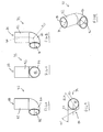
- Figs. 4, 5 and 6 are perspective, plan and side views, respectively, of an end cap or lid 54 of the de-aerator
- Fig. 7 is a cross-sectional view of the lid taken in the direction of the arrows A-A of Fig. 5
- Figs. 8, 9 and 10 are perspective, plan and side views, respectively, of the inlet 20, and Figs. 11 and 12 are views similar to Fig. 10 but taken from different angles.
- Figs. 13, 14 and 15 are perspective, plan and side views, respectively, of the vent 24, and Figs. 16 and 17 are views similar to Fig. 15 but taken from different angles.
- Fig. 18 is a sectional view of the de-aerator 10 shown in Fig 1 , which is similar to Fig. 2 , but which shows a relationship between a diameter and length of the vessel 14.
- the vessel 14, and thus the chamber 16, is in effect at least partially egg-shaped or ovoid, the side wall 26 having a shape which generally conforms to the shape of part of the surface of an egg, in particular part of a wall of an egg which extends in a direction from a portion of the egg of greatest external diameter towards an axial end of the egg, which end is the end adjacent the portion of the egg having the smallest radius of curvature.
- the side wall 26 has a curvature whose shape is determined according to its diameter and the way in which the diameter changes along the length of the chamber 16 in a direction from the inlet towards the outlet.
- the chamber 16 defmed by the side wall 26 has a length L, and the diameter decreases in a direction from a top 55 of the chamber to a bottom 57 of the chamber.
- the curvature of the side wall 26, and thus of the chamber 16, is determined by the diameter of the chamber, and the way in which the diameter changes in a direction from the inlet 20 towards the outlet 22.
- the chamber 16 is constructed so as to be generally egg-shaped by careful control of the chamber diameter.
- Optimised de-aeration effects may be achieved by dimensioning the chamber 16 as follows.
- the chamber 16 has been divided into six equal sections ( Fig. 18 ) in planes which are perpendicular to a main axis 66 of the vessel.
- the chamber 16 is symmetrical about the axis 66.
- a ratio of the diameter D 1 of the chamber relative to the length at that position is from about 4.250 to about 4.260, and in particular is about 4.260.
- a ratio of the diameter D 2 of the chamber relative to the length at that position is from about 2.040 to about 2.050, and in particular is about 2.050.
- a ratio of the diameter D 3 of the chamber relative to the length at that position is from about 1.260 to about 1.270, and in particular is about 1.260.
- a ratio of the diameter D 4 of the chamber relative to the length at that position is from about 0.820 to about 0.830, and in particular is about 0.820.
- a ratio of the diameter D 5 of the chamber relative to the length at that position is from about 0.470 to about 0.480, and in particular is about 0.480.
- a ratio of the diameter D 6 of the chamber relative to the length at that position is from about 0.170 to about 0.180, and in particular is about 0.180.
- the side wall 26 extends in a smooth curve between the upper end 55 of the chamber 16 and the lower end 57.
- a chamber having such a shape is generally egg-shaped or ovoid.
- the vessel 14 has a maximum outer diameter of 120mm.
- the thickness of the sidewall 26 is 1.5mm, so the maximum internal diameter of the vessel 16 (and thus the maximum diameter of the chamber) is around 117mm.
- the vessel 16 has a length L between the inlet 20 and the outlet 22 of 110mm, and so the lengths L 1 to L 5 are, respectively, 18.33mm; 36.67mm; 55mm; 73.33mm; and 91.67mm.
- the respective diameters D 1 to D 6 of the chamber 16 can therefore be calculated to be 78.00mm; 75.00mm; 69.50mm; 60.30mm; 44.00mm; and 19.70mm.
- the thickness of the side wall 26 the diameters of the chamber 16 at these positions can then be determined.
- the side wall 26 of the vessel 14 has radii of curvature which are positive, taken with reference to centres of curvature located within the chamber, as indicated by the example radii R 1 and R 2 discussed above, each of which have centres C 1 and C 2 in the chamber 16.
- the radius of curvature R 1 of the side wall 26 in the region of the outlet, relative to a maximum radius of the vessel is about 1:3.
- the vessel 14 has a radius R v of around 60mm, and so the radius of curvature R 1 is around 20mm.
- the radius of curvature of the side wall 26 is non-constant, and is greatest in the region of the outlet 22.
- the volume of the de-aerator chamber 16 as a proportion of the total volume of water in the heating system 12 (which is the volume of water in the primary water circuit and thus the conduit 28, radiators 30, 32 and secondary circuit 41) is no more than about 1%, optionally no more than about 0.5%, and preferably no more than about 0.3% of the total volume. It has been found that there are benefits in terms of the performance of the de-aerator 10 where the volume of the de-aerator chamber 16 as a proportion of the total volume of water in the heating system 12 is in this range, preferably no more than about 0.3%.
- the volume of the chamber may be no more than about 400ml, may be no more than about 350ml, may be no more than about 300ml, and in the illustrated embodiment is about 280ml.
- the de-aerator 10 also comprises a flow conduit coupled to the vessel outlet 22.
- the flow conduit is the portion 28b of the primary flow conduit shown in Fig. 3 .
- water exiting the outlet 22 flows through the flow conduit 28b.
- Part of the flow conduit 28b is shown in Fig. 1 , and has a conduit axis 56.
- the flow conduit 28b is positioned so that it is coaxial with the vessel outlet 22, and so is positioned so that the flow conduit axis 56 is coaxial with an axis 58 of the outlet 22.
- the flow conduit 28b has a length of at least about 600mm.
- the vessel 14 is typically positioned so that the outlet 22 is in a vertical orientation, and so the flow conduit 28b, which is coaxial with the outlet, is similarly vertically oriented.
- Making the flow conduit 28b at least about 600mm provides a vertical drop of at least that dimension before there is any subsequent change in angle of the flowing water, such as for direction in a lateral or horizontal direction towards the radiator 30, as shown in Fig. 3 .
- Reasonable results can also be achieved with a pipe length (and so drop) of around 300mm, but it has been found that a length of at least about 600mm provides particularly good results.
- the vessel 14 also comprises an outlet conduit 60 which defines the vessel outlet 22, and a transition portion 62 extending between the outlet conduit and the side wall 26 of the vessel.
- the transition portion 62 is shaped to promote the smooth flow of water through the outlet 22 without resultant turbulence which could otherwise disrupt the flow.
- the transition portion 62 is curved, and has a diameter which decreases in a direction from the side wall 26 towards the outlet conduit 60.
- a radius of curvature R 3 of the transition portion is constant, and is negative, taken with reference to a centre of curvature C 3 located within the chamber 16.
- a wall of the transition portion 62 can be said to be generally concave in shape in that it generally curves inwardly.
- the ratio of the radius of curvature R 3 of the transition portion 62, relative to a maximum radius R v of the vessel 14, is about 1:6. So, with the vessel radius R v being 60mm, the radius of curvature of the transition portion is about 10mm.
- the outlet 22 is positioned so that the outlet axis 58 is parallel to a main axis 66 of the vessel 14, and in the illustrated embodiment is coaxial with the main axis.
- the outlet 22 is also provided at a lower end 68 of the vessel 14, and is lowermost of the vessel. In this way, the flow of water through the chamber 16, and formation of a vortex, is promoted.
- the inlet 20 is defined by an inlet conduit 72 which is provided in the lid 54, and is positioned between a radially outer edge 74, and a centre 76, of the lid.
- the inlet conduit 72 is shaped to direct water into the chamber generally tangentially to an internal surface of the chamber, in particular to an internal surface 78 of the side wall 26. This is illustrated in Fig.
- the inlet conduit 72 also comprises an entry portion 82 through which water is fed into the inlet 20, and an exit portion 84 through which water flows into the chamber 16.
- the exit portion 84 defines an exit 86 which is shaped to direct the water generally tangentially.
- the entry and exit portions 82, 84 are disposed at non-parallel angles relative to one another so that the conduit 72 has a bent or curved profile.
- the entry portion 82 defines an entry 88, and is positioned so that an axis 70 of the entry portion is parallel to and spaced from a main axis 66 of the vessel (and so not coaxially oriented).
- the diameter of the chamber reduces, and the radius of curvature of the side wall 26 changes, particularly as the water transitions to the region of the chamber where the side wall 26 is of the smallest radius of curvature R 1 , in the region of the outlet 22.
- This causes a vortex to form in which the water is accelerated as it flows towards the outlet.
- the water will descend a smaller vertical distance for each full 360° traverse around the chamber 16.
- the vent 24 comprises a vent conduit or pipe 90 having an inlet 92 located in the chamber 16, and an outlet 94 located externally of the chamber, for directing gasses out of the chamber.
- a one-way valve 96 ( Fig. 3 ) will be coupled to the vent outlet 94 to permit gas to escape from the chamber 16, but prevent external air ingress.
- the inlet 92 is positioned so that, in use, it is submerged in the water in the chamber 16, preventing exposure of the inlet.
- the vent conduit 90 is also positioned so that the inlet 92 is coaxial with the main 66 axis of the vessel 14. In this way, the vent conduit inlet 92 is located in a centre of the vessel 14, and therefore at the centre of a vortex which is created when water flows through the vessel.
- vent conduit 90 This facilitates discharge of gas through the vent conduit 90. This is because, in use, bubbles of gas coming out of solution from the water will tend to be carried down with the water towards the outlet 22, and generally radially inwardly of the vessel (in particular into the centre of a vortex which may be formed in the tank). Positioning the vent conduit inlet 92 in the region of the outlet 22 may therefore promote the escape of such gases from the chamber.
- the vent pipe 90 is generally curved or bent, so as to provide a spacing between the outlet 94 and the vessel inlet conduit 72. It will be understood that the vent pipe 90 may be straight or may have some other shape, depending on factors including the overall diameter of the vessel 14 and the diameter of the vent pipe.
- the de-aerator 10 can also include a magnetic element (not shown), which would typically be a permanent magnet, for removing ferrous materials from the water.
- the magnetic element may be positioned below the outlet 22 of the vessel, and may be located in the outlet conduit 60 or the flow conduit 28b.
- the de-aerator 10 can be installed as part of a new water heating system or as a retro-fit item.
- the retro-fit method will be described with reference to the heating system 12 shown in Fig. 3 which, in this situation, would comprise all of the components shown and described above save for the de-aerator 10.
- the primary water conduit 28 would therefore extend in an unbroken path from the boiler 18 to the radiator 30 prior to installation of the de-aerator 10.
- the method involves coupling the de-aerator 10 to the primary water conduit 28 at a position which is downstream of the boiler 18, and upstream of the radiators 30 and 32 (such as in the position shown in Fig. 3 ). A portion of the existing primary water conduit 28 is removed and the de-aerator 10 positioned in its place.
- the de-aerator 10 may be coupled into the system 12 using suitable connecting conduits.
- the applicant has performed tests of a water heating system of the type shown in Fig. 3 both prior to installation of a de-aerator of the type shown in Fig. 1 , and following installation of the de-aerator. After installation of the de-aerator, it has been found possible to turn a thermostat setting on the system boiler down from a near maximum setting to a much lower operating level, effectively around 20% to 30% of the previous setting. Also, it has been found that the building in which the heating system is installed heats up to the required level nearly three times faster than it did prior to installation of the de-aerator. This was a surprising improvement in performance, believed to result from the effective removal of air from the water in the system 12, leading to many benefits including reduced energy usage and wear and tear on the boiler and other heating system components, and also returning the heating, or primary water, to a potable state.
- the system can include a further secondary circuit 98, which is shown in broken outline in the drawing.
- the secondary circuit 98 includes a number of taps or faucets 52a-c which are coupled in a closed loop to the storage vessel 42.
- a pump 100 is used to continuously drive hot water around the secondary circuit 98 so that hot water can be drawn off through one or more of the taps 52a-c on demand, and without a significant delay between turning on of the tap and the supply of hot water.
- a second de-aerator 102 of like construction to the de-aerator 10 described above is provided in the secondary circuit 98, for de-aerating the water in the circuit.
- a water heating system (not shown) may be provided employing a single de-aerator in a secondary circuit such as the circuit 98.
- Figs. 19, 20 , 21 and 22 there are shown front, right side, plan and perspective views, respectively, of a de-aerator for use in a heating system in accordance with another embodiment of the present invention, the de-aerator indicated generally by reference numeral 10'.
- the de-aerator 10' Like components of the de-aerator 10' with the de-aerator 10 of Figs. 1 and 2 share the same reference numerals, with the addition of the suffix'. Only the substantive differences between the de-aerator 10' and the de-aerator 10 will be described herein.
- the de-aerator 10' comprises a side-entry type inlet 12' having an inlet conduit 72' which is substantially straight, and arranged to direct water into a chamber 16' defined by a vessel 14' of the de-aerator generally tangentially, as can best be appreciated from Figs. 20 and 21 .
- the inlet 12' opens on to an intermediate portion 103 of the chamber, which is between an upper portion 104 and a lower end 68'.
- a side wall 26' of the intermediate portion 103 extends between the inlet 12' and an outlet 22', and is curved with a non-constant radius of curvature, as discussed above.
- the upper portion 104 of the vessel 14' above the inlet 12' is generally domed, being approximately hemi-spherical in shape.
- the de-aerator 10' includes a vent 24' in the form of a straight pipe, which is coaxially oriented relative to a main axis 66' of the vessel 14'.
- the inlet conduit 72' is internally threaded, and flat surfaces (or “flats") 106 and 108 are provided on an external surface 110 of the inlet conduit 72'.
- the flats 106 and 108 facilitate coupling of a primary water conduit of a heating system, such as the conduit 28 shown in Fig. 3 , to the de-aerator 10'.
- the flats 106 and 108 allow for a spanner or like tool to be coupled to the conduit 72' so that, when a primary water conduit or connector is threaded into the inlet conduit 72', the transmission of torque to a joint region 112 ( Fig. 21 ) between the conduit 72' and the vessel 14' is reduced.
- the de-aerator vessel 14' may be of different dimensions, and/or internal volume, to the vessel 14 described above.
- the part of the chamber 16' in the intermediate portion 103 extending down to the lower end 68' may have a different internal diameter, and/or the ratios of diameter to length of said portion may be different to that described above.
- the side-wall 26' of the vessel 14' is shaped so that the vessel remains generally egg-shaped, promoting the de-aeration effects described above.
- Fig. 23 is a graph showing temperature against time for a heating system incorporating a primary water heater in the form of a gas-fired boiler of a conventional type, over a two hour period.
- the line 114 represents the primary flow temperature over that period, that is the temperature of the water exiting the boiler.
- the line 114 shows peaks and troughs in the primary flow temperature, which are indicative of periods when the boiler is active, shown by the part of the line building up to the temperature peaks or "spikes" 116; and the periods when the boiler is inactive, shown by the part of the line falling down to the temperature troughs 118.
- the line 120 represents the primary return temperature over that period, that is the temperature of the water returning to the boiler following passage through the heating system.
- the line 120 shows peaks 122 and troughs 124 in the primary return temperature, which correspond to the peaks and troughs of the primary flow, when the boiler is active/inactive. There is a difference of approximately 7 to 8°C between the corresponding primary flow peaks 116 and primary return peaks 122.
- Fig. 24 illustrates the same heating system with the de-aerator of the present invention installed, tested over the same period, primary flow indicated by line 114' and primary return by the line 120'.
- the primary flow builds to a temperature which is higher than that of the boiler operated without the de-aerator, at a stable temperature of around 75°C, compared to around 70°C.
- the difference between the peaks 116' of the primary flow and the peaks 122'of the primary return are much closer, with a difference of only around 2 to 3°C.
- the primary return temperature is significantly higher when employing the de-aerator, as indicated by the troughs 124'. As can be seen, the primary return temperature is around 60°C, in comparison to around 52°C without the de-aerator.
- a higher primary flow temperature is achieved without increased boiler burn time.
- boiler burn time is reduced.
- the higher temperature of the primary return is such that a lower heat input (and so boiler burn time) is required to reheat the water returning to the boiler, which further improves efficiency.
- the higher primary return heat is also indicative that the thermal capacity of the heating system has effectively been increased, with reduced losses.
- Fig. 25 is a graph showing the volume of removed air against time for another heating system incorporating a primary water heater in the form of a gas-fired boiler of a conventional type, over a two hour period. In this example, three lines 126, 128 and 130 are shown.
- the line 126 represents the volume of air naturally dissolving out of water in the heating system during operation of the boiler over the two hour period, with a flow rate of approximately 251/min, and an operating system pressure of 0.5 bar. Air exits the heating system through a vent having a one-way valve, this air coming out of solution due to the increase in temperature of the water, as discussed above.
- the line 128 illustrates a boiler of a different type but similar thermal capacity, operated over the same period and under similar operating conditions, the boiler having a built-in air elimination system. As can be seen, higher volumes of air are removed in this instance.
- the line 130 illustrates the heating system which produced the results indicated by the line 126, but with the de-aerator of the present invention installed. As can be seen, significantly higher volumes of air were removed, even in comparison to the boiler employing the air elimination system.
- Fig. 26 shows the results of the same test as that of Fig. 25 , save that a higher operating pressure of 1.5 bar was employed, the higher pressure resulting in a lower volume of dissolved air coming out of the water in the heating system, in all cases.
- the lines 126', 128' and 130' correspond to the tests shown and discussed in Fig. 25 , with the addition of the suffix'. The effect is slightly less marked in this instance, as can be seen from the line 130'. It is believed that this was due to the higher working pressure causing an O-ring seal on a float in the air vent of the de-aerator being pushed tighter against its seat, preventing the same high speed of air elimination being reached as shown in Fig. 25 .
- the de-aerator can provide up to 30% savings in energy consumption, by effectively increasing the efficiency of the heating system employing the de-aerator, and thereby reducing boiler burn time.
- Use of the de-aerator has also been found to result in a faster heat-up of the heating system. It has been found that radiators much further away from a boiler operate at a significantly higher heat than without the de-aerator. De-aeration of the water also results in the heat remaining in radiators for a longer period.
- a heating system employing the de-aerator has been found to be much quieter, due to the absence of air in the system.
- the de-aerator of the present invention providing such marked improvements in de-aerating water in a heating system is due to so-called "implosion” effects, which result from flow of the water through the specially shaped vessel of the de-aerator.
- the de-aerator stimulates a chemical change in the water in the heating system. Heat and agitation each play a part.
- the "egg-shape" of the de-aerator is such that, as the water enters the de-aerator, it experiences a change in direction (which is immediate in the embodiment shown in Figs. 1 and 2 ), and is then forced round and down the vessel very quickly.
- the radius of curvature of the side wall in the region of the outlet, relative to a radius of the vessel, may be about 1:2, or may be between about 1:2 and about 1:3.
- the radius of curvature of the side wall in the region of the outlet may be about 30mm, or may be between 30mm and 20mm.
- the flow conduit/portion of the flow conduit may have a length of at least about 200mm, or optionally at least about 250mm. Other lengths may be chosen, for example between 300 and 600mm, or greater than 600mm.
- the radius of curvature of the transition portion may be about 1:3, may be about 1:4, or may be about 1:5.
- the radius of curvature of the transition portion may be about 20mm, may be about 15mm, or may be about 12mm.
- the inlet may open on to an intermediate portion of the chamber, which is between the upper portion and the lower portion.
- the intermediate portion of the chamber may be of greater diameter than either the upper or lower portions.
- An area of the vent conduit inlet may be greater than an area of the outlet. This may promote flow of gases into and along the conduit.
- the de-aerator may have a utility in removing air from other fluids and so in other industries/systems.
Landscapes
- Physics & Mathematics (AREA)
- Thermal Sciences (AREA)
- Chemical & Material Sciences (AREA)
- Engineering & Computer Science (AREA)
- Geometry (AREA)
- Chemical Kinetics & Catalysis (AREA)
- Combustion & Propulsion (AREA)
- Mechanical Engineering (AREA)
- General Engineering & Computer Science (AREA)
- Physical Water Treatments (AREA)
- Degasification And Air Bubble Elimination (AREA)
Applications Claiming Priority (1)
| Application Number | Priority Date | Filing Date | Title |
|---|---|---|---|
| GBGB1118953.7A GB201118953D0 (en) | 2011-11-03 | 2011-11-03 | De-aerator for a water heating system |
Publications (4)
| Publication Number | Publication Date |
|---|---|
| EP2589885A2 true EP2589885A2 (de) | 2013-05-08 |
| EP2589885A3 EP2589885A3 (de) | 2014-11-26 |
| EP2589885B1 EP2589885B1 (de) | 2017-03-29 |
| EP2589885B8 EP2589885B8 (de) | 2017-07-26 |
Family
ID=45375717
Family Applications (1)
| Application Number | Title | Priority Date | Filing Date |
|---|---|---|---|
| EP12191119.2A Active EP2589885B8 (de) | 2011-11-03 | 2012-11-02 | Entgaser für ein Wasserheizsystem |
Country Status (2)
| Country | Link |
|---|---|
| EP (1) | EP2589885B8 (de) |
| GB (1) | GB201118953D0 (de) |
Cited By (4)
| Publication number | Priority date | Publication date | Assignee | Title |
|---|---|---|---|---|
| US9920880B2 (en) * | 2012-01-16 | 2018-03-20 | Hamilton Sundstrand Corporation | Deaerating assembly |
| EP3217109A4 (de) * | 2014-11-05 | 2018-12-05 | Mitsubishi Electric Corporation | Klimatisierungsvorrichtung |
| WO2021255482A1 (en) | 2020-06-19 | 2021-12-23 | Stanley Whetstone | A deaerator device |
| DE102022131725A1 (de) | 2022-11-30 | 2024-06-06 | Stiebel Eltron Gmbh & Co. Kg | Abscheider zur Verwendung in einem Wärmepumpensystem |
Families Citing this family (1)
| Publication number | Priority date | Publication date | Assignee | Title |
|---|---|---|---|---|
| NO20240460A1 (en) * | 2024-05-10 | 2025-11-11 | Zeptech Solutions As | Apparatus including cyclonic separation device, related lid, container, and system of fluid processing |
Family Cites Families (4)
| Publication number | Priority date | Publication date | Assignee | Title |
|---|---|---|---|---|
| NL181479C (de) * | 1952-09-24 | |||
| US2790606A (en) * | 1953-09-04 | 1957-04-30 | Warren Webster & Co | Method for expelling air from a closed hot water system |
| GB918105A (en) * | 1958-05-05 | 1963-02-13 | Proctor & Gamble Ltd | A process for de-gassing aqueous solutions and the like |
| US20100019054A1 (en) * | 2006-12-13 | 2010-01-28 | Stanley Whetstone | Fluid containment and transfer vessel |
-
2011
- 2011-11-03 GB GBGB1118953.7A patent/GB201118953D0/en not_active Ceased
-
2012
- 2012-11-02 EP EP12191119.2A patent/EP2589885B8/de active Active
Non-Patent Citations (1)
| Title |
|---|
| None |
Cited By (5)
| Publication number | Priority date | Publication date | Assignee | Title |
|---|---|---|---|---|
| US9920880B2 (en) * | 2012-01-16 | 2018-03-20 | Hamilton Sundstrand Corporation | Deaerating assembly |
| EP3217109A4 (de) * | 2014-11-05 | 2018-12-05 | Mitsubishi Electric Corporation | Klimatisierungsvorrichtung |
| EP3428550A1 (de) * | 2014-11-05 | 2019-01-16 | Mitsubishi Electric Corporation | Klimatisierungsvorrichtung |
| WO2021255482A1 (en) | 2020-06-19 | 2021-12-23 | Stanley Whetstone | A deaerator device |
| DE102022131725A1 (de) | 2022-11-30 | 2024-06-06 | Stiebel Eltron Gmbh & Co. Kg | Abscheider zur Verwendung in einem Wärmepumpensystem |
Also Published As
| Publication number | Publication date |
|---|---|
| EP2589885A3 (de) | 2014-11-26 |
| GB201118953D0 (en) | 2011-12-14 |
| EP2589885B1 (de) | 2017-03-29 |
| EP2589885B8 (de) | 2017-07-26 |
Similar Documents
| Publication | Publication Date | Title |
|---|---|---|
| EP2589885B1 (de) | Entgaser für ein Wasserheizsystem | |
| EP2004320B1 (de) | Schraubenförmige pyrolyse-leitung | |
| CA2783277C (en) | High efficiency gas-fired water heater | |
| US6390029B2 (en) | Water heater with sediment agitating inlet | |
| USRE43650E1 (en) | Piping | |
| US10052569B2 (en) | De-aerator for a water heating system | |
| CN102721299A (zh) | 一种阶梯式高效换热器 | |
| CN201237453Y (zh) | 一种燃油气锅炉烟气余热回收利用装置 | |
| KR100596161B1 (ko) | 분리형 이중 열교환식 급탕 보일러 | |
| CN106999874A (zh) | 用于加热、冷凝、混合、除气和泵送的多相装置和系统 | |
| CN101118131A (zh) | 高效多级盘管式热交换机 | |
| EP4168714B1 (de) | Entlüftervorrichtung | |
| US20260036334A1 (en) | Diffuser for thermal storage tank | |
| CN216909691U (zh) | 水汽分离装置 | |
| CN201196491Y (zh) | 一种锅炉余热回收利用装置 | |
| CN211575937U (zh) | 一种高效防垢换热器及工业余热回收系统 | |
| CN2828706Y (zh) | 涡旋型套管换热器 | |
| WO2017043990A1 (en) | Flame pipe of a condensing heat exchanger | |
| WO2017007351A1 (en) | Condensing heat exchanger | |
| CN111156838A (zh) | 一种高效防垢换热器及工业余热回收系统 | |
| CN205664561U (zh) | 曲线形受热管路锅炉 | |
| EP1525423A2 (de) | Ein einrichtung zur entfernung von gelöstem gas aus einer flüssigen wärmetausch-flüssigkeit in einem wärmeübetragungs-system | |
| CN2651596Y (zh) | 自动除垢防垢直流锅炉 | |
| RU43056U1 (ru) | Подогреватель жидких и газообразных сред | |
| CN105823209A (zh) | 一种曲线形受热管路锅炉 |
Legal Events
| Date | Code | Title | Description |
|---|---|---|---|
| PUAI | Public reference made under article 153(3) epc to a published international application that has entered the european phase |
Free format text: ORIGINAL CODE: 0009012 |
|
| AK | Designated contracting states |
Kind code of ref document: A2 Designated state(s): AL AT BE BG CH CY CZ DE DK EE ES FI FR GB GR HR HU IE IS IT LI LT LU LV MC MK MT NL NO PL PT RO RS SE SI SK SM TR |
|
| AX | Request for extension of the european patent |
Extension state: BA ME |
|
| PUAL | Search report despatched |
Free format text: ORIGINAL CODE: 0009013 |
|
| AK | Designated contracting states |
Kind code of ref document: A3 Designated state(s): AL AT BE BG CH CY CZ DE DK EE ES FI FR GB GR HR HU IE IS IT LI LT LU LV MC MK MT NL NO PL PT RO RS SE SI SK SM TR |
|
| AX | Request for extension of the european patent |
Extension state: BA ME |
|
| RIC1 | Information provided on ipc code assigned before grant |
Ipc: F24D 19/08 20060101AFI20141017BHEP Ipc: F15B 21/04 20060101ALI20141017BHEP Ipc: B04C 3/00 20060101ALI20141017BHEP Ipc: B01D 19/00 20060101ALI20141017BHEP Ipc: F16K 24/04 20060101ALI20141017BHEP |
|
| 17P | Request for examination filed |
Effective date: 20150522 |
|
| RAX | Requested extension states of the european patent have changed |
Extension state: ME Extension state: BA Payment date: 20150522 |
|
| RBV | Designated contracting states (corrected) |
Designated state(s): AL AT BE BG CH CY CZ DE DK EE ES FI FR GB GR HR HU IE IS IT LI LT LU LV MC MK MT NL NO PL PT RO RS SE SI SK SM TR |
|
| 17Q | First examination report despatched |
Effective date: 20160105 |
|
| REG | Reference to a national code |
Ref country code: DE Ref legal event code: R079 Ref document number: 602012030397 Country of ref document: DE Free format text: PREVIOUS MAIN CLASS: F24D0019080000 Ipc: B01D0017020000 |
|
| RIC1 | Information provided on ipc code assigned before grant |
Ipc: B04C 5/081 20060101ALI20160803BHEP Ipc: F24D 19/08 20060101ALI20160803BHEP Ipc: B01D 17/02 20060101AFI20160803BHEP |
|
| GRAP | Despatch of communication of intention to grant a patent |
Free format text: ORIGINAL CODE: EPIDOSNIGR1 |
|
| INTG | Intention to grant announced |
Effective date: 20161017 |
|
| STAA | Information on the status of an ep patent application or granted ep patent |
Free format text: STATUS: GRANT OF PATENT IS INTENDED |
|
| GRAS | Grant fee paid |
Free format text: ORIGINAL CODE: EPIDOSNIGR3 |
|
| GRAA | (expected) grant |
Free format text: ORIGINAL CODE: 0009210 |
|
| STAA | Information on the status of an ep patent application or granted ep patent |
Free format text: STATUS: THE PATENT HAS BEEN GRANTED |
|
| AK | Designated contracting states |
Kind code of ref document: B1 Designated state(s): AL AT BE BG CH CY CZ DE DK EE ES FI FR GB GR HR HU IE IS IT LI LT LU LV MC MK MT NL NO PL PT RO RS SE SI SK SM TR |
|
| AX | Request for extension of the european patent |
Extension state: BA |
|
| REG | Reference to a national code |
Ref country code: GB Ref legal event code: FG4D |
|
| REG | Reference to a national code |
Ref country code: CH Ref legal event code: EP |
|
| REG | Reference to a national code |
Ref country code: AT Ref legal event code: REF Ref document number: 879203 Country of ref document: AT Kind code of ref document: T Effective date: 20170415 |
|
| RAP4 | Party data changed (patent owner data changed or rights of a patent transferred) |
Owner name: WHETSTONE, STANLEY Owner name: HARRIS, ROBERT |
|
| REG | Reference to a national code |
Ref country code: IE Ref legal event code: FG4D |
|
| RIN2 | Information on inventor provided after grant (corrected) |
Inventor name: HARRIS, ROBERT Inventor name: WHETSTONE, STANLEY |
|
| REG | Reference to a national code |
Ref country code: DE Ref legal event code: R096 Ref document number: 602012030397 Country of ref document: DE |
|
| REG | Reference to a national code |
Ref country code: NL Ref legal event code: FP |
|
| PG25 | Lapsed in a contracting state [announced via postgrant information from national office to epo] |
Ref country code: HR Free format text: LAPSE BECAUSE OF FAILURE TO SUBMIT A TRANSLATION OF THE DESCRIPTION OR TO PAY THE FEE WITHIN THE PRESCRIBED TIME-LIMIT Effective date: 20170329 Ref country code: FI Free format text: LAPSE BECAUSE OF FAILURE TO SUBMIT A TRANSLATION OF THE DESCRIPTION OR TO PAY THE FEE WITHIN THE PRESCRIBED TIME-LIMIT Effective date: 20170329 Ref country code: GR Free format text: LAPSE BECAUSE OF FAILURE TO SUBMIT A TRANSLATION OF THE DESCRIPTION OR TO PAY THE FEE WITHIN THE PRESCRIBED TIME-LIMIT Effective date: 20170630 Ref country code: LT Free format text: LAPSE BECAUSE OF FAILURE TO SUBMIT A TRANSLATION OF THE DESCRIPTION OR TO PAY THE FEE WITHIN THE PRESCRIBED TIME-LIMIT Effective date: 20170329 Ref country code: NO Free format text: LAPSE BECAUSE OF FAILURE TO SUBMIT A TRANSLATION OF THE DESCRIPTION OR TO PAY THE FEE WITHIN THE PRESCRIBED TIME-LIMIT Effective date: 20170629 |
|
| REG | Reference to a national code |
Ref country code: AT Ref legal event code: MK05 Ref document number: 879203 Country of ref document: AT Kind code of ref document: T Effective date: 20170329 |
|
| PG25 | Lapsed in a contracting state [announced via postgrant information from national office to epo] |
Ref country code: SE Free format text: LAPSE BECAUSE OF FAILURE TO SUBMIT A TRANSLATION OF THE DESCRIPTION OR TO PAY THE FEE WITHIN THE PRESCRIBED TIME-LIMIT Effective date: 20170329 Ref country code: BG Free format text: LAPSE BECAUSE OF FAILURE TO SUBMIT A TRANSLATION OF THE DESCRIPTION OR TO PAY THE FEE WITHIN THE PRESCRIBED TIME-LIMIT Effective date: 20170629 Ref country code: LV Free format text: LAPSE BECAUSE OF FAILURE TO SUBMIT A TRANSLATION OF THE DESCRIPTION OR TO PAY THE FEE WITHIN THE PRESCRIBED TIME-LIMIT Effective date: 20170329 Ref country code: RS Free format text: LAPSE BECAUSE OF FAILURE TO SUBMIT A TRANSLATION OF THE DESCRIPTION OR TO PAY THE FEE WITHIN THE PRESCRIBED TIME-LIMIT Effective date: 20170329 |
|
| PG25 | Lapsed in a contracting state [announced via postgrant information from national office to epo] |
Ref country code: CZ Free format text: LAPSE BECAUSE OF FAILURE TO SUBMIT A TRANSLATION OF THE DESCRIPTION OR TO PAY THE FEE WITHIN THE PRESCRIBED TIME-LIMIT Effective date: 20170329 Ref country code: ES Free format text: LAPSE BECAUSE OF FAILURE TO SUBMIT A TRANSLATION OF THE DESCRIPTION OR TO PAY THE FEE WITHIN THE PRESCRIBED TIME-LIMIT Effective date: 20170329 Ref country code: RO Free format text: LAPSE BECAUSE OF FAILURE TO SUBMIT A TRANSLATION OF THE DESCRIPTION OR TO PAY THE FEE WITHIN THE PRESCRIBED TIME-LIMIT Effective date: 20170329 Ref country code: EE Free format text: LAPSE BECAUSE OF FAILURE TO SUBMIT A TRANSLATION OF THE DESCRIPTION OR TO PAY THE FEE WITHIN THE PRESCRIBED TIME-LIMIT Effective date: 20170329 Ref country code: SK Free format text: LAPSE BECAUSE OF FAILURE TO SUBMIT A TRANSLATION OF THE DESCRIPTION OR TO PAY THE FEE WITHIN THE PRESCRIBED TIME-LIMIT Effective date: 20170329 Ref country code: AT Free format text: LAPSE BECAUSE OF FAILURE TO SUBMIT A TRANSLATION OF THE DESCRIPTION OR TO PAY THE FEE WITHIN THE PRESCRIBED TIME-LIMIT Effective date: 20170329 |
|
| REG | Reference to a national code |
Ref country code: FR Ref legal event code: PLFP Year of fee payment: 6 |
|
| PG25 | Lapsed in a contracting state [announced via postgrant information from national office to epo] |
Ref country code: IS Free format text: LAPSE BECAUSE OF FAILURE TO SUBMIT A TRANSLATION OF THE DESCRIPTION OR TO PAY THE FEE WITHIN THE PRESCRIBED TIME-LIMIT Effective date: 20170729 Ref country code: SM Free format text: LAPSE BECAUSE OF FAILURE TO SUBMIT A TRANSLATION OF THE DESCRIPTION OR TO PAY THE FEE WITHIN THE PRESCRIBED TIME-LIMIT Effective date: 20170329 Ref country code: PL Free format text: LAPSE BECAUSE OF FAILURE TO SUBMIT A TRANSLATION OF THE DESCRIPTION OR TO PAY THE FEE WITHIN THE PRESCRIBED TIME-LIMIT Effective date: 20170329 Ref country code: PT Free format text: LAPSE BECAUSE OF FAILURE TO SUBMIT A TRANSLATION OF THE DESCRIPTION OR TO PAY THE FEE WITHIN THE PRESCRIBED TIME-LIMIT Effective date: 20170731 |
|
| REG | Reference to a national code |
Ref country code: DE Ref legal event code: R097 Ref document number: 602012030397 Country of ref document: DE |
|
| PG25 | Lapsed in a contracting state [announced via postgrant information from national office to epo] |
Ref country code: DK Free format text: LAPSE BECAUSE OF FAILURE TO SUBMIT A TRANSLATION OF THE DESCRIPTION OR TO PAY THE FEE WITHIN THE PRESCRIBED TIME-LIMIT Effective date: 20170329 |
|
| PLBE | No opposition filed within time limit |
Free format text: ORIGINAL CODE: 0009261 |
|
| STAA | Information on the status of an ep patent application or granted ep patent |
Free format text: STATUS: NO OPPOSITION FILED WITHIN TIME LIMIT |
|
| 26N | No opposition filed |
Effective date: 20180103 |
|
| PG25 | Lapsed in a contracting state [announced via postgrant information from national office to epo] |
Ref country code: SI Free format text: LAPSE BECAUSE OF FAILURE TO SUBMIT A TRANSLATION OF THE DESCRIPTION OR TO PAY THE FEE WITHIN THE PRESCRIBED TIME-LIMIT Effective date: 20170329 |
|
| PG25 | Lapsed in a contracting state [announced via postgrant information from national office to epo] |
Ref country code: MC Free format text: LAPSE BECAUSE OF FAILURE TO SUBMIT A TRANSLATION OF THE DESCRIPTION OR TO PAY THE FEE WITHIN THE PRESCRIBED TIME-LIMIT Effective date: 20170329 |
|
| PG25 | Lapsed in a contracting state [announced via postgrant information from national office to epo] |
Ref country code: LI Free format text: LAPSE BECAUSE OF NON-PAYMENT OF DUE FEES Effective date: 20171130 Ref country code: CH Free format text: LAPSE BECAUSE OF NON-PAYMENT OF DUE FEES Effective date: 20171130 |
|
| PG25 | Lapsed in a contracting state [announced via postgrant information from national office to epo] |
Ref country code: LU Free format text: LAPSE BECAUSE OF NON-PAYMENT OF DUE FEES Effective date: 20171102 |
|
| REG | Reference to a national code |
Ref country code: BE Ref legal event code: MM Effective date: 20171130 |
|
| PG25 | Lapsed in a contracting state [announced via postgrant information from national office to epo] |
Ref country code: MT Free format text: LAPSE BECAUSE OF NON-PAYMENT OF DUE FEES Effective date: 20171102 |
|
| PG25 | Lapsed in a contracting state [announced via postgrant information from national office to epo] |
Ref country code: BE Free format text: LAPSE BECAUSE OF NON-PAYMENT OF DUE FEES Effective date: 20171130 |
|
| PG25 | Lapsed in a contracting state [announced via postgrant information from national office to epo] |
Ref country code: HU Free format text: LAPSE BECAUSE OF FAILURE TO SUBMIT A TRANSLATION OF THE DESCRIPTION OR TO PAY THE FEE WITHIN THE PRESCRIBED TIME-LIMIT; INVALID AB INITIO Effective date: 20121102 |
|
| PG25 | Lapsed in a contracting state [announced via postgrant information from national office to epo] |
Ref country code: CY Free format text: LAPSE BECAUSE OF NON-PAYMENT OF DUE FEES Effective date: 20170329 |
|
| PG25 | Lapsed in a contracting state [announced via postgrant information from national office to epo] |
Ref country code: MK Free format text: LAPSE BECAUSE OF FAILURE TO SUBMIT A TRANSLATION OF THE DESCRIPTION OR TO PAY THE FEE WITHIN THE PRESCRIBED TIME-LIMIT Effective date: 20170329 |
|
| PG25 | Lapsed in a contracting state [announced via postgrant information from national office to epo] |
Ref country code: TR Free format text: LAPSE BECAUSE OF FAILURE TO SUBMIT A TRANSLATION OF THE DESCRIPTION OR TO PAY THE FEE WITHIN THE PRESCRIBED TIME-LIMIT Effective date: 20170329 |
|
| PG25 | Lapsed in a contracting state [announced via postgrant information from national office to epo] |
Ref country code: AL Free format text: LAPSE BECAUSE OF FAILURE TO SUBMIT A TRANSLATION OF THE DESCRIPTION OR TO PAY THE FEE WITHIN THE PRESCRIBED TIME-LIMIT Effective date: 20170329 |
|
| PGFP | Annual fee paid to national office [announced via postgrant information from national office to epo] |
Ref country code: GB Payment date: 20211230 Year of fee payment: 10 Ref country code: IE Payment date: 20211230 Year of fee payment: 10 |
|
| PGFP | Annual fee paid to national office [announced via postgrant information from national office to epo] |
Ref country code: DE Payment date: 20220119 Year of fee payment: 10 |
|
| PGFP | Annual fee paid to national office [announced via postgrant information from national office to epo] |
Ref country code: NL Payment date: 20220106 Year of fee payment: 10 Ref country code: IT Payment date: 20220120 Year of fee payment: 10 Ref country code: FR Payment date: 20220118 Year of fee payment: 10 |
|
| REG | Reference to a national code |
Ref country code: DE Ref legal event code: R119 Ref document number: 602012030397 Country of ref document: DE |
|
| REG | Reference to a national code |
Ref country code: NL Ref legal event code: MM Effective date: 20221201 |
|
| GBPC | Gb: european patent ceased through non-payment of renewal fee |
Effective date: 20221102 |
|
| PG25 | Lapsed in a contracting state [announced via postgrant information from national office to epo] |
Ref country code: NL Free format text: LAPSE BECAUSE OF NON-PAYMENT OF DUE FEES Effective date: 20221201 |
|
| PG25 | Lapsed in a contracting state [announced via postgrant information from national office to epo] |
Ref country code: IT Free format text: LAPSE BECAUSE OF NON-PAYMENT OF DUE FEES Effective date: 20221102 Ref country code: IE Free format text: LAPSE BECAUSE OF NON-PAYMENT OF DUE FEES Effective date: 20221102 Ref country code: GB Free format text: LAPSE BECAUSE OF NON-PAYMENT OF DUE FEES Effective date: 20221102 Ref country code: DE Free format text: LAPSE BECAUSE OF NON-PAYMENT OF DUE FEES Effective date: 20230601 |
|
| PG25 | Lapsed in a contracting state [announced via postgrant information from national office to epo] |
Ref country code: FR Free format text: LAPSE BECAUSE OF NON-PAYMENT OF DUE FEES Effective date: 20221130 |