EP2589906A2 - Kühlschrank - Google Patents
Kühlschrank Download PDFInfo
- Publication number
- EP2589906A2 EP2589906A2 EP12007269.9A EP12007269A EP2589906A2 EP 2589906 A2 EP2589906 A2 EP 2589906A2 EP 12007269 A EP12007269 A EP 12007269A EP 2589906 A2 EP2589906 A2 EP 2589906A2
- Authority
- EP
- European Patent Office
- Prior art keywords
- support plate
- spacers
- radiation blocking
- case
- inner case
- Prior art date
- Legal status (The legal status is an assumption and is not a legal conclusion. Google has not performed a legal analysis and makes no representation as to the accuracy of the status listed.)
- Granted
Links
Images



Classifications
-
- F—MECHANICAL ENGINEERING; LIGHTING; HEATING; WEAPONS; BLASTING
- F25—REFRIGERATION OR COOLING; COMBINED HEATING AND REFRIGERATION SYSTEMS; HEAT PUMP SYSTEMS; MANUFACTURE OR STORAGE OF ICE; LIQUEFACTION SOLIDIFICATION OF GASES
- F25D—REFRIGERATORS; COLD ROOMS; ICE-BOXES; COOLING OR FREEZING APPARATUS NOT OTHERWISE PROVIDED FOR
- F25D23/00—General constructional features
- F25D23/06—Walls
- F25D23/062—Walls defining a cabinet
-
- F—MECHANICAL ENGINEERING; LIGHTING; HEATING; WEAPONS; BLASTING
- F25—REFRIGERATION OR COOLING; COMBINED HEATING AND REFRIGERATION SYSTEMS; HEAT PUMP SYSTEMS; MANUFACTURE OR STORAGE OF ICE; LIQUEFACTION SOLIDIFICATION OF GASES
- F25D—REFRIGERATORS; COLD ROOMS; ICE-BOXES; COOLING OR FREEZING APPARATUS NOT OTHERWISE PROVIDED FOR
- F25D2201/00—Insulation
- F25D2201/10—Insulation with respect to heat
- F25D2201/12—Insulation with respect to heat using an insulating packing material
- F25D2201/128—Insulation with respect to heat using an insulating packing material of foil type
- F25D2201/1282—Insulation with respect to heat using an insulating packing material of foil type with reflective foils
-
- F—MECHANICAL ENGINEERING; LIGHTING; HEATING; WEAPONS; BLASTING
- F25—REFRIGERATION OR COOLING; COMBINED HEATING AND REFRIGERATION SYSTEMS; HEAT PUMP SYSTEMS; MANUFACTURE OR STORAGE OF ICE; LIQUEFACTION SOLIDIFICATION OF GASES
- F25D—REFRIGERATORS; COLD ROOMS; ICE-BOXES; COOLING OR FREEZING APPARATUS NOT OTHERWISE PROVIDED FOR
- F25D2201/00—Insulation
- F25D2201/10—Insulation with respect to heat
- F25D2201/14—Insulation with respect to heat using subatmospheric pressure
-
- Y—GENERAL TAGGING OF NEW TECHNOLOGICAL DEVELOPMENTS; GENERAL TAGGING OF CROSS-SECTIONAL TECHNOLOGIES SPANNING OVER SEVERAL SECTIONS OF THE IPC; TECHNICAL SUBJECTS COVERED BY FORMER USPC CROSS-REFERENCE ART COLLECTIONS [XRACs] AND DIGESTS
- Y02—TECHNOLOGIES OR APPLICATIONS FOR MITIGATION OR ADAPTATION AGAINST CLIMATE CHANGE
- Y02B—CLIMATE CHANGE MITIGATION TECHNOLOGIES RELATED TO BUILDINGS, e.g. HOUSING, HOUSE APPLIANCES OR RELATED END-USER APPLICATIONS
- Y02B40/00—Technologies aiming at improving the efficiency of home appliances, e.g. induction cooking or efficient technologies for refrigerators, freezers or dish washers
Definitions
- Embodiments of the invention relate to a refrigerator, more particularly, to a refrigerator including a vacuum space formed between an outer case and an inner case to improve an insulation function thereof.
- a refrigerator is an electric home appliance can keep food stored in a storage compartment at a low temperature or a temperature below zero, using a refrigerant cycle.
- a conventional configuration of such a refrigerator is provided with a case where a storage space is defined to store foods and a door rotatably or slidingly coupled to the case to open and close the storage space.
- the case includes an inner case where the storage space is formed and an outer case configured to accommodate the inner case.
- An insulating material is arranged between the inner case and the outer case.
- Such an insulating material suppresses the outdoor temperature from affecting an internal temperature of the storage space.
- insulation material is urethane foams.
- urethane foams can be injection-foamed in the space formed between the inner and outer cases.
- a predetermined thickness of the insulating material has to be secured and that means that the insulating material becomes thick. Accordingly, a wall between the inner and outer cases becomes thick and the size of the refrigerator is increased as much as the thickness.
- an object of the invention is to provide a refrigerator that is able to improve an insulation effect by forming the vacuum space between the inner case and the outer case and to promote a compact volume.
- Another object of the present invention is to provide a refrigerator that is able to form the vacuum space between the inner case and the outer case and that has a supporting structure to maintain the distance between the inner case and the outer case, without deformation of the inner and outer cases generated by an external shock.
- a further object of the present invention is to provide a refrigerator that is able to reduce radiation heat transfer via the vacuum space formed between the inner case and the outer case as much as possible.
- a refrigerator comprises an inner case that defines a storage space; an outer case spaced apart a distance from the inner case, the outer case and the inner case defining, between the outer case and the inner case, a vacuum space that is maintained at a partial vacuum pressure and that is configured to insulate the inner case from the outer case; a plurality of spacers that are spaced apart from each other and that maintain the vacuum space between the inner case and the outer case; and a radiation blocking film provided in the vacuum space, spaced apart from the inner case and the outer case.
- the radiation blocking film may comprise an aluminum thin film.
- a thickness of the radiation blocking film may be 0.05 ⁇ 0.30mm.
- a plurality of radiation blocking films may be provided in the vacuum space, spaced apart a distance from each other and the inner case and the outer case.
- the plurality of spacers may pass through the radiation blocking film.
- the radiation blocking film may comprise a plurality of through-holes that enable the plurality of spacers to pass through the radiation blocking film.
- the refrigerator may further comprise a first support plate provided at a surface of the inner case that faces the outer case; and a second support plate provided at a surface of the outer case that faces the first support plate, wherein the plurality of spacers are fixed to at least one of the first support plate and the second support plate.
- the refrigerator may further comprise a distance keeping member positioned at one or more of the plurality of spacers to maintain a distance between the first support plate and the radiation blocking film and a distance between the radiation blocking film and the second support plate.
- the distance keeping member may have a predetermined height and the distance keeping member is provided in an outer circumference of the one or more spacers.
- the refrigerator may further comprises a plurality of distance keeping members that are connected with each other by a connection rib to define a set of distance keeping members.
- Two radiation blocking films may be provided, and the plurality of the distance keeping members may be arranged between the two radiation blocking films.
- An inner surface of the distance keeping member may be inclined and the distance keeping member is coupled to an outer circumferential surface of the one or more spacers.
- the distance keeping member may be inclined to reduce a contact area with at least one of the first support plate and the second support plate.
- At least one of the first support plate and the second support plate may comprise a plurality of holes defining empty spaces between each two of the spacers.
- a reinforcing rib may be provided in a hole to connect the plurality of spacers with each other.
- a refrigerator comprises an inner case that defines a storage space; an outer case spaced apart a distance from the inner case, the outer case and the inner case defining, between the outer case and the inner case, a vacuum space that is maintained at a partial vacuum pressure and that is configured to insulate the inner case from the outer case; a plurality of spacers that are spaced apart from each other and that maintain the vacuum space between the inner case and the outer case; a first radiation blocking film provided in the vacuum space, spaced apart from the inner case and the outer case; a second radiation blocking film provided in the vacuum space, spaced apart from the inner case and the outer case; and a distance keeping member that is provided between the first radiation blocking film and the second radiation blocking film and that maintains the first radiation blocking film and the second radiation blocking film spaced apart a distance from each other.
- the distance keeping member may support the first radiation blocking film and the second radiation blocking film and maintains the first radiation blocking film and the second radiation blocking film spaced apart from the inner case and the outer case.
- the distance keeping member may be coupled to the plurality of spacers.
- a refrigerator comprises an inner case that defines a storage space; an outer case spaced apart a distance from the inner case, the outer case and the inner case defining, between the outer case and the inner case, a vacuum space that is maintained at a partial vacuum pressure and that is configured to insulate the inner case from the outer case; a first support plate provided at a surface of at least one of the inner case and the outer case that faces the vacuum space; and a plurality of spacers that are fixed to the first support plate, that are configured to support the first support plate, and that are configured to maintain the distance between the inner case and the outer case.
- the refrigerator may further comprise a metal coated part that is provided on the first support plate and that is configured to block radiant heat transfer.
- the refrigerator according to embodiments has following advantageous effects.
- the vacuum space is formed between the inner case and the outer case, instead of the conventional insulating material.
- Such the vacuum space performs the insulation to restrain heat transfer between the inner case and the outer case.
- the insulation effect of the vacuum state is more excellent than the conventional insulating material.
- the refrigerator according to the present invention has an advantage of excellent insulation, compared with the insulation effect achieved by the conventional insulating material the conventional refrigerator.
- the refrigerator according to the present invention has an advantage of good insulation, compared with the conventional refrigerator.
- the insulation function is performed, regardless of the thickness (the distance between the inner case and the outer case).
- the thickness of the conventional insulating material has to be larger to enhance the insulating effect and such increase of the thickness results in increase of the refrigerator size.
- the refrigerator according to the present invention may minimize the heat transfer conducted by rare gas existent in the vacuum space formed between the inner case and the outer case. Accordingly, the refrigerator according to the present invention may have the good insulating effect.
- a radiation blocking film is provided between the inner case and the outer case to cut off radiant heat transfer. Accordingly, the heat transfer generated by the radiation as well as the heat generated by the conduction or convection can be reduced as much as possible, and the refrigerator according to the present invention can have an improved insulation effect.
- the vacuum space is formed between the inner case and the outer case in the refrigerator according to the present invention. Together with that, the inner case and the outer case cannot be deformed by an external shock, with maintaining the distance.
- the refrigerator according to the present invention may provide the structure which can facilitate the assembling work of the parts such as the inner and outer cases forming the vacuum space, one or more radiation blocking film and the spacers. Accordingly, workability of the refrigerator may be enhanced.
- FIG. 1 is a perspective view of a refrigerator according to one embodiment of the present invention.
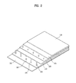
- FIG. 2 is a partially cut-away perspective view illustrating various parts provided between the inner case and the outer case;
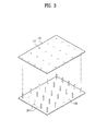
- FIG. 3 is a perspective view illustrating an assembling process of a first support plate, spacers and a second support plate shown in FIG. 2 ;
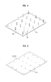
- FIG. 4 is a perspective view illustrating distance keeping members provided between some of the spacers formed in the first support plate of FIG. 2 ;
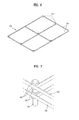
- FIG. 5 is a perspective view illustrating the radiation blocking film of FIG. 2 ;
- FIG. 6 is a perspective view illustrating sets of distance keeping members integrally connected with each other
- FIG. 7 is a perspective view illustrating a set of distance keeping members provided in one spacer
- FIG. 8 is a sectional view illustrating one distance keeping member and a set of distance keeping members provided in one spacer
- FIG. 9 is a perspective view illustrating a relative position of the set of the distance keeping members with respect to the spacer, seen above;
- FIG. 10 is a partially cut-away sectional view of various parts provided between the inner case and the outer case;
- FIG. 11 is a perspective view illustrating a state where the first support plate, the spacers and the second support plate are assembled to each other;
- FIG. 12 is a perspective view illustrating a first support plate according to another embodiment.
- FIG. 13 is a perspective view illustrating a first support plate according to a further embodiment.
- FIG. 1 illustrates a refrigerator according to one embodiment of the present invention.
- FIG. 2 is a partially cut-away perspective view illustrating various parts provided between the inner case and the outer case.
- the refrigerator includes a case 1 in which a storage chamber is formed, a first door 4 rotatably coupled to a left side of the case 1 and a second door 5 rotatably coupled to right side of the case 1.
- the first door 4 is configured to open and close a freezer compartment that consists of the storage compartment and the second door 5 is configured to open and close a refrigerator compartment that consists of the storage compartment.
- the present invention may include various types of refrigerator.
- the refrigerator shown in FIG. 1 is a side-by-side type having a refrigerator compartment arranged on the left and a freezer compartment arranged on the right.
- the refrigerator according to the present invention may be all types of refrigerators no matter how the refrigerator and freezer compartments are arranged.
- the refrigerator may be a refrigerator only having a refrigerator or freezer compartment or a refrigerator having an auxiliary cooler compartment rather than the freezer and refrigerator compartments.
- the refrigerator according to the present invention includes an inner case 110 in which the storage space is formed, an outer case 120 accommodating the inner case, spaced apart a predetermined distance from the inner case, and a vacuum space 130 provided between the inner case and the outer case, with being closed to maintain a vacuum state to perform the insulation function between the inner case and the outer case.
- one or more radiation blocking film 210 and 220 may be provided in the vacuum space 130, spaced apart a predetermined distance from the inner and outer cases.
- the radiation blocking film is configured to reduce radiant heat transferred via the vacuum space.
- the outer case 120 is spaced apart a predetermined distance from the inner case 110. No auxiliary insulating material is provided in a space formed between the outer case 120 and the inner case 110 and the space is maintained in a vacuum state to perform insulation.
- the vacuum space 130 is formed between the outer case 120 and the inner case 110, to remove a medium that delivers the heat between the cases 110 and 120.
- the heat from the hot air outside the outer case 120 can be prevented from being transmitted to the inner case as it is.
- FIG. shows that the inner case 110, the outer case 120 and spacers 150, in a state where a first support plate 160, a second support plate 170 and the radiation blocking films 210 and 220 are omitted.
- the one or more radiation blocking film 210 and 220 is provided in the vacuum space 130 to reduce the heat transfer generated by radiation, spaced apart from the inner and outer cases.
- the one or more radiation blocking film 210 and 220 may be arranged distant from the outer case 120 and the inner case 110.
- Such the radiation blocking film 210 and 220 is a metal thin film having a low emissivity configured to cut off radiant heat transfer.
- the radiation blocking film 210 and 220 configured of a metal thin film is arranged in the vacuum space 130 distant from the outer case 120 and the inner case 110.
- the radiation blocking film 210 and 220 is formed of an aluminum thin film.
- the price of such aluminum is relatively low, compared with that of silver or copper.
- the manufacturing cost is low and the emissivity is substantially similar to that of the conventional coating or plating of silver or copper.
- the thickness of the radiation blocking film 210 and 220 may be 0.05 ⁇ 0.30mm.
- the radiation blocking films 210 and 220 can be arranged distant from the outer case 120 and the inner case 110, respectively, and they should have a predetermined strength to endure deformation generated by the weight or external shock.
- the shape of the radiation blocking film can be maintained by the spacers 150 which will be described later, when the radiation blocking film has the thickness of 0.05 ⁇ 0.30mm.
- a plurality of the spacers 150 may be arranged to maintain the distance between the inner case 110 and the outer case 120 to make the vacuum space 130 maintain its profile. Such spacers 150 may support the first support plate to maintain the distance between the inner case 110 and the outer case 120.
- the plurality of the spacers 150 may be fixed between the inner case 110 and the outer case 120.
- the plurality of the spacers 150 may be arranged in the first support plate 160 as a fixing structure.
- the first support plate 160 may be provided in contact with one of facing surfaces possessed by the inner and outer cases 110 and 120.
- the first support plate 160 is arranged to contact with an outer surface of the inner case 110.
- the first support plate 160 may be arranged to contact with an inner surface of the outer case 120.
- the case 1 may further include a second support plate 170 provided in the other one of facing surfaces possessed by the first and second cases 110 and 120, with facing the first support plate.
- the second support plate 170 is arranged to contact with the inner surface of the outer case 20 and the spacers 150 are fixedly arranged in the first support plate 160 to maintain a distance spaced apart between the first support plate 160 and the second support plate 170.
- the first support plate 160 is in contact with the outer surface of the inner case 110 and the second support plate 170 is in contact with the inner surface of the outer case 120. Accordingly, the spacers 150 supportably maintain the distance between the inner case 110 and the outer case 120.
- the second support plate 170 is spaced apart a predetermined distance from the first support plate 160.
- first support plate 160 where the spacers 150 are integrally fixed may be provided between the inner case 110 and the second case 120.
- ends of the spacers 150 may be arranged to directly contact with the inner surface of the outer case 120.
- FIG. 1 shows only the inner case 110, the outer case 120 and the spacers 150, without the first support plate 160 and the second support plate 170.
- the vacuum space 130 has to be formed between the inner and outer cases 110 and 120 composing the case 1.
- rim portions of the inner and outer cases 110 and 120 that form one surface of the case 1 have to be integrally formed with each other, with the corresponding size to the size of the one surface.
- first and second support plate units are fabricated, with a smaller size than the size of the inner or outer case 110 or 120. After that, sets of assembled first and second support plates having the spacers 150 positioned there between are fabricated and the sets of the assembled plates are inserted between the inner case 110 and the outer case 120.
- first support plate 160 and the second support plate 170 are fabricated and assembled, with the same size as the inner and outer cases 110 and 120.
- FIG. 2 partially illustrates the assembling structure between the inner case 110 and the outer case 120 in a multilayered structure.
- the assembled structures from the first support plate 160 to the second support plate 170 are substantially multilayered between the inner case 110 and the outer case 120.
- FIG. 3 is a perspective view illustrating an assembling process of a first support plate, spacers and a second support plate shown in FIG. 2 .
- FIG. 4 is a perspective view illustrating distance keeping members provided between some of the spacers formed in the first support plate of FIG. 2 .
- FIG. 5 is a perspective view illustrating the radiation blocking film of FIG. 2 .
- the second support plate 170 may include a plurality of grooves formed in an inner surface thereof to insert ends of the spacers therein, respectively.
- the plurality of the grooves 175 formed in the second support plate 170 may facilitate the fixing of relative position with respect to the spacers 150, when the second support plate 170 is placed on the spacers 150 integrally formed with the first support plate 160.
- the radiation blocking film includes a plurality of through-holes 215 formed to pass the plurality of the spacers there through, respectively.
- the plurality of the spacers 150 may pass through the through-holes 215 and the through-holes may be formed at positions corresponding to the spacers, respectively.
- the through-holes 215 are correspondingly aligned in vertical and horizontal lines.
- a plurality of distance keeping members 250 may be provided in a predetermined number of the spacers 150 to keep a distance between the first support plate 160 and the radiation blocking film 210 and a distance between the radiation blocking film 210 and the second support plate 170, respectively.
- the distance keeping members 250 may be provided in the spacers 150, respectively. However, the radiation blocking film 210 formed of a metal thin film with a predetermined thickness will not come down because of its metal properties. It is preferred that the distance keeping members 250 are arranged in a predetermined number of the spacers 150.
- the distance keeping members 250 are provided in the spacers 150, respectively, heat is likely conducted via the spacers 150 and the distance keeping members 250. Accordingly, it is more preferred that the distance keeping members 250 are provided in only the predetermined number of the spacers 150.
- Two radiation blocking films 210 and 220 are provided in the vacuum space 130 in parallel, spaced apart a predetermined distance from each other.
- the distance keeping members 250 may be provided in one surface and the other opposite surface of the radiation blocking films 210 and 220, respectively.
- the structures including the first support plate 160, the second support plate 170 and the spacers and the two radiation blocking films 210 and 220 arranged between the first support plate 160 and the second support plate 170.
- the spacers 150 are integrally formed with a surface of the first support plate 160, being projected in lines vertically and horizontally.
- the distance keeping members 250 may be arranged to be inserted in the predetermined number of the spacers 150 formed in the first support plate 160.
- the distance keeping members 250 may be bosses having a predetermined height arranged on outer circumferences of the spacers 150.
- the distance keeping member 250 integrally formed with the space 150 is arranged between the first support plate 160 and the first radiation blocking film 210 disposed on the first support plate 160.
- the distance keeping member 250 is a boss type inserted in the outer circumferential surface of the space 150, namely, a hollow cylinder type. Accordingly, the distance keeping member 250 may be larger than or identical to a diameter of the space 150.
- the spacers 150 have to pass through the through-holes 215 formed in the radiation blocking film 210 and 220, respectively, such that a diameter of the through-hole 215 may be larger than or identical to the spacer 150.
- the diameter of the through hole 215 formed in the radiation blocking film 210 and 220 may be larger than the diameter of the space 150 and smaller than an external diameter of the distance keeping member 250.
- the spacer 150 may pass the through hole 125 and the radiation blocking film 210 may be supported by an upper surface of the distance keeping member 250.
- the radiation blocking film 210 and 220 may not contact with the spacer 150, to prevent heat transfer generated by conduction. It is preferred that the diameter of the through hole 215 is identical to the external diameter of the spacer 150.
- a set of distance keeping members350 arranged between the pair of the radiation blocking films 210 and 220 may be connected with each other by connection ribs 354.
- sets of distance keeping members 450 arranged between the second radiation blocking film 220 and the second support plate 170 may be connected with each other by connection ribs 454.
- the sets of the distance keeping members 350 and 450 may be formed in the same shape.
- FIG. 6 is a perspective view illustrating sets of distance keeping members integrally connected with each other.
- FIG. 7 is a perspective view illustrating a set of distance keeping members provided in one spacer.
- FIG. 8 is a sectional view illustrating one distance keeping member 250 and a set of distance keeping members 350 and 450 that are provided in one spacer.
- the first set of the distance keeping members 350 includes a plurality of distance keeping members 352 arranged in vertical or horizontal lines and connection ribs 354 integrally provided in sides of the distance keeping members 352.
- the set of the first distance keeping members 350 may have 9 distance keeping members connected with each other by 12 connection ribs 354.
- the number of the distance keeping members and connection ribs that form one set of the distance keeping members may be determined different from what is shown in FIG. 6 . For instance, 16 distance keeping members are integrally connected with each other 24 connection ribs.
- one set of the distance keeping members 350 arranged between the pair of the radiation blocking films 210 and 220 may be independently provided from the sets of the distance keeping members arranged between the second radiation blocking film 220 and the second support plate 170.
- the distance keeping members 250 are combined and assembled with the first set of the first distance keeping members 350 and the second set of the distance keeping members 450.
- Inner surfaces of the distance keeping members 352 and 452 may be inclined to reduce the heat transfer by reducing contact with the spacers 150.
- inner surfaces of the distance keeping member 352 composing the set of the first distance keeping members 350 and of the distance keeping members 452 composing the set of the second distance keeping members 450 may be getting inclined along a downward direction to make diameters of the distance keeping members 352 and 452 smaller along a downward direction.
- each distance keeping member 352 and 452 Only the lowest portion of the inner surface of each distance keeping member 352 and 452 is in contact with the spacer 150. Accordingly, the amount of the conducted heat transferred to the distance keeping members 352 and 452 from the spacers 150 can be reduced as much as possible.
- the lowest one of three distance keeping members shown in FIG. 8 (namely, the distance keeping member 250) has an outer surface inclined along a downward direction to make a diameter thereof getting smaller along a downward direction, not an inclined inner surface.
- an inclined shape of the distance keeping member 250 should be the reverse of the inclined shape shown in FIG. 8 . That is because the contact area between the second support plate 170 and the distance keeping member 250 has to be minimized.
- an inner surface of the distance keeping member 250 may be inclined to make a diameter of the distance keeping member 250 getting smaller along a downward direction.
- the inclination direction may be formed to make the inner surface of the distance keeping member 250 getting smaller along an upward direction.
- Inclination direction of other distance keeping members 352 and 452 may be formed along an upward direction as well as a downward direction.
- Inclination directions of three distance keeping members 250, 352 and 452 may be differentiated before three distance keeping members are assembled to each other.
- connection ribs 354 and 454 integrally formed with the set of the distance keeping members 350 and 450 may be not in contact with the spacers, 150, the radiation blocking films 210 and 220 and the second support plate 170.
- connection ribs 354 and 454 lower than the distance keeping members 352 and 452 are connected to middle portion of the distance keeping members 352 and 452.
- connection ribs 354 and 454 are formed not to be in contact with the radiation blocking films 210 and 220 or the second support plate 160, only to reduce the heat transfer generated by conduction as much as possible.
- connection ribs 354 of the set of the distance keeping members 350 and 450 may be arranged not to be in contact with a neighboring spacer 150 arranged nearby.
- the set of the distance keeping members may be insertedly assembled to the plurality of the spacers 150 and also the heat transfer generated by conduction may be minimized.
- FIG. 2 In a perspective of FIG. 2 and a sectional view of FIG. 20, the inner case 110, the outer case 120 and the component parts insertedly assembled between the inner case 110 and the outer case are shown.
- the independently fabricated distance keeping members 250 are inserted in the predetermined number of the spacers 150 integrally formed with the first support plate 160.
- one radiation blocking film 210 shown in FIG. 5 insertedly passes the through-holes 215. At this time, the radiation blocking film 210 is seated on top surfaces of the distance keeping members 250.
- the set of the first distance keeping members 350 is inserted in the spacers 150 to be seated on the radiation blocking film 210.
- the second radiation blocking film 220 is inserted to enable the spacers 150 to pass through the through-holes.
- the set of the second distance keeping members 450 is inserted to be seated on the radiation blocking film 220.
- the second support plate 170 is disposed to enable the ends of the spacers 150 inserted in the grooves 175 of the second support plate 170.
- the spacer set assembly with the radiation blocking film assembled as mentioned above may be inserted in the vacuum space 130 formed between the inner case 110 and the outer case 120.
- a plurality of spacer set assemblies may be required to fill the vacuum space 130.
- a predetermined number of spacer set assemblies are continuously inserted in the vacuum space 130 and the assembly process of the refrigerator is completed.
- FIG. 3 is a perspective view illustrating an assembling process of a first support plate, spacers and a second support plate.
- FIG. 11 is a perspective view illustrating a state where the first support plate, the spacers and the second support plate are assembled to each other.
- the spacers 150 may be aligned in vertical and horizontal lines.
- the plurality of the spacers 150 integrally formed with the first support plate 160 may be arranged in upward/downward and rightward/leftward lines, as shown in FIG. 5 .
- the plurality of the spacers 150 arranged in lines facilitates not only the design and molding fabrication process but also the assembly process.
- the plurality of the spacers arranged in lines may make the strength and rigidity stronger which endures the vacuum pressure or an external shock after the assembly process.
- each spacer 150 may be concavely curved.
- ends of the spacers 150 are concavely curved. In the assembly process, the end of each spacer 150 is easily seated in each groove 175 formed in the second support plate 170, only to ease the assembling work.
- the plurality of the grooves 175 formed in the second support plate 170 are convexly curved, corresponding to the shape of the spacers 150.
- the shapes of the grooves 175 formed in the second support plate 170 may be corresponding to the shapes of the spacers 150. Accordingly, it is easy to determine the positions of the spacers in the assembling work and the second support plate 170 can be fixed in parallel with the ends of the spacers, without movement.
- the spacers 150, the first support plate 160 and the second support plate 170 may be formed of one of metal, ceramic and reinforced plastic.
- the spacers 150 are provided in the vacuum space 130 formed between the inner case 110 and the outer case 120.
- the first support plate 160 and the second support plate 170 are in contact with the inner case 110 and the outer case 120, respectively.
- the heat transfer from the outside of the outer case 120 into the inside of the inner case 110 has to be reduced as much as possible.
- External heat might be conducted via the second support plate 170, the spacers 150 and the first support plate 160.
- the spacers 150, the first support plate 160 and the second support plate 170 provided between the inner case 110 and the outer case 120, in contact are formed of one of metal, ceramic and reinforced plastic with a low heat conductivity.
- the spacers and the like had better be formed of a material with a low heat conductivity and a good strength. It is more preferred that the above-mentioned components are formed of ceramic or reinforced plastic, not metal with a good strength but a relatively high heat conductivity.
- the case 1 may further include a metal coated part provided in at least predetermined portion of an outer surface of the first support plate 160 and an inner surface of the second support plate 170, to cut off radiant heat transfer.
- the metal coated part is a metal coated layer on an outer surface of the first support plate 160 or an inner surface of the second support plate 170, and it is configured to reduce the radiant heat transfer between the inner case 110 and the outer case 120.
- the metal has a good radiant heat transfer blocking property. Although it has a relatively high heat conductivity, the metal can be coated to minimize the radiant heat transfer.
- the metal coated part is provided on both the outer surface of the first support pate 160 and the inner surface of the second support plate 170 to minimize the radiant heat transfer.
- the spacers 150 are integrally formed with a first support plate 260 according to a second embodiment of the present invention.
- the second support plate 260 includes a plurality of holes formed in an edge part of the first support plate 260 between the spacers 150.
- the holes 262 form empty spaces in the first support plate 260.
- the reason why the holes 262 are formed in the first support plate 260 is that an outgassing phenomenon has to be prevented.
- Such an outgassing phenomenon means that fine atoms or molecules are leaked from a surface of the first support plate 260 positioned in the vacuum space 130 by the vacuum pressure.
- a surface area of the first support plate 260 is reduced to reduce the material itself which can generate the outgassing.
- the holes 262 are formed in the first support plate 260. Accordingly, the cost of material used in forming the first support plate can be reduced and the weight of the first support plate can be reduced.
- the spacers 150 are arranged in vertical and horizontal lines and four vertexes of one hole 262 are arranged to form a rectangle positioned adjacent to one space 150.
- the shape of the hole is not limited to such a rectangle and it may be a hexagon, octagon, oval and so on.
- the holes 262 should not interfere with the spacers 150, with a sufficient strength when the first support plate 160 supports the spacers 150.
- the holes 262 formed in the first support plate 160 are arranged in an edge part 261 of the first support plate 160.
- a first rib for connecting two spacers 150 in a horizontal direction and a second rib for connecting two spacers 150 in a vertical direction may be formed between each two of the holes 262.
- the spacers 150 may be arranged at intersection points between the first ribs 263 and the second ribs 264 or between the ribs and the edge part 261, respectively.
- the edge part 261 of the first support plate 160 may have a larger width than the second rib 263 and the second rib 264 do.
- Such the edge part 261 is employed to form an overall frame of the first support plate 160 and to provide a basic strength to the first support plate 160.
- the second support plate 170 may include a plurality of holes, like the first support plate 160 shown in FIG. 12 .
- the second support plate 170 may have a shape identical to the shape of the first support plate 260.
- the plurality of the grooves 175 mentioned above may be formed in the second support plate 170.
- FIG. 13 shows a first support plate 360 according to a third embodiment of the present invention where spacers 150 are integrally formed.
- the first support plate 360 further include a reinforcing rib365 provided in the hole 362 surrounded by ribs 363 and 364 to connect two or more spacers 150 with each other.
- the first support plate 360 includes an edge part 361, holes 362 formed in areas surrounded by the spacers arranged along the edge part 361, a plurality of first ribs 363 for connecting the spacers in a first direction in the holes and a plurality of second ribs 364 for connecting the spacers in a second direction in the holes, with crossing the plurality of the second ribs.
- the first support plate 160 may further include a plurality of reinforcing ribs 365 provided between the first ribs and the second ribs to connect the spacers with each other.
- the holes 362 form rectangles formed in the areas surrounded by the spacers 150 arranged along the edge part 361.
- the rectangles defined by virtual outlines except the ribs 363, 364 and 365 may be the holes.
- the first support plate 360 according to the third embodiment is identical to the first support plate 260 according to the second embodiment, except the reinforcing ribs 365.
- Such a reinforcing rib is configured to connect two of the spacers 150 arranged in a diagonal direction. Two of the reinforcing ribs cross each other at a middle portion.
- any types of reinforcing ribs may be applicable only if they are capable of reinforcing the strength of the first support plate 360 which the spacers 150 are integrally formed with.
- Such types include reinforcing ribs connected with the first ribs 363 or the second rib 364 in parallel.
- the first support plate 160, 260 or 360 and the second support plate 170 are integrally formed with each other, even when they are any types. Accordingly, it is preferred that the first support plate and the second support plate are fabricated in a molding frame formed in a predetermined shape one time.
- the refrigerator described above it is very easy to insertedly assemble the spacers between the inner case and the outer case. Also, the structure of the refrigerator can endure the vacuum pressure of the vacuum space sufficiently and the vacuum space can reduce the radiant heat transferred via the vacuum space as much as possible, such that the refrigerator may have an excellent insulation performance.
Landscapes
- Engineering & Computer Science (AREA)
- Chemical & Material Sciences (AREA)
- Combustion & Propulsion (AREA)
- Physics & Mathematics (AREA)
- Mechanical Engineering (AREA)
- Thermal Sciences (AREA)
- General Engineering & Computer Science (AREA)
- Refrigerator Housings (AREA)
Applications Claiming Priority (2)
| Application Number | Priority Date | Filing Date | Title |
|---|---|---|---|
| KR1020110113413A KR101898488B1 (ko) | 2011-11-02 | 2011-11-02 | 진공 공간부를 구비하는 냉장고 |
| KR1020110113414A KR101861830B1 (ko) | 2011-11-02 | 2011-11-02 | 진공 공간부를 구비하는 냉장고 |
Publications (3)
| Publication Number | Publication Date |
|---|---|
| EP2589906A2 true EP2589906A2 (de) | 2013-05-08 |
| EP2589906A3 EP2589906A3 (de) | 2017-05-17 |
| EP2589906B1 EP2589906B1 (de) | 2024-01-10 |
Family
ID=47225870
Family Applications (1)
| Application Number | Title | Priority Date | Filing Date |
|---|---|---|---|
| EP12007269.9A Active EP2589906B1 (de) | 2011-11-02 | 2012-10-22 | Kühlschrank |
Country Status (3)
| Country | Link |
|---|---|
| US (5) | US9528749B2 (de) |
| EP (1) | EP2589906B1 (de) |
| CN (1) | CN103090616B (de) |
Families Citing this family (36)
| Publication number | Priority date | Publication date | Assignee | Title |
|---|---|---|---|---|
| KR102466469B1 (ko) | 2015-08-03 | 2022-11-11 | 엘지전자 주식회사 | 진공단열체 및 냉장고 |
| KR102525551B1 (ko) * | 2015-08-03 | 2023-04-25 | 엘지전자 주식회사 | 진공단열체 및 냉장고 |
| KR102442973B1 (ko) | 2015-08-03 | 2022-09-14 | 엘지전자 주식회사 | 진공단열체 및 냉장고 |
| KR102502160B1 (ko) | 2015-08-03 | 2023-02-21 | 엘지전자 주식회사 | 진공단열체 및 냉장고 |
| KR102456642B1 (ko) | 2015-08-03 | 2022-10-19 | 엘지전자 주식회사 | 진공단열체 및 냉장고 |
| KR20170016188A (ko) | 2015-08-03 | 2017-02-13 | 엘지전자 주식회사 | 진공단열체 및 냉장고 |
| KR102529852B1 (ko) | 2015-08-03 | 2023-05-08 | 엘지전자 주식회사 | 진공단열체 및 냉장고 |
| KR102447245B1 (ko) | 2015-08-03 | 2022-09-27 | 엘지전자 주식회사 | 진공단열체 및 냉장고 |
| KR102529853B1 (ko) | 2015-08-03 | 2023-05-08 | 엘지전자 주식회사 | 진공단열체, 진공단열체의 제조방법, 다공성물질패키지, 및 냉장고 |
| KR102525550B1 (ko) | 2015-08-03 | 2023-04-25 | 엘지전자 주식회사 | 진공단열체 및 냉장고 |
| WO2017023094A1 (en) | 2015-08-03 | 2017-02-09 | Lg Electronics Inc. | Vacuum adiabatic body and refrigerator |
| KR102497139B1 (ko) * | 2015-08-03 | 2023-02-07 | 엘지전자 주식회사 | 진공단열체 |
| KR102498210B1 (ko) | 2015-08-03 | 2023-02-09 | 엘지전자 주식회사 | 진공단열체 및 냉장고 |
| KR102466470B1 (ko) | 2015-08-04 | 2022-11-11 | 엘지전자 주식회사 | 진공단열체 및 냉장고 |
| DE102015217566A1 (de) * | 2015-09-15 | 2017-03-16 | BSH Hausgeräte GmbH | Kältegerät mit einem Eisbehälter |
| KR20180090055A (ko) * | 2017-02-02 | 2018-08-10 | 엘지전자 주식회사 | 진공단열체 및 냉장고 |
| KR102449175B1 (ko) | 2017-08-01 | 2022-09-29 | 엘지전자 주식회사 | 진공단열체 및 냉장고 |
| KR102449177B1 (ko) | 2017-08-01 | 2022-09-29 | 엘지전자 주식회사 | 진공단열체 및 냉장고 |
| KR102459784B1 (ko) * | 2017-08-01 | 2022-10-28 | 엘지전자 주식회사 | 진공단열체 및 냉장고 |
| KR102427466B1 (ko) | 2017-08-01 | 2022-08-01 | 엘지전자 주식회사 | 차량, 차량용 냉장고, 및 차량용 냉장고의 제어방법 |
| KR102529116B1 (ko) | 2017-08-01 | 2023-05-08 | 엘지전자 주식회사 | 진공단열체, 진공단열체의 제작방법, 및 그 진공단열체로 단열하는 냉온장고 |
| KR102459786B1 (ko) * | 2017-08-16 | 2022-10-28 | 엘지전자 주식회사 | 진공단열체 및 냉장고 |
| US11397037B2 (en) * | 2017-10-24 | 2022-07-26 | Electrolux Home Products, Inc. | Refrigeration appliance with slim ice maker |
| KR102466448B1 (ko) | 2017-12-13 | 2022-11-11 | 엘지전자 주식회사 | 진공단열체 및 냉장고 |
| KR102511095B1 (ko) | 2017-12-13 | 2023-03-16 | 엘지전자 주식회사 | 진공단열체 및 냉장고 |
| KR102466446B1 (ko) * | 2017-12-13 | 2022-11-11 | 엘지전자 주식회사 | 진공단열체 및 냉장고 |
| KR102568737B1 (ko) | 2017-12-13 | 2023-08-21 | 엘지전자 주식회사 | 진공단열체 및 냉장고 |
| KR102530909B1 (ko) | 2017-12-13 | 2023-05-11 | 엘지전자 주식회사 | 진공단열체 및 냉장고 |
| KR102690964B1 (ko) * | 2018-06-27 | 2024-08-02 | 엘지전자 주식회사 | 진공단열체 및 냉장고 |
| KR102608948B1 (ko) * | 2018-06-27 | 2023-12-04 | 엘지전자 주식회사 | 진공단열체 및 냉장고 |
| US10697696B1 (en) | 2019-02-25 | 2020-06-30 | Whirlpool Corporation | Vacuum insulated structure with internal airway system |
| CN112556294B (zh) * | 2019-09-25 | 2023-12-22 | 博西华电器(江苏)有限公司 | 加热装置及包括其的冰箱 |
| CN111829250A (zh) * | 2020-06-15 | 2020-10-27 | 澳柯玛股份有限公司 | 一种具有真空保温层的箱体结构及冰箱 |
| KR20220059351A (ko) * | 2020-11-02 | 2022-05-10 | 엘지전자 주식회사 | 진공단열체 및 냉장고 |
| KR20220059335A (ko) * | 2020-11-02 | 2022-05-10 | 엘지전자 주식회사 | 진공단열체 및 냉장고 |
| KR20230038046A (ko) | 2021-09-10 | 2023-03-17 | 삼성전자주식회사 | 냉장고 |
Family Cites Families (58)
| Publication number | Priority date | Publication date | Assignee | Title |
|---|---|---|---|---|
| US1561769A (en) | 1921-10-26 | 1925-11-17 | Neual W Ballew | Vacuum-insulated container |
| US1518668A (en) | 1923-12-15 | 1924-12-09 | John D Mitchell | Refrigerator |
| US1541945A (en) | 1924-04-12 | 1925-06-16 | Joseph H Huntsman | Vacuum refrigerator |
| US1588707A (en) | 1924-07-23 | 1926-06-15 | Csiga Alexander | Vacuum ice chest |
| US1814114A (en) | 1925-11-21 | 1931-07-14 | Insulation Corp | Refrigeration system and method |
| US1747969A (en) | 1926-02-25 | 1930-02-18 | C & C Engineering Company Inc | Vacuous refrigerator and method of maintaining vacuum therein |
| US1833633A (en) | 1926-11-04 | 1931-11-24 | Bodman Walter Light | Refrigerator |
| US2000882A (en) | 1928-09-07 | 1935-05-07 | Stator Refrigeration Inc | Insulating housing |
| US1770200A (en) | 1929-03-07 | 1930-07-08 | Comstock & Wescott | Building construction |
| US2053252A (en) * | 1930-11-25 | 1936-09-08 | Gen Motors Corp | Refrigerating apparatus |
| US2044600A (en) * | 1931-07-03 | 1936-06-16 | Gen Motors Corp | Refrigerating apparatus |
| US1993730A (en) * | 1931-08-18 | 1935-03-12 | Mccabe Maier Corp | Heat insulating container and material |
| US2102698A (en) * | 1932-05-27 | 1937-12-21 | Gen Motors Corp | Refrigerating apparatus |
| US2196373A (en) * | 1935-08-07 | 1940-04-09 | American Flange And Mfg Compan | Refrigerator structure and insulation therefor |
| US2773362A (en) | 1953-05-18 | 1956-12-11 | Whirlpool Seeger Corp | Refrigerators for freezing food and storage of frozen food |
| US3161265A (en) * | 1959-01-27 | 1964-12-15 | Union Carbide Corp | Vacuum panel insulation |
| US4036617A (en) | 1975-04-18 | 1977-07-19 | Cryogenic Technology, Inc. | Support system for an elongated cryogenic envelope |
| CA1106628A (en) | 1976-10-27 | 1981-08-11 | Robert B. Gelbard | High efficiency heat exchanger for refrigeration suction line/capillary tube assembly |
| US4301658A (en) | 1979-12-11 | 1981-11-24 | Koolatron Industries, Ltd. | Control circuitry for thermoelectric cooler |
| IT1144387B (it) | 1981-07-16 | 1986-10-29 | Indesit | Sistema di isolamento per un apparecchio frigorifero |
| US4526015A (en) | 1984-10-15 | 1985-07-02 | General Electric Company | Support for cryostat penetration tube |
| US4959111A (en) * | 1986-08-19 | 1990-09-25 | Whirlpool Corporation | Heavy gas-filled multilayer insulation panels and method of manufacture thereof |
| US5175975A (en) | 1988-04-15 | 1993-01-05 | Midwest Research Institute | Compact vacuum insulation |
| US5157893A (en) | 1988-04-15 | 1992-10-27 | Midwest Research Institute | Compact vacuum insulation |
| CN2033487U (zh) | 1988-08-04 | 1989-03-01 | 李芧华 | 电冰箱真空室式隔热装置 |
| US5081761A (en) | 1990-04-17 | 1992-01-21 | Rinehart Ronald K | Double wall steel tank |
| CN2226260Y (zh) | 1995-03-27 | 1996-05-01 | 张明儒 | 致冷电器绝热箱体 |
| CN2241851Y (zh) | 1995-08-28 | 1996-12-04 | 王子凯 | 保温冷藏箱 |
| CA2259665A1 (en) | 1996-07-08 | 1998-01-15 | Oceaneering International, Inc. | Insulation panel |
| NL1005962C1 (nl) * | 1997-05-02 | 1998-11-03 | Rudolf Wolfgang Van Der Pol | Vacuum isolatiepaneel. |
| US6073944A (en) | 1997-08-21 | 2000-06-13 | Moore; Larry James | School supplies transporting device |
| DK1023563T3 (da) | 1997-10-16 | 2006-03-27 | Bsh Bosch Siemens Hausgeraete | Varmeisolerende væg |
| DE19745862A1 (de) | 1997-10-16 | 1999-04-22 | Bosch Siemens Hausgeraete | Wärmeisolierende Wandung |
| JPH11315668A (ja) | 1998-05-07 | 1999-11-16 | Nippon Sheet Glass Co Ltd | ガラスパネル |
| WO2001081818A1 (en) | 2000-04-21 | 2001-11-01 | Matsushita Refrigeration Company | Heat insulation box, and vacuum heat insulation material used therefor |
| TW470837B (en) | 2000-04-21 | 2002-01-01 | Matsushita Refrigeration | Vacuum heat insulator |
| DE10029437B4 (de) | 2000-06-21 | 2005-11-17 | Heraeus Noblelight Gmbh | Infrarotstrahler und Verfahren zum Betreiben eines solchen Infrarotstrahlers |
| WO2003085339A1 (de) | 2002-04-05 | 2003-10-16 | Dometic Gmbh | Kühlschrankgehäuse |
| TW593919B (en) | 2002-05-31 | 2004-06-21 | Matsushita Refrigeration | Vacuum heat insulating material and method for producing the same, and refrigerator using the vacuum heat insulating material |
| KR100896264B1 (ko) | 2003-01-17 | 2009-05-08 | 삼성전자주식회사 | 냉장고 및 냉각장치 |
| KR100519358B1 (ko) | 2003-04-08 | 2005-10-07 | 엘지전자 주식회사 | 온수 공급을 위한 순간 가열 장치 및 이를 구비한 냉장고 |
| JP2005147591A (ja) | 2003-11-18 | 2005-06-09 | Toshiba Corp | 冷蔵庫 |
| JP2005163848A (ja) | 2003-11-28 | 2005-06-23 | Seven Seven:Kk | 真空断熱材の製造方法及び断熱容体の製造方法 |
| KR20050102449A (ko) | 2004-04-22 | 2005-10-26 | 엘지전자 주식회사 | 김치냉장고 |
| CN2720362Y (zh) | 2004-08-12 | 2005-08-24 | 白尚富 | 冰箱用内设支柱式真空隔温板 |
| CN2777463Y (zh) | 2005-02-02 | 2006-05-03 | 王犁 | 胆式真空电冰箱箱体 |
| JP2007248005A (ja) | 2006-03-17 | 2007-09-27 | Sanyo Electric Co Ltd | 冷蔵庫 |
| AT504239A1 (de) | 2006-09-27 | 2008-04-15 | Rebernik Matthias Dipl Ing Dr | Kryobehälter und verfahren zu dessen herstellung |
| US7954301B2 (en) | 2007-03-16 | 2011-06-07 | Ball Aerospace & Technologies Corp. | Integrated multilayer insulation |
| ITPN20080048A1 (it) | 2008-06-13 | 2009-12-14 | Karton Spa | "apparecchio frigorifero con cella perfezionata" |
| TWI358504B (en) | 2008-08-04 | 2012-02-21 | Inotera Memories Inc | A gas-liquid separate system and a method for sepa |
| IT1391775B1 (it) | 2008-11-17 | 2012-01-27 | Ilpea Ind Spa | Circuito di raffraddamento |
| CN101487652B (zh) | 2009-02-09 | 2011-01-05 | 中国科学技术大学 | 超静液氦恒温器 |
| KR101544453B1 (ko) | 2009-08-07 | 2015-08-13 | 엘지전자 주식회사 | 진공 단열재의 코어 및 이를 이용한 진공 단열재 |
| CN101793455A (zh) | 2010-04-08 | 2010-08-04 | 中国电子科技集团公司第十六研究所 | 一种深冷冰箱箱体 |
| KR101068459B1 (ko) | 2010-07-29 | 2011-09-28 | 주식회사엑스엘 | 진공단열패널 |
| KR101147779B1 (ko) | 2010-10-28 | 2012-05-25 | 엘지전자 주식회사 | 진공공간부를 구비하는 냉장고 |
| US8365551B2 (en) | 2010-12-09 | 2013-02-05 | General Electric Company | Vacuum insulator for a refrigerator appliance |
-
2012
- 2012-10-18 US US13/654,551 patent/US9528749B2/en active Active
- 2012-10-22 EP EP12007269.9A patent/EP2589906B1/de active Active
- 2012-11-02 CN CN201210432112.5A patent/CN103090616B/zh active Active
-
2016
- 2016-12-12 US US15/375,308 patent/US10330373B2/en active Active
-
2019
- 2019-06-19 US US16/445,425 patent/US11346594B2/en active Active
-
2022
- 2022-03-02 US US17/684,749 patent/US11732953B2/en active Active
-
2023
- 2023-07-05 US US18/347,284 patent/US12595956B2/en active Active
Non-Patent Citations (1)
| Title |
|---|
| None |
Also Published As
| Publication number | Publication date |
|---|---|
| US11732953B2 (en) | 2023-08-22 |
| US20220187010A1 (en) | 2022-06-16 |
| US20230349627A1 (en) | 2023-11-02 |
| CN103090616A (zh) | 2013-05-08 |
| US10330373B2 (en) | 2019-06-25 |
| EP2589906A3 (de) | 2017-05-17 |
| CN103090616B (zh) | 2016-06-29 |
| US20130105494A1 (en) | 2013-05-02 |
| US11346594B2 (en) | 2022-05-31 |
| US20190301788A1 (en) | 2019-10-03 |
| US9528749B2 (en) | 2016-12-27 |
| US12595956B2 (en) | 2026-04-07 |
| EP2589906B1 (de) | 2024-01-10 |
| US20170089634A1 (en) | 2017-03-30 |
Similar Documents
| Publication | Publication Date | Title |
|---|---|---|
| US11732953B2 (en) | Refrigerator | |
| US11802728B2 (en) | Refrigerator | |
| US20110095669A1 (en) | Refrigerator vacuum insulation application | |
| KR101898488B1 (ko) | 진공 공간부를 구비하는 냉장고 | |
| KR20130048528A (ko) | 진공 공간부를 구비하는 냉장고 | |
| KR102123614B1 (ko) | 진공 공간부를 구비하는 냉장고 | |
| KR102639611B1 (ko) | 진공 공간부를 구비하는 냉장고 | |
| KR102825924B1 (ko) | 진공 공간부를 구비하는 냉장고 | |
| KR102257728B1 (ko) | 진공 공간부를 구비하는 냉장고 | |
| KR102011824B1 (ko) | 진공 공간부를 구비하는 냉장고 | |
| KR102310496B1 (ko) | 진공 공간부를 구비하는 냉장고 |
Legal Events
| Date | Code | Title | Description |
|---|---|---|---|
| PUAI | Public reference made under article 153(3) epc to a published international application that has entered the european phase |
Free format text: ORIGINAL CODE: 0009012 |
|
| AK | Designated contracting states |
Kind code of ref document: A2 Designated state(s): AL AT BE BG CH CY CZ DE DK EE ES FI FR GB GR HR HU IE IS IT LI LT LU LV MC MK MT NL NO PL PT RO RS SE SI SK SM TR |
|
| AX | Request for extension of the european patent |
Extension state: BA ME |
|
| RIN1 | Information on inventor provided before grant (corrected) |
Inventor name: YOUN, DEOKHYUN Inventor name: JUNG, WONYEONG |
|
| 17P | Request for examination filed |
Effective date: 20140331 |
|
| RBV | Designated contracting states (corrected) |
Designated state(s): AL AT BE BG CH CY CZ DE DK EE ES FI FR GB GR HR HU IE IS IT LI LT LU LV MC MK MT NL NO PL PT RO RS SE SI SK SM TR |
|
| PUAL | Search report despatched |
Free format text: ORIGINAL CODE: 0009013 |
|
| AK | Designated contracting states |
Kind code of ref document: A3 Designated state(s): AL AT BE BG CH CY CZ DE DK EE ES FI FR GB GR HR HU IE IS IT LI LT LU LV MC MK MT NL NO PL PT RO RS SE SI SK SM TR |
|
| AX | Request for extension of the european patent |
Extension state: BA ME |
|
| RIC1 | Information provided on ipc code assigned before grant |
Ipc: F25D 23/06 20060101AFI20170413BHEP |
|
| RIN1 | Information on inventor provided before grant (corrected) |
Inventor name: YOUN, DEOKHYUN Inventor name: JUNG, WONYEONG |
|
| STAA | Information on the status of an ep patent application or granted ep patent |
Free format text: STATUS: EXAMINATION IS IN PROGRESS |
|
| 17Q | First examination report despatched |
Effective date: 20200317 |
|
| GRAP | Despatch of communication of intention to grant a patent |
Free format text: ORIGINAL CODE: EPIDOSNIGR1 |
|
| STAA | Information on the status of an ep patent application or granted ep patent |
Free format text: STATUS: GRANT OF PATENT IS INTENDED |
|
| INTG | Intention to grant announced |
Effective date: 20230807 |
|
| RAP3 | Party data changed (applicant data changed or rights of an application transferred) |
Owner name: LG ELECTRONICS INC. |
|
| GRAS | Grant fee paid |
Free format text: ORIGINAL CODE: EPIDOSNIGR3 |
|
| GRAA | (expected) grant |
Free format text: ORIGINAL CODE: 0009210 |
|
| STAA | Information on the status of an ep patent application or granted ep patent |
Free format text: STATUS: THE PATENT HAS BEEN GRANTED |
|
| AK | Designated contracting states |
Kind code of ref document: B1 Designated state(s): AL AT BE BG CH CY CZ DE DK EE ES FI FR GB GR HR HU IE IS IT LI LT LU LV MC MK MT NL NO PL PT RO RS SE SI SK SM TR |
|
| REG | Reference to a national code |
Ref country code: GB Ref legal event code: FG4D |
|
| REG | Reference to a national code |
Ref country code: CH Ref legal event code: EP |
|
| REG | Reference to a national code |
Ref country code: DE Ref legal event code: R096 Ref document number: 602012080481 Country of ref document: DE |
|
| REG | Reference to a national code |
Ref country code: IE Ref legal event code: FG4D |
|
| REG | Reference to a national code |
Ref country code: LT Ref legal event code: MG9D |
|
| REG | Reference to a national code |
Ref country code: NL Ref legal event code: MP Effective date: 20240110 |
|
| REG | Reference to a national code |
Ref country code: AT Ref legal event code: MK05 Ref document number: 1649197 Country of ref document: AT Kind code of ref document: T Effective date: 20240110 |
|
| PG25 | Lapsed in a contracting state [announced via postgrant information from national office to epo] |
Ref country code: NL Free format text: LAPSE BECAUSE OF FAILURE TO SUBMIT A TRANSLATION OF THE DESCRIPTION OR TO PAY THE FEE WITHIN THE PRESCRIBED TIME-LIMIT Effective date: 20240110 |
|
| PG25 | Lapsed in a contracting state [announced via postgrant information from national office to epo] |
Ref country code: NL Free format text: LAPSE BECAUSE OF FAILURE TO SUBMIT A TRANSLATION OF THE DESCRIPTION OR TO PAY THE FEE WITHIN THE PRESCRIBED TIME-LIMIT Effective date: 20240110 |
|
| PG25 | Lapsed in a contracting state [announced via postgrant information from national office to epo] |
Ref country code: IS Free format text: LAPSE BECAUSE OF FAILURE TO SUBMIT A TRANSLATION OF THE DESCRIPTION OR TO PAY THE FEE WITHIN THE PRESCRIBED TIME-LIMIT Effective date: 20240510 |
|
| PG25 | Lapsed in a contracting state [announced via postgrant information from national office to epo] |
Ref country code: LT Free format text: LAPSE BECAUSE OF FAILURE TO SUBMIT A TRANSLATION OF THE DESCRIPTION OR TO PAY THE FEE WITHIN THE PRESCRIBED TIME-LIMIT Effective date: 20240110 |
|
| PG25 | Lapsed in a contracting state [announced via postgrant information from national office to epo] |
Ref country code: GR Free format text: LAPSE BECAUSE OF FAILURE TO SUBMIT A TRANSLATION OF THE DESCRIPTION OR TO PAY THE FEE WITHIN THE PRESCRIBED TIME-LIMIT Effective date: 20240411 |
|
| PG25 | Lapsed in a contracting state [announced via postgrant information from national office to epo] |
Ref country code: HR Free format text: LAPSE BECAUSE OF FAILURE TO SUBMIT A TRANSLATION OF THE DESCRIPTION OR TO PAY THE FEE WITHIN THE PRESCRIBED TIME-LIMIT Effective date: 20240110 Ref country code: RS Free format text: LAPSE BECAUSE OF FAILURE TO SUBMIT A TRANSLATION OF THE DESCRIPTION OR TO PAY THE FEE WITHIN THE PRESCRIBED TIME-LIMIT Effective date: 20240410 |
|
| PG25 | Lapsed in a contracting state [announced via postgrant information from national office to epo] |
Ref country code: ES Free format text: LAPSE BECAUSE OF FAILURE TO SUBMIT A TRANSLATION OF THE DESCRIPTION OR TO PAY THE FEE WITHIN THE PRESCRIBED TIME-LIMIT Effective date: 20240110 |
|
| PG25 | Lapsed in a contracting state [announced via postgrant information from national office to epo] |
Ref country code: AT Free format text: LAPSE BECAUSE OF FAILURE TO SUBMIT A TRANSLATION OF THE DESCRIPTION OR TO PAY THE FEE WITHIN THE PRESCRIBED TIME-LIMIT Effective date: 20240110 |
|
| PG25 | Lapsed in a contracting state [announced via postgrant information from national office to epo] |
Ref country code: RS Free format text: LAPSE BECAUSE OF FAILURE TO SUBMIT A TRANSLATION OF THE DESCRIPTION OR TO PAY THE FEE WITHIN THE PRESCRIBED TIME-LIMIT Effective date: 20240410 Ref country code: NO Free format text: LAPSE BECAUSE OF FAILURE TO SUBMIT A TRANSLATION OF THE DESCRIPTION OR TO PAY THE FEE WITHIN THE PRESCRIBED TIME-LIMIT Effective date: 20240410 Ref country code: LT Free format text: LAPSE BECAUSE OF FAILURE TO SUBMIT A TRANSLATION OF THE DESCRIPTION OR TO PAY THE FEE WITHIN THE PRESCRIBED TIME-LIMIT Effective date: 20240110 Ref country code: IS Free format text: LAPSE BECAUSE OF FAILURE TO SUBMIT A TRANSLATION OF THE DESCRIPTION OR TO PAY THE FEE WITHIN THE PRESCRIBED TIME-LIMIT Effective date: 20240510 Ref country code: HR Free format text: LAPSE BECAUSE OF FAILURE TO SUBMIT A TRANSLATION OF THE DESCRIPTION OR TO PAY THE FEE WITHIN THE PRESCRIBED TIME-LIMIT Effective date: 20240110 Ref country code: GR Free format text: LAPSE BECAUSE OF FAILURE TO SUBMIT A TRANSLATION OF THE DESCRIPTION OR TO PAY THE FEE WITHIN THE PRESCRIBED TIME-LIMIT Effective date: 20240411 Ref country code: ES Free format text: LAPSE BECAUSE OF FAILURE TO SUBMIT A TRANSLATION OF THE DESCRIPTION OR TO PAY THE FEE WITHIN THE PRESCRIBED TIME-LIMIT Effective date: 20240110 Ref country code: BG Free format text: LAPSE BECAUSE OF FAILURE TO SUBMIT A TRANSLATION OF THE DESCRIPTION OR TO PAY THE FEE WITHIN THE PRESCRIBED TIME-LIMIT Effective date: 20240110 Ref country code: AT Free format text: LAPSE BECAUSE OF FAILURE TO SUBMIT A TRANSLATION OF THE DESCRIPTION OR TO PAY THE FEE WITHIN THE PRESCRIBED TIME-LIMIT Effective date: 20240110 |
|
| PG25 | Lapsed in a contracting state [announced via postgrant information from national office to epo] |
Ref country code: PL Free format text: LAPSE BECAUSE OF FAILURE TO SUBMIT A TRANSLATION OF THE DESCRIPTION OR TO PAY THE FEE WITHIN THE PRESCRIBED TIME-LIMIT Effective date: 20240110 Ref country code: PT Free format text: LAPSE BECAUSE OF FAILURE TO SUBMIT A TRANSLATION OF THE DESCRIPTION OR TO PAY THE FEE WITHIN THE PRESCRIBED TIME-LIMIT Effective date: 20240510 |
|
| PG25 | Lapsed in a contracting state [announced via postgrant information from national office to epo] |
Ref country code: SE Free format text: LAPSE BECAUSE OF FAILURE TO SUBMIT A TRANSLATION OF THE DESCRIPTION OR TO PAY THE FEE WITHIN THE PRESCRIBED TIME-LIMIT Effective date: 20240110 Ref country code: PT Free format text: LAPSE BECAUSE OF FAILURE TO SUBMIT A TRANSLATION OF THE DESCRIPTION OR TO PAY THE FEE WITHIN THE PRESCRIBED TIME-LIMIT Effective date: 20240510 Ref country code: PL Free format text: LAPSE BECAUSE OF FAILURE TO SUBMIT A TRANSLATION OF THE DESCRIPTION OR TO PAY THE FEE WITHIN THE PRESCRIBED TIME-LIMIT Effective date: 20240110 Ref country code: LV Free format text: LAPSE BECAUSE OF FAILURE TO SUBMIT A TRANSLATION OF THE DESCRIPTION OR TO PAY THE FEE WITHIN THE PRESCRIBED TIME-LIMIT Effective date: 20240110 |
|
| PG25 | Lapsed in a contracting state [announced via postgrant information from national office to epo] |
Ref country code: DK Free format text: LAPSE BECAUSE OF FAILURE TO SUBMIT A TRANSLATION OF THE DESCRIPTION OR TO PAY THE FEE WITHIN THE PRESCRIBED TIME-LIMIT Effective date: 20240110 |
|
| REG | Reference to a national code |
Ref country code: DE Ref legal event code: R097 Ref document number: 602012080481 Country of ref document: DE |
|
| PG25 | Lapsed in a contracting state [announced via postgrant information from national office to epo] |
Ref country code: SM Free format text: LAPSE BECAUSE OF FAILURE TO SUBMIT A TRANSLATION OF THE DESCRIPTION OR TO PAY THE FEE WITHIN THE PRESCRIBED TIME-LIMIT Effective date: 20240110 |
|
| PG25 | Lapsed in a contracting state [announced via postgrant information from national office to epo] |
Ref country code: EE Free format text: LAPSE BECAUSE OF FAILURE TO SUBMIT A TRANSLATION OF THE DESCRIPTION OR TO PAY THE FEE WITHIN THE PRESCRIBED TIME-LIMIT Effective date: 20240110 Ref country code: CZ Free format text: LAPSE BECAUSE OF FAILURE TO SUBMIT A TRANSLATION OF THE DESCRIPTION OR TO PAY THE FEE WITHIN THE PRESCRIBED TIME-LIMIT Effective date: 20240110 |
|
| PG25 | Lapsed in a contracting state [announced via postgrant information from national office to epo] |
Ref country code: SK Free format text: LAPSE BECAUSE OF FAILURE TO SUBMIT A TRANSLATION OF THE DESCRIPTION OR TO PAY THE FEE WITHIN THE PRESCRIBED TIME-LIMIT Effective date: 20240110 |
|
| PG25 | Lapsed in a contracting state [announced via postgrant information from national office to epo] |
Ref country code: SM Free format text: LAPSE BECAUSE OF FAILURE TO SUBMIT A TRANSLATION OF THE DESCRIPTION OR TO PAY THE FEE WITHIN THE PRESCRIBED TIME-LIMIT Effective date: 20240110 Ref country code: SK Free format text: LAPSE BECAUSE OF FAILURE TO SUBMIT A TRANSLATION OF THE DESCRIPTION OR TO PAY THE FEE WITHIN THE PRESCRIBED TIME-LIMIT Effective date: 20240110 Ref country code: RO Free format text: LAPSE BECAUSE OF FAILURE TO SUBMIT A TRANSLATION OF THE DESCRIPTION OR TO PAY THE FEE WITHIN THE PRESCRIBED TIME-LIMIT Effective date: 20240110 Ref country code: EE Free format text: LAPSE BECAUSE OF FAILURE TO SUBMIT A TRANSLATION OF THE DESCRIPTION OR TO PAY THE FEE WITHIN THE PRESCRIBED TIME-LIMIT Effective date: 20240110 Ref country code: DK Free format text: LAPSE BECAUSE OF FAILURE TO SUBMIT A TRANSLATION OF THE DESCRIPTION OR TO PAY THE FEE WITHIN THE PRESCRIBED TIME-LIMIT Effective date: 20240110 Ref country code: CZ Free format text: LAPSE BECAUSE OF FAILURE TO SUBMIT A TRANSLATION OF THE DESCRIPTION OR TO PAY THE FEE WITHIN THE PRESCRIBED TIME-LIMIT Effective date: 20240110 |
|
| PLBE | No opposition filed within time limit |
Free format text: ORIGINAL CODE: 0009261 |
|
| STAA | Information on the status of an ep patent application or granted ep patent |
Free format text: STATUS: NO OPPOSITION FILED WITHIN TIME LIMIT |
|
| PG25 | Lapsed in a contracting state [announced via postgrant information from national office to epo] |
Ref country code: IT Free format text: LAPSE BECAUSE OF FAILURE TO SUBMIT A TRANSLATION OF THE DESCRIPTION OR TO PAY THE FEE WITHIN THE PRESCRIBED TIME-LIMIT Effective date: 20240110 |
|
| 26N | No opposition filed |
Effective date: 20241011 |
|
| PG25 | Lapsed in a contracting state [announced via postgrant information from national office to epo] |
Ref country code: IT Free format text: LAPSE BECAUSE OF FAILURE TO SUBMIT A TRANSLATION OF THE DESCRIPTION OR TO PAY THE FEE WITHIN THE PRESCRIBED TIME-LIMIT Effective date: 20240110 |
|
| PG25 | Lapsed in a contracting state [announced via postgrant information from national office to epo] |
Ref country code: SI Free format text: LAPSE BECAUSE OF FAILURE TO SUBMIT A TRANSLATION OF THE DESCRIPTION OR TO PAY THE FEE WITHIN THE PRESCRIBED TIME-LIMIT Effective date: 20240110 |
|
| REG | Reference to a national code |
Ref country code: CH Ref legal event code: PL |
|
| PG25 | Lapsed in a contracting state [announced via postgrant information from national office to epo] |
Ref country code: MC Free format text: LAPSE BECAUSE OF FAILURE TO SUBMIT A TRANSLATION OF THE DESCRIPTION OR TO PAY THE FEE WITHIN THE PRESCRIBED TIME-LIMIT Effective date: 20240110 |
|
| PG25 | Lapsed in a contracting state [announced via postgrant information from national office to epo] |
Ref country code: LU Free format text: LAPSE BECAUSE OF NON-PAYMENT OF DUE FEES Effective date: 20241022 Ref country code: BE Free format text: LAPSE BECAUSE OF NON-PAYMENT OF DUE FEES Effective date: 20241031 |
|
| PG25 | Lapsed in a contracting state [announced via postgrant information from national office to epo] |
Ref country code: CH Free format text: LAPSE BECAUSE OF NON-PAYMENT OF DUE FEES Effective date: 20241031 |
|
| REG | Reference to a national code |
Ref country code: BE Ref legal event code: MM Effective date: 20241031 |
|
| PG25 | Lapsed in a contracting state [announced via postgrant information from national office to epo] |
Ref country code: FI Free format text: LAPSE BECAUSE OF FAILURE TO SUBMIT A TRANSLATION OF THE DESCRIPTION OR TO PAY THE FEE WITHIN THE PRESCRIBED TIME-LIMIT Effective date: 20240110 |
|
| PGFP | Annual fee paid to national office [announced via postgrant information from national office to epo] |
Ref country code: GB Payment date: 20250909 Year of fee payment: 14 |
|
| PGFP | Annual fee paid to national office [announced via postgrant information from national office to epo] |
Ref country code: FR Payment date: 20250909 Year of fee payment: 14 |
|
| PG25 | Lapsed in a contracting state [announced via postgrant information from national office to epo] |
Ref country code: IE Free format text: LAPSE BECAUSE OF NON-PAYMENT OF DUE FEES Effective date: 20241022 |
|
| PGFP | Annual fee paid to national office [announced via postgrant information from national office to epo] |
Ref country code: DE Payment date: 20250908 Year of fee payment: 14 |
|
| PG25 | Lapsed in a contracting state [announced via postgrant information from national office to epo] |
Ref country code: CY Free format text: LAPSE BECAUSE OF FAILURE TO SUBMIT A TRANSLATION OF THE DESCRIPTION OR TO PAY THE FEE WITHIN THE PRESCRIBED TIME-LIMIT; INVALID AB INITIO Effective date: 20121022 |
|
| PG25 | Lapsed in a contracting state [announced via postgrant information from national office to epo] |
Ref country code: HU Free format text: LAPSE BECAUSE OF FAILURE TO SUBMIT A TRANSLATION OF THE DESCRIPTION OR TO PAY THE FEE WITHIN THE PRESCRIBED TIME-LIMIT; INVALID AB INITIO Effective date: 20121022 |