EP2589971A2 - Vorrichtung und Verfahren zur Grenztastung von elektrischem Strom - Google Patents
Vorrichtung und Verfahren zur Grenztastung von elektrischem Strom Download PDFInfo
- Publication number
- EP2589971A2 EP2589971A2 EP11194486.4A EP11194486A EP2589971A2 EP 2589971 A2 EP2589971 A2 EP 2589971A2 EP 11194486 A EP11194486 A EP 11194486A EP 2589971 A2 EP2589971 A2 EP 2589971A2
- Authority
- EP
- European Patent Office
- Prior art keywords
- conducting wire
- magnetic flux
- sensing
- electric current
- sensing unit
- Prior art date
- Legal status (The legal status is an assumption and is not a legal conclusion. Google has not performed a legal analysis and makes no representation as to the accuracy of the status listed.)
- Granted
Links
Images




Classifications
-
- G—PHYSICS
- G01—MEASURING; TESTING
- G01R—MEASURING ELECTRIC VARIABLES; MEASURING MAGNETIC VARIABLES
- G01R15/00—Details of measuring arrangements of the types provided for in groups G01R17/00 - G01R29/00, G01R33/00 - G01R33/26 or G01R35/00
- G01R15/14—Adaptations providing voltage or current isolation, e.g. for high-voltage or high-current networks
- G01R15/20—Adaptations providing voltage or current isolation, e.g. for high-voltage or high-current networks using galvano-magnetic devices, e.g. Hall-effect devices, i.e. measuring a magnetic field via the interaction between a current and a magnetic field, e.g. magneto resistive or Hall effect devices
-
- G—PHYSICS
- G01—MEASURING; TESTING
- G01R—MEASURING ELECTRIC VARIABLES; MEASURING MAGNETIC VARIABLES
- G01R15/00—Details of measuring arrangements of the types provided for in groups G01R17/00 - G01R29/00, G01R33/00 - G01R33/26 or G01R35/00
- G01R15/14—Adaptations providing voltage or current isolation, e.g. for high-voltage or high-current networks
- G01R15/146—Measuring arrangements for current not covered by other subgroups of G01R15/14, e.g. using current dividers, shunts, or measuring a voltage drop
- G01R15/148—Measuring arrangements for current not covered by other subgroups of G01R15/14, e.g. using current dividers, shunts, or measuring a voltage drop involving the measuring of a magnetic field or electric field
-
- G—PHYSICS
- G01—MEASURING; TESTING
- G01R—MEASURING ELECTRIC VARIABLES; MEASURING MAGNETIC VARIABLES
- G01R15/00—Details of measuring arrangements of the types provided for in groups G01R17/00 - G01R29/00, G01R33/00 - G01R33/26 or G01R35/00
- G01R15/14—Adaptations providing voltage or current isolation, e.g. for high-voltage or high-current networks
- G01R15/18—Adaptations providing voltage or current isolation, e.g. for high-voltage or high-current networks using inductive devices, e.g. transformers
- G01R15/181—Adaptations providing voltage or current isolation, e.g. for high-voltage or high-current networks using inductive devices, e.g. transformers using coils without a magnetic core, e.g. Rogowski coils
Definitions
- the disclosure relates to an electric current sensor, and more particularly to a proximity electric current sensing device.
- electric current sensors can be divided into four categories based on principles: 1. Ohm's law -shunting resistance, 2. Faraday's law of induction - current transformer (CT) 3. magnetic field sensing - Hall element, and 4. Faraday's photoelectric effect - optical fiber current sensor.
- the first two are either for direct measurement or bulky, and thus they are not convenient to use.
- Hall element is small and light and has a feature of proximity measurement which makes it stand out among others.
- optical fiber current sensor it is difficult to maintain and is structurally complicated and therefore is only for a narrow range of applications.
- magnetic field is formed in the surrounding when electric current goes through a conductor.
- the intensity of magnetic field is in direct proportion to an electric current of the conductor and in inverse proportion to a distance to the conductor. Therefore, an amount of electric current passes through the conductor can be known by sensing the intensity of the magnetic field.
- a proximity electric current sensing device of the disclosure comprises a main body, a first adjusting component, a second adjusting component, a first sensing unit, a second sensing unit, a third sensing unit, and a processing unit.
- the main body has a hole for a conducting wire to go through the main body.
- the first adjusting component is disposed on a first side of the main body for adjusting a first position of the conducting wire.
- the second adjusting component is disposed on a second side of the main body for adjusting a second position of the conducting wire.
- the first sensing unit is disposed on the main body and adjacent to a first side of the conducting wire for sensing a first magnetic flux of the conducting wire.
- the second sensing unit is disposed on the main body and adjacent to a second side of the conducting wire for sensing a second magnetic flux of the conducting wire.
- the third sensing unit is disposed on the main body and adjacent to a third side of the conducting wire for sensing a third magnetic flux of the conducting wire.
- the processing unit is coupled to the first sensing unit, the second sensing unit, and the third sensing unit for determining a position of the conducting wire according to the first and second magnetic flux, and calculates an amount of electric current according to the third magnetic flux.
- a proximity electric current sensing method of the disclosure includes the following steps: using the first sensing unit to sense the first magnetic flux of the conducting wire, wherein the first sensing unit is adjacent to the first side of the conducting wire; using the second sensing unit to sense the second magnetic flux of the conducting wire, wherein the second sensing unit is adjacent to the second side of the conducting wire; using the third sensing unit to sense the third magnetic flux of the conducting wire, wherein the third sensing unit is adjacent to the third side of the conducting wire; calculating the position of the conducting wire according to the first and second magnetic flux; and calculating the amount of electric current according to the third magnetic flux.
- proximity electric current sensors mostly have a problem of big measurement error caused by installation position, which makes them inconvenient in applications, therefore proximity electric current sensor can be improved for better performance.
- the disclosure provides a proximity electric current sensing device and method, by which a conducting wire's position can be precisely calibrated in order to reduce a measurement error of electric current.
- FIG. 1 is a perspective view of a proximity electric current sensing device of the disclosure.
- a proximity electric current sensing device 100 comprises a main body 110, adjusting components 120 and 130, sensing units 140, 150 and 160, a processing unit 170, and a display unit 180.
- the main body 110 has a hole 111.
- the hole 111 is for a conducting wire 112 to go through the main body 110.
- users can have the conducting wire 112 go through the main body 110 through the hole 111, in order to measure an amount of electric current of the conducting wire 112.
- the conduction wire 112 is a dual core power cord.
- the adjusting component 120 is disposed on a first side of the main body 110 for adjusting a first position of the conducting wire 112.
- the adjusting component 130 is disposed on a second side of the main body 110 for adjusting a second position of the conducting wire 112.
- the adjusting component 120 includes a bar 121 and a knob 122 connected to the bar 121, and the bar 121 performs a reciprocating motion by turning the knob 122, so that the bar 121 can be inserted into or out of the main body 110.
- the adjusting component 130 includes a bar 131 and a knob 132.
- the knob 132 is connected to the bar 131, and the bar 131 performs a reciprocating motion by turning the knob 132, so that the bar 131 can be inserted into or out of the main body 110.
- users can adjust the conducting wire 112 to move left or right horizontally with respect to the sensing unit 160 by turning the knobs 122 or 132, so that the conducting wire 112 can be adjusted to be disposed at a central position inside the main body 110 for measuring the amount of electric current of the conducting wire 112.
- the sensing unit 140 is disposed on the main body 110 and adjacent to a first side of the conducting wire 112 for sensing a first magnetic flux of the conducting wire 112.
- the first magnetic flux sensed by the sensing unit 140 has a larger intensity if the conducting wire 112 is disposed nearer to the sensing unit 140. On the contrary, the first magnetic flux sensed by the sensing unit 140 has a smaller intensity if the conducting wire 112 is disposed further from the sensing unit 140.
- the sensing unit 150 is disposed on the main body 110 and adjacent to a second side of the conducting wire 112 for sensing a second magnetic flux of the conducting wire 112.
- the second magnetic flux sensed by the sensing unit 150 has a larger intensity if the conducting wire 112 is disposed nearer to the sensing unit 150.
- the second magnetic flux sensed by the sensing unit 150 has a smaller intensity if the conducting wire 112 is disposed further from the sensing unit 150.
- the sensing unit 160 is disposed on the main body 110 and adjacent to a third side of the conducting wire 112 for sensing a third magnetic flux of the conducting wire 112.
- the processing unit 170 is coupled to the sensing units 140, 150 and 160 for determining the position of the conducting wire 112 according to the first magnetic flux and the second magnetic flux, and calculates an amount of electric current flowed through the conducting wire 112 according to the third magnetic flux. Furthermore, the processing unit 170 estimates the installation position of the conducting wire 112, i.e., a distance between the conducting wire 112 and the sensing unit 160, according to the third magnetic flux.
- the display unit 180 is coupled to the processing unit 170 for displaying the position of the conducting wire 112 and the amount of electric current flowing through the conducting wire 112.
- the position of the conducting wire 112 is offset according to the position of the conducting wire 112 displayed by the display unit 180, in order to observe if the sensing unit 160 is right above the center of the conducting wire 112, i.e., if the conducting wire 112 is at the central position inside the main body 110. If the conducting wire 112 is not at the central position inside the main body 110, then, the position of the conducting wire 112 is adjusted by the adjusting components 120 and 130 to ensure that the sensing unit 160 is right above the center of the conducting wire 112, so that a measurement error of electric current can be reduced.
- Fig. 2 illustrates a disposition of the sensing units 140, 150 and 160 of the disclosure.
- the sensing units 140 and 150 can be sensing coils.
- the sensing unit 160 further includes sensing coils 210 and 220.
- the sensing coil 210 is disposed on the main body 110 and adjacent to the third side of the conducting wire 112.
- the sensing coil 220 is disposed on the main body 110 at a preset distance d adjacent to the sensing coil 210.
- the preset distance d is a known and fixed distance.
- values of I and g can be acquired based on the abovementioned two equations, so that the amount of the electric current of the conducting wire 112 and the installation position of the conducting wire 112 (i.e. the distance between the conducting wire 112 and the sensing unit 160) can be precisely sensed by the proximity electric current sensing device 100 of this embodiment.
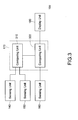
- Fig. 3 is a block diagram of a circuit of a proximity electric current sensing device of the disclosure.
- the proximity electric current sensing device 100 comprises the sensing units 140, 150 and 160, the processing unit 170 and the display unit 180. Their coupling relationships can be referred to Fig. 3 , which will not be mentioned again herein.
- the processing unit 170 includes a comparing unit 310 and a computing unit 320.
- the comparing unit 310 is coupled to the sensing units 140 and 150 for receiving and comparing the first magnetic flux and the second magnetic flux in order to generate a first comparison result.
- the computing unit 320 is coupled to the comparing unit 310 and the sensing unit 160 for determining the position of the conducting wire 112 according to the first comparison result, and calculating the amount of electric current flowing through the conducting wire 112 according to the third magnetic flux.
- the comparing unit 310 when the first magnetic flux is larger than the second magnetic flux, the comparing unit 310 outputs, for example, a positive value as the first comparison result, then the computing unit 320 determines that the position of the conducting wire 112 is nearer to the sensing unit 140, which will be displayed on the display unit 180.
- the comparing unit 310 outputs, for example, a negative value as the first comparison result, then the computing unit 320 determines that the position of the conducting wire 112 is nearer to the sensing unit 150, which will be displayed on the display unit 180.
- the comparing unit 310 When the first magnetic flux is equal to the second magnetic flux, the comparing unit 310 outputs, for example, a zero value as the first comparison result, then the computing unit 320 determines that the position of the conducting wire 112 is between the sensing unit 140 and the sensing unit 150, and in the central position inside the main body 110, which will be displayed on the display unit 180.
- the processing unit 170 determines the position of the conducting wire 112 which is displayed on the display unit 180. If the position of the conducting wire 112 is nearer to the sensing unit 140, users can adjust the conducting wire 112 to the left using the adjusting component 120, so that the conducting wire 112 is moved away from the sensing unit 140 towards the sensing unit 150.
- the users can adjust the conducting wire 112 to the right by using the adjusting component 130, so that the conducting wire 112 is moved away from the sensing unit 150 towards the sensing unit 140.
- the position of the conducting wire 112 will be disposed at the central position inside the main body 110.
- the third magnetic flux of the conducting wire 112 is sensed by the sensing unit 160, and the sensed third magnetic flux is calculated by the processing unit 170 according to aforementioned Faraday's laws, so that the electric current flowing through the conducting wire 112 can be acquired. Thereby, the electric current of the conducting wire 112 can be measured precisely, so that a measurement error of the electric current can be reduced.
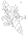
- FIG. 4 is a diagram of a proximity electric current sensing device of another embodiment of the disclosure.
- a proximity electric current sensing device 400 comprises a main body 410, adjusting components 420, 430, 440 and 450, sensing units 462, 464, 466 and 468, a processing unit 470, and a display unit 480.
- the main body 410 has a hole 411.
- the hole 411 is used for a conducting wire 412 to go through the main body 410.
- users can have the conducting wire 412 go through the main body 410 through the hole 411, in order to measure an amount of electric current of the conducting wire 412.
- the conducting wire 412 is a dual core power cord.
- the adjusting component 420 is disposed on a first side of the main body 410 for adjusting a first position of the conducting wire 412.
- the adjusting component 430 is disposed on a second side of the main body 410 for adjusting a second position of the conducting wire 412.
- the adjusting component 420 includes a bar 421 and a knob 422.
- the knob 422 is connected to the bar 421, and the bar 421 performs a reciprocating motion by turning the knob 422, so that the bar 421 can be inserted into or out of the main body 410.
- the adjusting component 430 includes a bar 431 and a knob 432.
- the knob 432 is connected to the bar 431, and the bar 431 performs a reciprocating motion by turning the knob 432, so that the bar 431 can be inserted into or out of the main body 410.
- Operations of the adjusting components 420 and 430 can be referred to the embodiment of the adjusting components 120 and 130 as shown in Fig. 1 , which will not be mentioned herein again.
- the adjusting component 440 is disposed on a third side of the main body 410 for adjusting a third position of the conducting wire 412.
- the adjusting component 450 is disposed on a fourth side of the main body 410 for adjusting a fourth position of the conducting wire 412.
- the adjusting component 440 includes a bar 441 and a knob 442.
- the knob 442 is connected to the bar 441, and the bar 441 performs a reciprocating motion by turning the knob 442, so that the bar 441 can be inserted into or out of the main body 410.
- the adjusting component 450 includes a bar 451 and a knob 452.
- the knob 452 is connected to the bar 451, and the bar 451 performs a reciprocating motion by turning the knob 452, so that the bar 451 can be inserted into or out of the main body 410.
- users can adjust the conducting wire 412 to move upward or downward vertically by turning the knobs 442 or 452, so that the conducting wire 412 can be adjusted to be disposed at a central position inside the main body 410 for measuring the amount of electric current of the conducting wire 412.
- the sensing unit 462 is disposed on the main body 410 and adjacent to a first side of the conducting wire 412 for sensing a first magnetic flux of the conducting wire 412.
- the first magnetic flux sensed by the sensing unit 462 has a larger intensity if the conducting wire 412 is disposed nearer to the sensing unit 462. On the contrary, the first magnetic flux sensed by the sensing unit 462 has a smaller intensity if the conducting wire 412 is disposed further from the sensing unit 462.
- the sensing unit 464 is disposed on the main body 410 and adjacent to a second side of the conducting wire 412 for sensing a second magnetic flux of the conducting wire 412.
- the second magnetic flux sensed by the sensing unit 464 has a larger intensity if the conducting wire 412 is disposed nearer to the sensing unit 464.
- the second magnetic flux sensed by the sensing unit 464 has a smaller intensity if the conducting wire 412 is disposed further from the sensing unit 464.
- the sensing unit 466 is disposed on the main body 410 and adjacent to a third side of the conducting wire 412 for sensing a third magnetic flux of the conducting wire 412.
- the third magnetic flux sensed by the sensing unit 466 has a larger intensity if the conducting wire 412 is disposed nearer to the sensing unit 466. On the contrary, the third magnetic flux sensed by the sensing unit 466 has a smaller intensity if the conducting wire 412 is disposed further from the sensing unit 466.
- the sensing unit 468 is disposed on the main body 410 and adjacent to a fourth side of the conducting wire 412 for sensing a fourth magnetic flux of the conducting wire 412.
- the fourth magnetic flux sensed by the sensing unit 468 has a larger intensity if the conducting wire 412 is disposed nearer to the sensing unit 468. On the contrary, the fourth magnetic flux sensed by the sensing unit 468 has a smaller intensity if the conducting wire 412 is disposed further from the sensing unit 468.
- the processing unit 470 is coupled to the sensing units 462, 464, 466 and 468 for determining a position (e.g. a horizontal position) of the conducting wire 412 according to the first magnetic flux and the second magnetic flux and determining another position (e.g. a vertical position) of the conducting wire 412 according to the third magnetic flux and the fourth magnetic flux, and calculating an amount of electric current flowing through the conducting wire 412 according to the third magnetic flux.
- the position of the conducting wire 412 is offset according to the position (i.e. the horizontal position) and the other position (i.e. the vertical position) of the conducting wire 412 displayed by the display unit 480. Then, the position of the conducting wire 412 is adjusted by using the adjusting components 420, 430, 440 and 450 to ensure that the conducting wire 412 is at the central position inside the main body 410, so that a measurement error of electric current can be reduced.
- Fig. 5 illustrates a disposition of the sensing units 462, 464, 466 and 468 of the disclosure.
- the sensing units 462, 464, 466 and 468 can be sensing coils. Because the conducting wire 412 is at the central position inside the main body 410, a distance g between the sensing coil 466 and the conducting wire 412 is half a height of the main body 410.
- parameters a n , b n , c n , N, g are known parameters
- I is an unknown number. Therefore, the value of I can be acquired based on the abovementioned equation, so that the amount of the electric current of the conducting wire 412 can be precisely sensed by the proximity electric current sensing device 400 of this embodiment.
- Fig. 6 is a block diagram of a circuit of a proximity electric current sensing device of another embodiment of the disclosure.
- the proximity electric current sensing device 400 comprises the sensing units 462, 464, 466 and 468, the processing unit 470, and the display unit 480. Their relationships of coupling can be referred to Fig. 6 , which will not be mentioned again herein.
- the processing unit 470 includes comparing units 610 and 620, and a computing unit 630.
- the comparing unit 610 is coupled to the sensing units 462 and 464 for receiving and comparing the first magnetic flux and the second magnetic flux in order to generate a second comparison result.
- the comparing unit 620 is coupled to the sensing units 466 and 468 for receiving and comparing the third magnetic flux and the fourth magnetic flux in order to generate a third comparison result.
- the computing unit 630 is coupled to the comparing units 610 and 620, and the sensing unit 466 for determining the position of the conducting wire 412 according to the second comparison result, determining the other position of the conducting wire 412 according to the third comparison result, and calculating the amount of electric current flowed through the conducting wire 412 according to the third magnetic flux.
- the comparing unit 610 when the first magnetic flux is larger than the second magnetic flux, the comparing unit 610 outputs, for example, a positive value as the second comparison result, then the computing unit 630 determines that the position of the conducting wire 412 is nearer to the sensing unit 462, which will be displayed on the display unit 480.
- the comparing unit 610 outputs, for example, a negative value as the second comparison result, then the computing unit 630 determines that the position of the conducting wire 412 is nearer to the sensing unit 464, which will be displayed on the display unit 480.
- the comparing unit 610 When the first magnetic flux is equal to the second magnetic flux, the comparing unit 610 outputs, for example, a zero value as the second comparison result, then the computing unit 630 calculates that the position of the conducting wire 412 is between the sensing unit 462 and the sensing unit 464, i.e., the central horizontal position inside the main body 410, which will be displayed on the display unit 480.
- the comparing unit 620 When the third magnetic flux is larger than the fourth magnetic flux, the comparing unit 620 outputs, for example, a positive value as the third comparison result, then the computing unit 630 determines that the position of the conducting wire 412 is nearer to the sensing unit 466, which will be displayed on the display unit 480. When the third magnetic flux is smaller than the fourth magnetic flux, the comparing unit 620 outputs, for example, a negative value as the third comparison result, then the computing unit 630 determines that the position of the conducting wire 412 is nearer to the sensing unit 468, which will be displayed on the display unit 480.
- the comparing unit 620 When the third magnetic flux is equal to the fourth magnetic flux, the comparing unit 620 outputs, for example, a zero value as the third comparison result, then the computing unit 630 calculates that the position of the conducting wire 412 is between the sensing unit 466 and the sensing unit 468, i.e., the central vertical position inside the main body 410, which will be displayed on the display unit 480.
- the processing unit 470 determines the position of the conducting wire 412, which is displayed on the display unit 480.
- the position of the conducting wire 412 is nearer to the sensing unit 462
- users can adjust the conducting wire 412 to the left by using the adjusting component 420, so that the conducting wire 412 is moved away from the sensing unit 462 towards the sensing unit 464.
- the users can adjust the conducting wire 412 to the right by using the adjusting component 430, so that the conducting wire 412 is moved away from the sensing unit 464 towards the sensing unit 462.
- the position of the conducting wire 412 will be disposed at the central horizontal position inside the main body 410.
- the position of the conducting wire 412 is nearer to the sensing unit 466, users can adjust the conducting wire 412 to the left by using the adjusting component 440, so that the conducting wire 412 is moved away from the sensing unit 466 towards the sensing unit 468. If the position of the conducting wire 412 is nearer to the sensing unit 468, the users can adjust the conducting wire 412 to the right by using the adjusting component 450, so that the conducting wire 412 is moved away from the sensing unit 468 towards the sensing unit 466. By the abovementioned adjustments, the position of the conducting wire 412 will be disposed at the central vertical position inside the main body 410.
- the third magnetic flux of the conducting wire 412 is sensed by the sensing unit 466, and the third magnetic flux is calculated by the processing unit 470 according to aforementioned Faraday's laws, so that the electric current flowing through the conducting wire 412 can be acquired. Thereby, the electric current of the conducting wire 412 can be measured precisely, so that a measurement error of the electric current can be reduced.
- Fig. 7 is a flow chart of a proximity electric current sensing method of the disclosure.
- the first magnetic flux of the conducting wire is sensed by the first sensing unit, wherein the first sensing unit is adjacent to the first side of the conducting wire.
- the second magnetic flux of the conducting wire is sensed by the second sensing unit, wherein the second sensing unit is adjacent to the second side of the conducting wire.
- the third magnetic flux of the conducting wire is sensed by the third sensing unit, wherein the third sensing unit is adjacent to the third side of the conducting wire.
- the position of the conducting wire is determined according to the first magnetic flux and the second magnetic flux.
- the amount of electric current is calculated according to the third magnetic flux.
- the position and the amount of electric current of the conducting wire is displayed. Thereby, users can know if the position of the conducting wire is offset inside the main body according to the position (e.g. horizontal position) of the conducting wire displayed.
- the step S740 further includes the following steps: comparing the first magnetic flux and the second magnetic flux in order to generate the first comparison result, and then determining the position of the conducting wire according to the first comparison result.
- Fig. 8 is a flow chart of a proximity electric current sensing method of the disclosure.
- the first magnetic flux of the conducting wire is sensed by the first sensing unit, wherein the first sensing unit is adjacent to the first side of the conducting wire.
- the second magnetic flux of the conducting wire is sensed by the second sensing unit, wherein the second sensing unit is adjacent to the second side of the conducting wire.
- the third magnetic flux of the conducting wire is sensed by the third sensing unit, wherein the third sensing unit is adjacent to the third side of the conducting wire.
- the position of the conducting wire is determined according to the first magnetic flux and the second magnetic flux.
- the fourth magnetic flux of the conducting wire is sensed by the fourth sensing unit, wherein the fourth sensing unit is adjacent to the fourth side of the conducting wire.
- another position of the conducting wire is determined according to the third magnetic flux and the fourth magnetic flux.
- the amount of electric current is calculated according to the third magnetic flux.
- the step S880 the position, the another position, and the amount of electric current of the conducting wire are displayed. Thereby, users can know if the position of the conducting wire is offset inside the main body according to the displayed position (e.g. horizontal position) and the another position (e.g. vertical position) of the conducting wire.
- the step S840 further includes the following steps: comparing the first magnetic flux and the second magnetic flux in order to generate the second comparison result, and then determining the position of the conducting wire according to the second comparison result.
- the step S860 further includes the following steps: comparing the third magnetic flux and the fourth magnetic flux in order to generate the third comparison result, and determining another position of the conducting wire according to the third comparison result.
- the magnetic flux of the conducting wire is sensed by the sensing units (the first sensing unit and the second sensing unit; the first to the fourth sensing units), in order to ensure if the position of the conducting wire is at the central position inside the main body of the electric current sensing device. If it is not, the position of the conducting wire is adjusted by the adjusting components (the first adjusting component and the second adjusting component; the first to the fourth adjusting components), so that the conducting wire is at the central position inside the main body of the electric current sensing device, and the amount of electric current flowing through the conducting wire is calculated by sensing the magnetic flux of the conducting wire via the third sensing unit. Thereby, a measurement error of electric current can be reduced effectively.
Landscapes
- Physics & Mathematics (AREA)
- General Physics & Mathematics (AREA)
- Engineering & Computer Science (AREA)
- Power Engineering (AREA)
- Measuring Instrument Details And Bridges, And Automatic Balancing Devices (AREA)
- Switches That Are Operated By Magnetic Or Electric Fields (AREA)
Applications Claiming Priority (1)
| Application Number | Priority Date | Filing Date | Title |
|---|---|---|---|
| TW100140020A TWI436083B (zh) | 2011-11-02 | 2011-11-02 | 近接式電流感測裝置與方法 |
Publications (3)
| Publication Number | Publication Date |
|---|---|
| EP2589971A2 true EP2589971A2 (de) | 2013-05-08 |
| EP2589971A3 EP2589971A3 (de) | 2014-05-21 |
| EP2589971B1 EP2589971B1 (de) | 2017-03-08 |
Family
ID=45464273
Family Applications (1)
| Application Number | Title | Priority Date | Filing Date |
|---|---|---|---|
| EP11194486.4A Active EP2589971B1 (de) | 2011-11-02 | 2011-12-20 | Vorrichtung und Verfahren zur Grenztastung von elektrischem Strom |
Country Status (4)
| Country | Link |
|---|---|
| US (1) | US8836318B2 (de) |
| EP (1) | EP2589971B1 (de) |
| CN (1) | CN103091535B (de) |
| TW (1) | TWI436083B (de) |
Cited By (1)
| Publication number | Priority date | Publication date | Assignee | Title |
|---|---|---|---|---|
| EP3112883A1 (de) * | 2015-06-30 | 2017-01-04 | Testo AG | Messanordnung und verfahren zur berührungslosen stromstärkemessung |
Families Citing this family (20)
| Publication number | Priority date | Publication date | Assignee | Title |
|---|---|---|---|---|
| CA2852076A1 (en) * | 2011-10-12 | 2013-04-18 | Cequent Performance Products, Inc. | Current sensing electrical converter |
| US10095659B2 (en) | 2012-08-03 | 2018-10-09 | Fluke Corporation | Handheld devices, systems, and methods for measuring parameters |
| JP5866596B2 (ja) * | 2012-11-14 | 2016-02-17 | アルプス・グリーンデバイス株式会社 | 電流センサ |
| CN105408898B (zh) | 2013-03-15 | 2019-05-28 | 弗兰克公司 | 测量数据的自动记录和图形生成 |
| JP2014211379A (ja) * | 2013-04-19 | 2014-11-13 | 三菱電機株式会社 | 電流測定装置、及び機器動作検出システム |
| WO2015029736A1 (ja) * | 2013-08-29 | 2015-03-05 | アルプス・グリーンデバイス株式会社 | 電流センサ |
| KR20150038988A (ko) * | 2013-10-01 | 2015-04-09 | 삼성전기주식회사 | 터치 센서 |
| TWI499791B (zh) | 2013-12-20 | 2015-09-11 | Ind Tech Res Inst | 應用於雙線電源線電流量測之非接觸式電流感測器安裝位置變動補償裝置 |
| US9766270B2 (en) | 2013-12-30 | 2017-09-19 | Fluke Corporation | Wireless test measurement |
| US9689903B2 (en) * | 2014-08-12 | 2017-06-27 | Analog Devices, Inc. | Apparatus and methods for measuring current |
| TWI531800B (zh) | 2014-09-16 | 2016-05-01 | 財團法人工業技術研究院 | 非接觸式雙線電源線電壓感測器及其安裝位置變動補償方法 |
| CN105527486A (zh) * | 2016-01-05 | 2016-04-27 | 深圳博科智能科技有限公司 | 智能检电夹 |
| TWI644112B (zh) | 2016-12-14 | 2018-12-11 | 旺玖科技股份有限公司 | 用以感測電氣設備使用狀態之感測器及其感測方法 |
| CN108205085A (zh) * | 2016-12-19 | 2018-06-26 | 旺玖科技股份有限公司 | 用以感测电气设备使用状态的传感器及其感测方法 |
| WO2019023794A1 (en) * | 2017-08-01 | 2019-02-07 | Hyperion Sensors Inc. | METHODS AND SYSTEMS FOR OPTICAL DETECTION FOR TRANSFORMERS AND THEIR CONSTRUCTION |
| US10788517B2 (en) | 2017-11-14 | 2020-09-29 | Analog Devices Global Unlimited Company | Current measuring apparatus and methods |
| US10712369B2 (en) | 2018-03-23 | 2020-07-14 | Analog Devices Global Unlimted Company | Current measurement using magnetic sensors and contour intervals |
| US10557875B2 (en) * | 2018-05-09 | 2020-02-11 | Fluke Corporation | Multi-sensor scanner configuration for non-contact voltage measurement devices |
| TWI685663B (zh) * | 2018-11-16 | 2020-02-21 | 旺玖科技股份有限公司 | 電流感測裝置及方法 |
| JP2026058604A (ja) * | 2024-09-25 | 2026-04-06 | 横河電機株式会社 | 電流測定システム、電流測定装置、電流測定方法、および電流測定プログラム |
Family Cites Families (20)
| Publication number | Priority date | Publication date | Assignee | Title |
|---|---|---|---|---|
| US4754218A (en) * | 1985-02-21 | 1988-06-28 | Soft Wire Ltd. | Current sensing apparatus |
| US5057769A (en) | 1989-07-27 | 1991-10-15 | Sensorlink Corporation | AC current sensor |
| US5767668A (en) | 1996-01-18 | 1998-06-16 | Case Western Reserve University | Remote current sensor |
| US6184672B1 (en) | 1997-08-15 | 2001-02-06 | General Electric Company | Current sensor assembly with electrostatic shield |
| JP2002131342A (ja) | 2000-10-19 | 2002-05-09 | Canon Electronics Inc | 電流センサ |
| US6731105B1 (en) * | 2002-09-03 | 2004-05-04 | Lockheed Martin Corporation | Current sensor with correction for transverse installation misalignment |
| JP3896590B2 (ja) | 2002-10-28 | 2007-03-22 | サンケン電気株式会社 | 電流検出装置 |
| JP4247821B2 (ja) * | 2003-04-11 | 2009-04-02 | キヤノン電子株式会社 | 電流センサ |
| FR2863363B1 (fr) | 2003-12-05 | 2006-03-31 | Abb Entrelec Sas | Element auxiliaire de fixation et de positionnement a utiliser par paire pour fixer et positionner un capteur de courant par rapport a au moins un conducteur electrique. |
| US7164263B2 (en) | 2004-01-16 | 2007-01-16 | Fieldmetrics, Inc. | Current sensor |
| JP3896489B2 (ja) * | 2004-07-16 | 2007-03-22 | 国立大学法人 岡山大学 | 磁気検知装置及び物質判定装置 |
| US7759931B2 (en) * | 2005-03-14 | 2010-07-20 | National University Corporation, Okayama University | Device for measuring magnetic impedance |
| JP4856916B2 (ja) * | 2005-09-12 | 2012-01-18 | オンセミコンダクター・トレーディング・リミテッド | 磁気センサの信号検出回路 |
| EP1960796B1 (de) | 2005-11-28 | 2014-05-07 | Ladislav Grno | Präziser flexibler stromsensor |
| GB0601383D0 (en) | 2006-01-24 | 2006-03-01 | Sentec Ltd | Current Sensor |
| US7528592B2 (en) | 2006-05-31 | 2009-05-05 | Caterpillar Inc. | Magnetoresistive sensor for current sensing |
| US20100148907A1 (en) | 2008-12-17 | 2010-06-17 | General Electric Company | Current transformer and electrical monitoring system |
| US7605580B2 (en) * | 2007-06-29 | 2009-10-20 | Infineon Technologies Austria Ag | Integrated hybrid current sensor |
| US8319491B2 (en) | 2009-02-03 | 2012-11-27 | Infineon Technologies Ag | System including circuit that determines calibration values |
| US8212549B2 (en) | 2009-02-18 | 2012-07-03 | Hd Electric Company | Ammeter with improved current sensing |
-
2011
- 2011-11-02 TW TW100140020A patent/TWI436083B/zh active
- 2011-12-06 CN CN201110401628.9A patent/CN103091535B/zh active Active
- 2011-12-19 US US13/329,542 patent/US8836318B2/en active Active
- 2011-12-20 EP EP11194486.4A patent/EP2589971B1/de active Active
Non-Patent Citations (1)
| Title |
|---|
| None |
Cited By (4)
| Publication number | Priority date | Publication date | Assignee | Title |
|---|---|---|---|---|
| EP3112883A1 (de) * | 2015-06-30 | 2017-01-04 | Testo AG | Messanordnung und verfahren zur berührungslosen stromstärkemessung |
| CN106645864A (zh) * | 2015-06-30 | 2017-05-10 | 特斯托股份公司 | 用于非接触式测量电流强度的测量系统及方法 |
| US10557872B2 (en) | 2015-06-30 | 2020-02-11 | Testo Ag | Measuring arrangement and method for contactless electric current measurement |
| CN106645864B (zh) * | 2015-06-30 | 2020-10-16 | 特斯托股份两合公司 | 用于非接触式测量电流强度的测量系统及方法 |
Also Published As
| Publication number | Publication date |
|---|---|
| EP2589971B1 (de) | 2017-03-08 |
| US8836318B2 (en) | 2014-09-16 |
| TWI436083B (zh) | 2014-05-01 |
| TW201319605A (zh) | 2013-05-16 |
| EP2589971A3 (de) | 2014-05-21 |
| CN103091535B (zh) | 2015-10-14 |
| US20130106400A1 (en) | 2013-05-02 |
| CN103091535A (zh) | 2013-05-08 |
Similar Documents
| Publication | Publication Date | Title |
|---|---|---|
| EP2589971A2 (de) | Vorrichtung und Verfahren zur Grenztastung von elektrischem Strom | |
| JP7605597B2 (ja) | 電流測定装置 | |
| US10352967B2 (en) | Non-contact electrical parameter measurement systems | |
| US8922193B2 (en) | Current meter | |
| US9910070B2 (en) | Compensating apparatus for a non-contact current sensor installing variation in two wire power cable | |
| JP2012532584A5 (de) | ||
| CN105929347B (zh) | 一种快速的磁性材料磁特性测量方法 | |
| BR112014019546B1 (pt) | Aparelho e método para medir propriedades de material de um objeto de material ferromagnético | |
| CN108761171B (zh) | 一种线路电流的测量方法及装置 | |
| CN103675396A (zh) | 一种光伏逆变器漏电流检测装置 | |
| CN101308197A (zh) | 磁通门传感器探头 | |
| JP2015206674A (ja) | 電流測定装置及び電流測定方法 | |
| KR20250000278U (ko) | 비접촉식 교류 감지 프로브 및 상기 프로브가 응용되는 측정펜 및 측정기 | |
| CN107271932A (zh) | 一种改良b‑h测量线圈及基于此线圈的立方体样件二维磁特性测量方法 | |
| CN212111561U (zh) | 一种基于隧道磁阻芯片的随器电流测量装置 | |
| EP4446753A1 (de) | Berührungslose gleichstrommessvorrichtung mit entmagnetisierung mit offener schleife | |
| CN203191433U (zh) | 电流检测钳 | |
| CN214539991U (zh) | 一种交变磁强计检定装置 | |
| CN115060960A (zh) | 一种无源非接触式直流电流检测装置 | |
| CN211117871U (zh) | 一种流量测量控制一体化电动阀门 | |
| JP5930455B2 (ja) | コアロス測定装置の試料台、コアロス測定装置 | |
| CN206975202U (zh) | 一种霍尔元件灵敏度测量装置 | |
| CN206193082U (zh) | 一种小型化电流传感器 | |
| CN106705827B (zh) | 一种涡流探头线圈中导线最优直径的计算方法 | |
| CN219958742U (zh) | 一种用于电缆偏芯度检测的线圈结构 |
Legal Events
| Date | Code | Title | Description |
|---|---|---|---|
| PUAI | Public reference made under article 153(3) epc to a published international application that has entered the european phase |
Free format text: ORIGINAL CODE: 0009012 |
|
| AK | Designated contracting states |
Kind code of ref document: A2 Designated state(s): AL AT BE BG CH CY CZ DE DK EE ES FI FR GB GR HR HU IE IS IT LI LT LU LV MC MK MT NL NO PL PT RO RS SE SI SK SM TR |
|
| AX | Request for extension of the european patent |
Extension state: BA ME |
|
| PUAL | Search report despatched |
Free format text: ORIGINAL CODE: 0009013 |
|
| AK | Designated contracting states |
Kind code of ref document: A3 Designated state(s): AL AT BE BG CH CY CZ DE DK EE ES FI FR GB GR HR HU IE IS IT LI LT LU LV MC MK MT NL NO PL PT RO RS SE SI SK SM TR |
|
| AX | Request for extension of the european patent |
Extension state: BA ME |
|
| RIC1 | Information provided on ipc code assigned before grant |
Ipc: G01R 15/20 20060101AFI20140415BHEP |
|
| 17P | Request for examination filed |
Effective date: 20140717 |
|
| RBV | Designated contracting states (corrected) |
Designated state(s): AL AT BE BG CH CY CZ DE DK EE ES FI FR GB GR HR HU IE IS IT LI LT LU LV MC MK MT NL NO PL PT RO RS SE SI SK SM TR |
|
| REG | Reference to a national code |
Ref country code: DE Ref legal event code: R079 Ref document number: 602011035661 Country of ref document: DE Free format text: PREVIOUS MAIN CLASS: G01R0015200000 Ipc: G01R0015140000 |
|
| RIC1 | Information provided on ipc code assigned before grant |
Ipc: G01R 15/14 20060101AFI20160823BHEP Ipc: G01R 15/18 20060101ALI20160823BHEP |
|
| GRAP | Despatch of communication of intention to grant a patent |
Free format text: ORIGINAL CODE: EPIDOSNIGR1 |
|
| INTG | Intention to grant announced |
Effective date: 20161025 |
|
| GRAS | Grant fee paid |
Free format text: ORIGINAL CODE: EPIDOSNIGR3 |
|
| GRAA | (expected) grant |
Free format text: ORIGINAL CODE: 0009210 |
|
| AK | Designated contracting states |
Kind code of ref document: B1 Designated state(s): AL AT BE BG CH CY CZ DE DK EE ES FI FR GB GR HR HU IE IS IT LI LT LU LV MC MK MT NL NO PL PT RO RS SE SI SK SM TR |
|
| REG | Reference to a national code |
Ref country code: GB Ref legal event code: FG4D |
|
| REG | Reference to a national code |
Ref country code: CH Ref legal event code: EP Ref country code: AT Ref legal event code: REF Ref document number: 874011 Country of ref document: AT Kind code of ref document: T Effective date: 20170315 |
|
| REG | Reference to a national code |
Ref country code: IE Ref legal event code: FG4D |
|
| REG | Reference to a national code |
Ref country code: DE Ref legal event code: R096 Ref document number: 602011035661 Country of ref document: DE |
|
| REG | Reference to a national code |
Ref country code: LT Ref legal event code: MG4D |
|
| REG | Reference to a national code |
Ref country code: NL Ref legal event code: MP Effective date: 20170308 |
|
| PG25 | Lapsed in a contracting state [announced via postgrant information from national office to epo] |
Ref country code: HR Free format text: LAPSE BECAUSE OF FAILURE TO SUBMIT A TRANSLATION OF THE DESCRIPTION OR TO PAY THE FEE WITHIN THE PRESCRIBED TIME-LIMIT Effective date: 20170308 Ref country code: GR Free format text: LAPSE BECAUSE OF FAILURE TO SUBMIT A TRANSLATION OF THE DESCRIPTION OR TO PAY THE FEE WITHIN THE PRESCRIBED TIME-LIMIT Effective date: 20170609 Ref country code: NO Free format text: LAPSE BECAUSE OF FAILURE TO SUBMIT A TRANSLATION OF THE DESCRIPTION OR TO PAY THE FEE WITHIN THE PRESCRIBED TIME-LIMIT Effective date: 20170608 Ref country code: LT Free format text: LAPSE BECAUSE OF FAILURE TO SUBMIT A TRANSLATION OF THE DESCRIPTION OR TO PAY THE FEE WITHIN THE PRESCRIBED TIME-LIMIT Effective date: 20170308 Ref country code: FI Free format text: LAPSE BECAUSE OF FAILURE TO SUBMIT A TRANSLATION OF THE DESCRIPTION OR TO PAY THE FEE WITHIN THE PRESCRIBED TIME-LIMIT Effective date: 20170308 |
|
| REG | Reference to a national code |
Ref country code: AT Ref legal event code: MK05 Ref document number: 874011 Country of ref document: AT Kind code of ref document: T Effective date: 20170308 |
|
| PG25 | Lapsed in a contracting state [announced via postgrant information from national office to epo] |
Ref country code: BG Free format text: LAPSE BECAUSE OF FAILURE TO SUBMIT A TRANSLATION OF THE DESCRIPTION OR TO PAY THE FEE WITHIN THE PRESCRIBED TIME-LIMIT Effective date: 20170608 Ref country code: LV Free format text: LAPSE BECAUSE OF FAILURE TO SUBMIT A TRANSLATION OF THE DESCRIPTION OR TO PAY THE FEE WITHIN THE PRESCRIBED TIME-LIMIT Effective date: 20170308 Ref country code: ES Free format text: LAPSE BECAUSE OF FAILURE TO SUBMIT A TRANSLATION OF THE DESCRIPTION OR TO PAY THE FEE WITHIN THE PRESCRIBED TIME-LIMIT Effective date: 20170308 Ref country code: SE Free format text: LAPSE BECAUSE OF FAILURE TO SUBMIT A TRANSLATION OF THE DESCRIPTION OR TO PAY THE FEE WITHIN THE PRESCRIBED TIME-LIMIT Effective date: 20170308 Ref country code: RS Free format text: LAPSE BECAUSE OF FAILURE TO SUBMIT A TRANSLATION OF THE DESCRIPTION OR TO PAY THE FEE WITHIN THE PRESCRIBED TIME-LIMIT Effective date: 20170308 |
|
| PG25 | Lapsed in a contracting state [announced via postgrant information from national office to epo] |
Ref country code: NL Free format text: LAPSE BECAUSE OF FAILURE TO SUBMIT A TRANSLATION OF THE DESCRIPTION OR TO PAY THE FEE WITHIN THE PRESCRIBED TIME-LIMIT Effective date: 20170308 |
|
| PG25 | Lapsed in a contracting state [announced via postgrant information from national office to epo] |
Ref country code: AT Free format text: LAPSE BECAUSE OF FAILURE TO SUBMIT A TRANSLATION OF THE DESCRIPTION OR TO PAY THE FEE WITHIN THE PRESCRIBED TIME-LIMIT Effective date: 20170308 Ref country code: RO Free format text: LAPSE BECAUSE OF FAILURE TO SUBMIT A TRANSLATION OF THE DESCRIPTION OR TO PAY THE FEE WITHIN THE PRESCRIBED TIME-LIMIT Effective date: 20170308 Ref country code: SK Free format text: LAPSE BECAUSE OF FAILURE TO SUBMIT A TRANSLATION OF THE DESCRIPTION OR TO PAY THE FEE WITHIN THE PRESCRIBED TIME-LIMIT Effective date: 20170308 Ref country code: IT Free format text: LAPSE BECAUSE OF FAILURE TO SUBMIT A TRANSLATION OF THE DESCRIPTION OR TO PAY THE FEE WITHIN THE PRESCRIBED TIME-LIMIT Effective date: 20170308 Ref country code: CZ Free format text: LAPSE BECAUSE OF FAILURE TO SUBMIT A TRANSLATION OF THE DESCRIPTION OR TO PAY THE FEE WITHIN THE PRESCRIBED TIME-LIMIT Effective date: 20170308 Ref country code: EE Free format text: LAPSE BECAUSE OF FAILURE TO SUBMIT A TRANSLATION OF THE DESCRIPTION OR TO PAY THE FEE WITHIN THE PRESCRIBED TIME-LIMIT Effective date: 20170308 |
|
| PG25 | Lapsed in a contracting state [announced via postgrant information from national office to epo] |
Ref country code: PL Free format text: LAPSE BECAUSE OF FAILURE TO SUBMIT A TRANSLATION OF THE DESCRIPTION OR TO PAY THE FEE WITHIN THE PRESCRIBED TIME-LIMIT Effective date: 20170308 Ref country code: IS Free format text: LAPSE BECAUSE OF FAILURE TO SUBMIT A TRANSLATION OF THE DESCRIPTION OR TO PAY THE FEE WITHIN THE PRESCRIBED TIME-LIMIT Effective date: 20170708 Ref country code: SM Free format text: LAPSE BECAUSE OF FAILURE TO SUBMIT A TRANSLATION OF THE DESCRIPTION OR TO PAY THE FEE WITHIN THE PRESCRIBED TIME-LIMIT Effective date: 20170308 Ref country code: PT Free format text: LAPSE BECAUSE OF FAILURE TO SUBMIT A TRANSLATION OF THE DESCRIPTION OR TO PAY THE FEE WITHIN THE PRESCRIBED TIME-LIMIT Effective date: 20170710 |
|
| REG | Reference to a national code |
Ref country code: DE Ref legal event code: R097 Ref document number: 602011035661 Country of ref document: DE |
|
| PLBE | No opposition filed within time limit |
Free format text: ORIGINAL CODE: 0009261 |
|
| STAA | Information on the status of an ep patent application or granted ep patent |
Free format text: STATUS: NO OPPOSITION FILED WITHIN TIME LIMIT |
|
| PG25 | Lapsed in a contracting state [announced via postgrant information from national office to epo] |
Ref country code: DK Free format text: LAPSE BECAUSE OF FAILURE TO SUBMIT A TRANSLATION OF THE DESCRIPTION OR TO PAY THE FEE WITHIN THE PRESCRIBED TIME-LIMIT Effective date: 20170308 |
|
| 26N | No opposition filed |
Effective date: 20171211 |
|
| PG25 | Lapsed in a contracting state [announced via postgrant information from national office to epo] |
Ref country code: SI Free format text: LAPSE BECAUSE OF FAILURE TO SUBMIT A TRANSLATION OF THE DESCRIPTION OR TO PAY THE FEE WITHIN THE PRESCRIBED TIME-LIMIT Effective date: 20170308 |
|
| REG | Reference to a national code |
Ref country code: CH Ref legal event code: PL |
|
| GBPC | Gb: european patent ceased through non-payment of renewal fee |
Effective date: 20171220 |
|
| REG | Reference to a national code |
Ref country code: IE Ref legal event code: MM4A |
|
| PG25 | Lapsed in a contracting state [announced via postgrant information from national office to epo] |
Ref country code: MT Free format text: LAPSE BECAUSE OF NON-PAYMENT OF DUE FEES Effective date: 20171220 Ref country code: LU Free format text: LAPSE BECAUSE OF NON-PAYMENT OF DUE FEES Effective date: 20171220 |
|
| REG | Reference to a national code |
Ref country code: FR Ref legal event code: ST Effective date: 20180831 |
|
| REG | Reference to a national code |
Ref country code: BE Ref legal event code: MM Effective date: 20171231 |
|
| PG25 | Lapsed in a contracting state [announced via postgrant information from national office to epo] |
Ref country code: IE Free format text: LAPSE BECAUSE OF NON-PAYMENT OF DUE FEES Effective date: 20171220 Ref country code: FR Free format text: LAPSE BECAUSE OF NON-PAYMENT OF DUE FEES Effective date: 20180102 |
|
| PG25 | Lapsed in a contracting state [announced via postgrant information from national office to epo] |
Ref country code: LI Free format text: LAPSE BECAUSE OF NON-PAYMENT OF DUE FEES Effective date: 20171231 Ref country code: CH Free format text: LAPSE BECAUSE OF NON-PAYMENT OF DUE FEES Effective date: 20171231 Ref country code: GB Free format text: LAPSE BECAUSE OF NON-PAYMENT OF DUE FEES Effective date: 20171220 Ref country code: BE Free format text: LAPSE BECAUSE OF NON-PAYMENT OF DUE FEES Effective date: 20171231 |
|
| PG25 | Lapsed in a contracting state [announced via postgrant information from national office to epo] |
Ref country code: MC Free format text: LAPSE BECAUSE OF FAILURE TO SUBMIT A TRANSLATION OF THE DESCRIPTION OR TO PAY THE FEE WITHIN THE PRESCRIBED TIME-LIMIT Effective date: 20170308 Ref country code: HU Free format text: LAPSE BECAUSE OF FAILURE TO SUBMIT A TRANSLATION OF THE DESCRIPTION OR TO PAY THE FEE WITHIN THE PRESCRIBED TIME-LIMIT; INVALID AB INITIO Effective date: 20111220 |
|
| PG25 | Lapsed in a contracting state [announced via postgrant information from national office to epo] |
Ref country code: CY Free format text: LAPSE BECAUSE OF NON-PAYMENT OF DUE FEES Effective date: 20170308 |
|
| PG25 | Lapsed in a contracting state [announced via postgrant information from national office to epo] |
Ref country code: MK Free format text: LAPSE BECAUSE OF FAILURE TO SUBMIT A TRANSLATION OF THE DESCRIPTION OR TO PAY THE FEE WITHIN THE PRESCRIBED TIME-LIMIT Effective date: 20170308 |
|
| PG25 | Lapsed in a contracting state [announced via postgrant information from national office to epo] |
Ref country code: TR Free format text: LAPSE BECAUSE OF FAILURE TO SUBMIT A TRANSLATION OF THE DESCRIPTION OR TO PAY THE FEE WITHIN THE PRESCRIBED TIME-LIMIT Effective date: 20170308 |
|
| PG25 | Lapsed in a contracting state [announced via postgrant information from national office to epo] |
Ref country code: AL Free format text: LAPSE BECAUSE OF FAILURE TO SUBMIT A TRANSLATION OF THE DESCRIPTION OR TO PAY THE FEE WITHIN THE PRESCRIBED TIME-LIMIT Effective date: 20170308 |
|
| PGFP | Annual fee paid to national office [announced via postgrant information from national office to epo] |
Ref country code: DE Payment date: 20251229 Year of fee payment: 15 |