EP2590108B1 - Procédé de décodage, et dispositif de traitement de décodage - Google Patents
Procédé de décodage, et dispositif de traitement de décodage Download PDFInfo
- Publication number
- EP2590108B1 EP2590108B1 EP11800799.6A EP11800799A EP2590108B1 EP 2590108 B1 EP2590108 B1 EP 2590108B1 EP 11800799 A EP11800799 A EP 11800799A EP 2590108 B1 EP2590108 B1 EP 2590108B1
- Authority
- EP
- European Patent Office
- Prior art keywords
- read signal
- signal
- maximum
- read
- decoding
- Prior art date
- Legal status (The legal status is an assumption and is not a legal conclusion. Google has not performed a legal analysis and makes no representation as to the accuracy of the status listed.)
- Not-in-force
Links
Images





Classifications
-
- G—PHYSICS
- G06—COMPUTING OR CALCULATING; COUNTING
- G06K—GRAPHICAL DATA READING; PRESENTATION OF DATA; RECORD CARRIERS; HANDLING RECORD CARRIERS
- G06K7/00—Methods or arrangements for sensing record carriers, e.g. for reading patterns
- G06K7/10—Methods or arrangements for sensing record carriers, e.g. for reading patterns by electromagnetic radiation, e.g. optical sensing; by corpuscular radiation
- G06K7/14—Methods or arrangements for sensing record carriers, e.g. for reading patterns by electromagnetic radiation, e.g. optical sensing; by corpuscular radiation using light without selection of wavelength, e.g. sensing reflected white light
- G06K7/1404—Methods for optical code recognition
- G06K7/146—Methods for optical code recognition the method including quality enhancement steps
- G06K7/1478—Methods for optical code recognition the method including quality enhancement steps adapting the threshold for pixels in a CMOS or CCD pixel sensor for black and white recognition
-
- G—PHYSICS
- G06—COMPUTING OR CALCULATING; COUNTING
- G06F—ELECTRIC DIGITAL DATA PROCESSING
- G06F17/00—Digital computing or data processing equipment or methods, specially adapted for specific functions
- G06F17/10—Complex mathematical operations
-
- G—PHYSICS
- G06—COMPUTING OR CALCULATING; COUNTING
- G06K—GRAPHICAL DATA READING; PRESENTATION OF DATA; RECORD CARRIERS; HANDLING RECORD CARRIERS
- G06K7/00—Methods or arrangements for sensing record carriers, e.g. for reading patterns
- G06K7/10—Methods or arrangements for sensing record carriers, e.g. for reading patterns by electromagnetic radiation, e.g. optical sensing; by corpuscular radiation
- G06K7/10544—Methods or arrangements for sensing record carriers, e.g. for reading patterns by electromagnetic radiation, e.g. optical sensing; by corpuscular radiation by scanning of the records by radiation in the optical part of the electromagnetic spectrum
- G06K7/10821—Methods or arrangements for sensing record carriers, e.g. for reading patterns by electromagnetic radiation, e.g. optical sensing; by corpuscular radiation by scanning of the records by radiation in the optical part of the electromagnetic spectrum further details of bar or optical code scanning devices
- G06K7/10851—Circuits for pulse shaping, amplifying, eliminating noise signals, checking the function of the sensing device
-
- G—PHYSICS
- G06—COMPUTING OR CALCULATING; COUNTING
- G06K—GRAPHICAL DATA READING; PRESENTATION OF DATA; RECORD CARRIERS; HANDLING RECORD CARRIERS
- G06K7/00—Methods or arrangements for sensing record carriers, e.g. for reading patterns
- G06K7/10—Methods or arrangements for sensing record carriers, e.g. for reading patterns by electromagnetic radiation, e.g. optical sensing; by corpuscular radiation
- G06K7/14—Methods or arrangements for sensing record carriers, e.g. for reading patterns by electromagnetic radiation, e.g. optical sensing; by corpuscular radiation using light without selection of wavelength, e.g. sensing reflected white light
- G06K7/1404—Methods for optical code recognition
- G06K7/146—Methods for optical code recognition the method including quality enhancement steps
- G06K7/1486—Setting the threshold-width for bar codes to be decoded
Definitions
- the present invention relates to a decoding method of decoding a read signal which indicates an intensity of reflected light from an object to be read and a decoding-processing apparatus thereof.
- a binarization processing in image recognition is an important technology which exerts an influence on any accuracy of decoded output result. The following will describe typical image recognition.
- a face authentication device which performs processing thereof while sorting in descending order of differential intensity.
- a differential intensity image is produced from a gray-scale image, which is a face image, by differentiation, and processing for sorting pixels in the descending order of differential intensity is performed within a predefined area containing the extracted face parts in the produced differential intensity image.
- a threshold value is then set for a region selected only by a specified number of pixels, associated with the facial parts, as a region with intense concentration change and the rest region as a region with non-intense concentration change and the differential intensity image is output as a binarized image by use of the set thresholds.
- a binarization system capable of performing binarization by differentiation has been disclosed.
- a code symbol namely, a multi-level image signal is imaged by an image sensing device composed of CCD, CMOS or the like; to detect a zero crossing point by a zero crossing point detecting part, a second derivative is performed by a second derivative part; and a point (the zero crossing point) on which this second derivative signal is excessively changed from positive to negative or from negative to positive is detected by a sign changing point detection part.
- the next binarization threshold calculating part samples and holds a brightness value of the multi-level image signal output from a code reading part based on a trigger signal from the zero crossing point detecting part to output it to a binarization part as a binarization threshold value.
- an optical character reader capable of performing binarization by A/D conversion has been disclosed.
- OCR optical character reader
- an image processing is carried out by performing the A/D conversion on image data of an original imaged by CCD so that the original is as white background and the character is as black portion.
- the dynamic range is extended by setting the difference of a maximum value (white side) and a minimum value (black side) in original read data as the reference voltage of A/D conversion and by performing the A/D conversion based on this reference voltage, accuracy of the binarization is enhanced.
- a threshold value generating circuit obtains a first threshold value and a second threshold value being optimum for binarizing a signal before binarization in respective states, and sets an average value of the both threshold values to a threshold value register as the final threshold value.
- the signal before binarization is binarized by the final threshold value.
- the first threshold value and the second threshold value are respectively obtained at the most inner peripheral position and the most outer peripheral position of the objective lens in its shift range in which the optimum value for binarizing is maximum or minimum and the average value of the both is set to a predetermined threshold value.
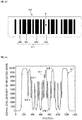
- This code scanner irradiates a laser beam or the like onto a code image 51 formed on an object 50 to be read as shown in FIG. 12 , receives reflected light thereof and performs any electrical transactions thereon to read information contained in the code image 51.
- the code image 51 is composed of bars (For example, wide bars WB in which their widths are wide and narrow bars NB in which their widths are narrow) and spaces (For example, wide spaces WS in which their widths are wide and narrow spaces NS in which their widths are narrow).
- bars For example, wide bars WB in which their widths are wide and narrow bars NB in which their widths are narrow
- spaces For example, wide spaces WS in which their widths are wide and narrow spaces NS in which their widths are narrow.
- the object 50 to be read is spotted with a stain N.
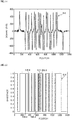
- FIG. 13 is a diagram showing a waveform example of a read signal D1 in which a vertical axis indicates a signal level (intensity of the reflected light) and a horizontal axis indicates position. As shown in FIG. 13 , the information contained in the code image 51 read by the code scanner is read as the read signal D1.
- This read signal D1 contains a wide bar waveform WB1 which has a downward large convex shape, a narrow bar waveform NB1 which has a downward small convex shape, a wide space waveform WS1 which has an upward large convex shape and a narrow space waveform NS1 which has an upward small convex shape, which respectively correspond to the wide bar WB, the narrow bar NB, the wide space WS and the narrow space NS in the code image 51. Accordingly, when the object 50 to be read is spotted with the stain N as shown in FIG. 12 , the read signal D1 contains any noise N1.
- FIG. 14 is a diagram showing a waveform example of a derivative signal D2 in which a vertical axis indicates a signal level and a horizontal axis indicates position.
- the code scanner differentiates the read signal D1 to produce the derivative signal D2.
- this derivative signal D2 has a waveform in which inflection points of the wide bar waveform WB1, the narrow bar waveform NB1, the wide space waveform WS1 and the narrow space waveform NS1 in the read signal D1 are their extreme values.
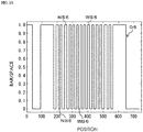
- FIG. 15 is a diagram showing a waveform example of a binarization signal D3 in which a vertical axis indicates bar/space (the bar in a case of "0" and the space in a case of "1") and a horizontal axis indicates position.
- the code scanner produces the binarization signal D3 by using the inflection points of the derivative signal D2 as standing points thereof or falling points thereof.
- this binarization signal D3 contains a wide bar signal WB3, a narrow bar signal NB3, a wide space signal WS3 and a narrow space signal NS3, which respectively correspond to the wide bar waveform WB1, the narrow bar waveform NB1, the wide space waveform WS1 and the narrow space waveform NS1. Further, the binarization signal D3 contains also a noise signal N3 which corresponds to the noise N1 in the read signal D1.
- the binarization signal D3 contains the noise signal N3 so that it is impossible to decode the information contained in the code image 51 correctly.
- FIG. 16 is a diagram showing a waveform example of a read signal D4 in which a vertical axis indicates a signal level (intensity of the reflected light) and a horizontal axis indicates position.
- This read signal D4 contains a wide bar waveform WB4 which has a downward large convex shape, a narrow bar waveform NB4 which has a downward small convex shape, a wide space waveform WS4 which has an upward large convex shape and a narrow space waveform NS4 which has an upward small convex shape, which respectively correspond to the wide bar WB, the narrow bar NB, the wide space WS and the narrow space NS in the code image 51, which is similar to the read signal D1 described on FIG. 13 .
- the read signal D4 contains no noise N1 like the read signal D1, because the code scanner and the object 50 to be read are away from each other by a distance more than the focal distance.
- FIG. 17 is a diagram showing a waveform example of a derivative signal D5 in which a vertical axis indicates a signal level and a horizontal axis indicates position.
- the code scanner differentiates the read signal D4 to produce the derivative signal D4.
- this derivative signal D5 has a waveform in which inflection points of the wide bar waveform WB4, the narrow bar waveform NB4, the wide space waveform WS4 and the narrow space waveform NS4 in the read signal D4 are their extreme values. All the width lengths between the inflection points become almost the same length.
- FIG. 18 is a diagram showing a waveform example of a binarization signal D6 in which a vertical axis indicates bar/space (the bar in a case of "0" and the space in a case of "1") and a horizontal axis indicates position.
- the code scanner produces the binarization signal D6 by using the inflection points of the derivative signal D5 as standing points thereof or falling points thereof.
- this binarization signal D6 contains a wide bar signal WB6, a narrow bar signal NB6, a wide space signal WS6 and a narrow space signal NS6, which respectively correspond to the wide bar waveform WB4, the narrow bar waveform NB4, the wide space waveform WS4 and the narrow space waveform NS4.
- the wide bar signal WB6, the narrow bar signal NB6, the wide space signal WS6 and the narrow space signal NS6 all have almost the same length as each other. This disables the information contained in the code image 51 from being correctly decoded.
- US 5612531 discloses a barcode reader having a derivative circuit and two thresholding circuits that include peak detectors.
- US 2005/274809 and EP 1150240 relate to derivative signals, whilst DE 10 2006 008727 discusses detecting peaks in autocorrelation values.
- a decoding method according to this invention is provided in claim 1.
- the photoelectric conversion is performed on the light reflected by an object to be read, a read signal indicating intensity of the reflected light is produced, and the produced read signal is differentiated to produce a derivative signal.
- the inflection points of intensity of the reflected light in the read signal are detected from the produced derivative signal and peak levels, each of which is an extreme value of the intensity of the reflected light, the peak level corresponding to a width length between the detected inflection points, are detected.
- a difference between the detected peak levels is then obtained and a threshold value for decoding the read signal is set from the obtained difference between the peak levels. This enables the read signal to be decoded based on the set threshold value.
- the decoding method and the decoding-processing apparatus it is possible to decode the read signal without using any complicated algorithm or fast CPU even when printing quality of the code image (object to be read) is inferior or even when the code image is read in its defocus state to produce the read signal. As a result thereof, it is possible to provide the decoding method and the decoding-processing apparatus by which a read performance is improved.
- This invention has an object to provide the decoding method and the decoding-processing apparatus by which the read signal of code image can be decoded without using any complicated algorithm or fast CPU or even when the object to be read is spotted with a stain or its printing quality is inferior or it can be decoded even when the read signal is read in its defocus state.
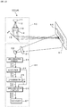
- the code scanner 100 is provided with an imaging lens 21, an image sensing device 22, a line extracting portion 23, an amplifier 24, a differentiator 25, a binarization circuit 26 and a decoder 27.
- the code scanner 100 makes light reflected by the code image 51 formed on the object 50 to be read incident on the imaging lens 21 to perform condensation of light and makes it image-form on the image sensing device 22 such as CCD and CMOS.
- the image sensing device 22 is one example of the read signal producing portion, performs photoelectric conversion on the reflected light according to the intensity of the reflected light, produces read signal D1, D4 which is analog electric signal and outputs the produced read signal D1, D4 to the line extracting portion 23.
- the image sensing device 22 is connected to the line extracting portion 23.
- the line extracting portion 23 extracts every one line from the read signal D1, D4 output from the image sensing device 22 to output it to the amplifier 24.
- the line extracting portion 23 is connected to the amplifier 24.
- the amplifier 24 amplifies signal levels of the read signal D1, D4 output from the line extracting portion 23 up to a desired level to output it to the differentiator 25 and the binarization circuit 26.
- the amplifier 24 is connected to the differentiator 25 and the binarization circuit 26.
- the differentiator 25 is one example of derivative signal producing portion, differentiates the read signal D1, D4 amplified by the amplifier 24 to produce derivative signal D2, D5 and outputs it to the binarization circuit 26.
- the differentiator 25 is connected to the binarization circuit 26.
- the binarization circuit 26 is one example of binarization portion and receives the read signal D1, D4 output from the amplifier 24 and the derivative signal D2, D5 output from the differentiator 25.
- the binarization circuit 26 detects inflection points of intensity of the reflected light in the read signal D1, D4 by detecting extreme values of the derivative signal D2, D5 from the received derivative signal D2, D5.
- the extreme values of the derivative signal D2, D5 correspond to positions in which there are the inflection points of intensity of the reflected light in the read signal D1, D4.
- the binarization circuit 26 binarizes the read signal D1, D4 output from the amplifier 24 on the basis of the detected inflection points to produce the binarization signals D3, D6 having information on width lengths between the inflection points.
- the binarization circuit 26 outputs the produced binarization signal D3, D6 to the decoder 27. Further, the binarization circuit 26 then detects peak levels, each of which is an extreme value of the intensity of the reflected light, the peak level corresponding to a width length between the inflection points, and outputs to the decoder 27 peak level information D7 which is information containing a value of the detected peak level (for example, a value (9800) of signal level of peak level C1 shown in FIG. 2 , which will be described later) and positions of the peak levels (for example, a position (350) of the peak level C1 shown in FIG. 2 ).
- a value of the detected peak level for example, a value (9800) of signal level of peak level C1 shown in FIG. 2 , which will be
- the binarization circuit 26 is connected to the decoder 27.
- the decoder 27 is one example of decoding portion, and extracts width length between the inflection points and values of the peak levels from the binarization signal D3, D6 output from the binarization circuit 26 and the peak level information D7.
- the decoder 27 aggregates the width length and the values of the peak levels thus extracted and sets normal value regions each relating to the width lengths and the peak levels based on the aggregation result.
- the decoder 27 then deletes the width lengths and the peak levels outside the set normal value regions as noises.
- the normal value region is a region such that, for example, if the aggregation result of the width lengths and the values of the peak levels are distributed according to a normal distribution, the width lengths and the values of the peak levels which are close to this distribution should be set to be normal and the width lengths and the values of the peak levels which are away from this distribution should be set to be abnormal.
- the decoder 27 obtains a difference between the peak levels and sets threshold values each for decoding the read signal D1, D4 from the obtained differences between the peak levels. For example, the decoder 27 determines whether or not the difference between the peal levels is smaller than a predetermined value, and when the determined result is smaller than the predetermined value, it sets the threshold values from the width lengths or when the determined result is not smaller than the predetermined value, it sets the threshold values from the peak levels. It is to be noted that the decoder 27 may obtain frequency distribution of the detected peak levels to set the threshold values for decoding the read signal D1, D4 based on the obtained frequency distribution.
- the decoder 27 decodes the read signal D1, D4 based on the threshold values, plots of the width lengths and peak levels inside the normal value region (plots shown in FIG. 5 , which will be described later) and the positions of the peak levels in the peal level information D7 so that information contained in the code image 51 can be decoded.
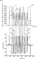
- a waveform shown in a top part of FIG. 2 shows a processing example of the read signal D1 by the binarization circuit 26 in which a vertical axis indicates a signal level (intensity of the reflected light) and a horizontal axis indicates position.
- a waveform shown in a bottom part of FIG. 2 shows a processing example of the derivative signal D2 by the binarization circuit 26 in which a vertical axis indicates the signal level and a horizontal axis indicates the position.
- the code image 51 shown in FIG. 12 is read; the read signal D1 shown in FIG. 13 is produced by the image sensing device 22, the line extracting portion 23 and the amplifier 24; and the derivative signal D2 shown in FIG. 14 is produced by the differentiator 25 based on this read signal D1.
- the waveform shown in the top part of FIG. 2 is identical with the read signal D1 shown in FIG. 13 and the waveform shown in the bottom part of FIG. 2 is identical with the derivative signal D2 shown in FIG. 14 .
- the binarization circuit 26 detects the inflection points A1, A2, which correspond to the extreme values of the derivative signal D2, of the intensity of the reflected light in the read signal D1 (In other words, the extreme values of the derivative signal D2 correspond to the inflection points of the read signal D1).
- the binarization circuit 26 detects peak level C1 which corresponds to width length B1 between the inflection points based on the detected inflection points A1, A2, and is the extreme value of the intensity of the reflected light.
- width lengths B2, B3, B4 respectively correspond to the peak levels C2, C3, C4.
- the peak levels C1, C2, C3, C4 respectively correspond to the wide space WS, the narrow space NS, the wide bar WB and the narrow bar NB, which are shown in FIG. 12 .
- the stain N shown in FIG. 12 appears as the peak levels C5, C6.
- the width lengths B1, B2, B3, B4 are fixed so as to correspond to the widths of bar and space in the code image 51.
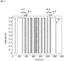
- FIG. 3 is a diagram showing a processing example of the binarization signal D3 by the binarization circuit 26 in which a vertical axis indicates bar/space (the bar in a case of "0" and the space in a case of "1") and a horizontal axis indicates position.
- the binarization circuit 26 produces the binarization signal D3 by using the detected inflection points A1, A2 of the derivative signal D2 in the waveform shown in the bottom part of FIG. 2 as standing points thereof or falling points thereof.
- the width lengths B1, B2, B3, B4 are fixed on the basis of this binarization signal D3.
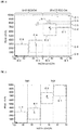
- FIG. 4 is a diagram showing a frequency distribution example in which peak levels and width lengths produced by by the binarization circuit 26 are plotted when a vertical axis indicates peak level and a horizontal axis indicates width length.
- positive numbers are fixed as a space region in which the wide space WS and the narrow space NS exist while negative numbers are fixed as a bar region in which the wide bar WB and the narrow bar NB exist.
- the decoder 27 aggregates the peak levels C1 through C4 shown in the waveform shown in the top part of FIG. 2 and the width lengths B1 through B4 produced in FIG. 3 to set normal value regions E1 through E4, which are shown by alternate long and short dash lines, relating to the peak levels C1 through C4 and the width lengths B1 through B4 based on the aggregation result thereof.
- the normal value region E1 is a region relating to the wide space WS and is set by aggregating the width length B1 and the peak level C1 and assuming that for example, the aggregation result is distributed according to a normal distribution.
- the normal value region E2 is a region relating to the narrow space NS and is set by aggregating the width length B2 and the peak level C2 and assuming that for example, the aggregation result is distributed according to a normal distribution.
- the normal value region E3 is a region relating to the wide bar WB and is set by aggregating the width length B3 and the peak level C3 and assuming that for example, the aggregation result is distributed according to a normal distribution.
- the normal value region E4 is a region relating to the narrow bar NB and is set by aggregating the width length B4 and the peak level C4 and assuming that for example, the aggregation result is distributed according to a normal distribution.
- the decoder 27 deletes the width length(s) and the peak level(s) as noise. Namely, since, in FIG. 4 , the peak levels C5, C6 exist outside the set normal value regions E1 through E4, the decoder 27 deletes the noise N1 corresponding to the peak levels C5, C6 (or does not decode the noise N1).
- FIG. 5 is a diagram showing a processing example in which the noise N is deleted from the frequency distribution example shown in FIG. 4 and threshold values ThB1, ThS1 are set.
- the threshold value ThB1 is a boundary value between the wide bar WB and the narrow bar NB and if value of the width length is smaller than the threshold value ThB1, the bar corresponding to the plot thereof is determined as the wide bar WB while if value of the width length is larger than the threshold value ThB1, the bar corresponding to the plot thereof is determined as the narrow bar NB.
- the threshold value ThS1 is a boundary value between the wide space WS and the narrow space NS and if value of the width length is smaller than the threshold value ThS1, the space corresponding to the plot thereof is determined as the narrow space NS while if value of the width length is larger than the threshold value ThS1, the space corresponding to the plot thereof is determined as the wide space WS.
- the decoder 27 sets the threshold value ThB1 in relation to the width length between the normal value region E3 and the normal value region E4.
- the decoder 27 also sets the threshold value ThS1 in relation to the width length between the normal value region E1 and the normal value region E2. Namely, in FIG. 5 , the decoder 27 sets the threshold values ThB1, ThS1 based on the width lengths.
- the threshold values ThB1, ThS1 may be set based on the difference between the respective width lengths B1 through B4 (for example, the threshold value ThS1 may be obtained from (B1+B2)/2 and the threshold value ThB1 may be obtained from (B3+B4)/2).
- the decoder 27 decodes the read signal D1 using the threshold values ThB1, ThS1 set on the basis of the frequency distribution shown in FIG. 5 (or the difference between the width lengths B1 through B4).
- the code scanner 100 even when the object 50 to be read is spotted with the stain N or printing quality thereof is inferior, it is possible to decode the read signal D1 of the code image 51 surely because the threshold values ThB1, ThS1 for decoding the read signal D1 are set.
- the defocus state is referred to as an out-of-focus state where a light-receiving surface of the code scanner deviates from an image forming surface of a lens to an optical axis direction.
- a waveform shown in a top part of FIG. 6 shows a processing example of the read signal D4 by the binarization circuit 26 in which a vertical axis indicates a signal level (intensity of the reflected light) and a horizontal axis indicates position.
- a waveform shown in a bottom part of FIG. 6 shows a processing example of the derivative signal D5 by the binarization circuit 26 in which a vertical axis indicates the signal level and a horizontal axis indicates the position.
- the code image 51 shown in FIG. 12 is read in its defocus state; the read signal D4 shown in FIG. 16 is produced by the image sensing device 22, the line extracting portion 23 and the amplifier 24; and the derivative signal D5 shown in FIG. 17 is produced by the differentiator 25 based on this read signal D4.
- the waveform shown in the top part of FIG. 6 is identical with the read signal D4 shown in FIG. 16 and the waveform shown in the bottom part of FIG. 6 is identical with the derivative signal D5 shown in FIG. 17 .
- the binarization circuit 26 detects the inflection points F1, F2, which correspond to the extreme values of the derivative signal D5, of the intensity of the reflected light in the read signal D4 (In other words, the extreme values of the derivative signal D5 correspond to the inflection points of the read signal D4).
- the binarization circuit 26 detects peak level H1 which corresponds to width length G1 between the inflection points based on the detected inflection points F1, F2, and is the extreme value of the intensity of the reflected light.
- width lengths G2, G3, G4 respectively correspond to the peak levels H2, H3, H4.
- the peak levels H1, H2, H3, H4 respectively correspond to the wide space WS, the narrow space NS, the wide bar WB and the narrow bar NB, which are shown in FIG. 11 .
- the peak levels C5, C6 which have been shown in the waveform of the top part of FIG. 2 and are depended on the strain shown in FIG. 12 do not appear because the code image 51 is read in its defocus state.
- the width lengths G1, G2, G3, G4, however, are almost the same length as each other because the code image 51 is read in its defocus state.
- FIG. 7 is a diagram showing a processing example of the binarization signal D6 by the binarization circuit 26 in which a vertical axis indicates bar/space (the bar in a case of "0" and the space in a case of "1") and a horizontal axis indicates position.
- the binarization circuit 26 produces the binarization signal D6 by using the detected inflection points F1, F2 of the derivative signal D5 in the waveform shown in the bottom part of FIG. 6 as standing points thereof or falling points thereof.
- the width lengths G1 through G4 are fixed on the basis of this binarization signal D6.
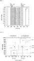
- FIG. 8 is a diagram showing a frequency distribution example in which peak levels and width lengths produced by by the binarization circuit 26 are plotted when a vertical axis indicates peak level and a horizontal axis indicates width length.
- positive numbers are fixed as a space region in which the wide space WS and the narrow space NS exist while negative numbers are fixed as a bar region in which the wide bar WB and the narrow bar NB exist.
- the decoder 27 aggregates the peak levels H1 through H4 shown in the waveform shown in the top part of FIG. 6 and the width lengths G1 through G4 produced in FIG. 7 to set normal value regions I1 through 14, which are shown by alternate long and short dash lines, relating to the peak levels H1 through H4 and the width lengths G1 through G4 based on the aggregation result thereof.
- the normal value region I1 is a region relating to the wide space WS and is set by aggregating the width length G1 and the peak level H1 and assuming that for example, the aggregation result is distributed according to a normal distribution.
- the normal value region 12 is a region relating to the narrow space NS and is set by aggregating the width length G2 and the peak level H2 and assuming that for example, the aggregation result is distributed according to a normal distribution.
- the normal value region 13 is a region relating to the wide bar WB and is set by aggregating the width length G3 and the peak level H3 and assuming that for example, the aggregation result is distributed according to a normal distribution.
- the normal value region 14 is a region relating to the narrow bar NB and is set by aggregating the width length G4 and the peak level H4 and assuming that for example, the aggregation result is distributed according to a normal distribution.
- the decoder 27 deletes the width length(s) and the peak level(s) as noise. In this example, however, since any noise based on the stain N does not read from the code image 51, such processing is not carried out.
- FIG. 9 is a diagram showing a processing example in which threshold values ThB2, ThS2 are set from the frequency distribution example shown in FIG. 8 .
- threshold values ThB2, ThS2 are set from the frequency distribution example shown in FIG. 8 .
- FIG. 9 there is any correlation between a value of the peak level and a width length of the bar or space.
- the smaller the value of the peak level is, the width length of the bar or space becomes smaller (corresponding to the narrow bar NB or the narrow space NS).
- the threshold value ThB2 is a boundary value between the wide bar WB and the narrow bar NB and if value of the peak level is smaller than the threshold value ThB2, the bar corresponding to the plot thereof is determined as the narrow bar NB while if value of the peak level is larger than the threshold value ThB2, the bar corresponding to the plot thereof is determined as the wide bar WB.
- the threshold value ThS2 is a boundary value between the wide space WS and the narrow space NS and if value of the peak level is smaller than the threshold value ThS2, the space corresponding to the plot thereof is determined as the narrow space NS while if value of the peak level is larger than the threshold value ThS2, the space corresponding to the plot thereof is determined as the wide space WS.
- the decoder 27 sets the threshold value ThS2 in relation to the peak level between the normal value region I1 and the normal value region 12 which are shown in FIG.9 .
- the decoder 27 also sets the threshold value ThB2 in relation to the peak level between the normal value region 13 and the normal value region 14. Namely, in FIG. 9 , the decoder 27 sets the threshold values ThB2, ThS2 based on the peak levels, not the width lengths as shown in FIG. 5 . This is because when setting the threshold values based on the width lengths as shown in FIG. 5 , the normal value region I1 and the normal value region 12 or the normal value region 13 and the normal value region 14 are overlapped in regard to the width length (as shown in FIG. 7 , all of the width lengths are almost the same length as each other) so that the threshold values cannot be set.
- the threshold values ThB2, ThS2 may be set based on the difference between the respective peak levels H1 through H4 (for example, the threshold value ThS2 may be obtained from (H1+H2)/2 and the threshold value ThB2 may be obtained from (H3+H4)/2).
- the decoder 27 decodes the read signal D4 using the threshold values ThB2, ThS2 set on the basis of the frequency distribution shown in FIG. 9 (or the difference between the peak levels H1 through H4).
- the code scanner 100 receives light reflected by the code image 51 which is formed on the object 50 to be read.
- the code scanner 100 makes the imaging lens 21 perform condensation of the reflected light and makes it image-form on the image sensing device 22 to capture the code image 51 in the code scanner 100.
- photoelectric conversion is performed by the image sensing device 22 so that the read signal D1, D4 are produced.
- the read signal D1, D4 is extracted every one line by the line extracting portion 23 and signal level of the read signal D1, D4 is amplified to a predetermined level by the amplifier 24 (see FIGS. 13 and 16 ).
- the operation goes to a step ST2 in which the differentiator 25 differentiates the read signal D1, D4 to produce the derivative signal D2, D5 (see FIGS. 14 and 17 ).
- the operation goes to a step ST3 in which the binarization circuit 26 detects the extreme values of the derivative signal D2, D5 as the inflection points A1, A2, F1, F2 of the signal level in the read signal D1 (see FIGS. 2 and 6 ).
- the binarization circuit 26 then binarizes the read signal D1, D4 output from the amplifier 24 on the basis of the detected inflection points A1, A2, F1, F2 to produce the binarization signal D3, D6 (see FIGS. 3 and 7 ).
- the operation goes to a step ST4 in which the binarization circuit 26 detects the width lengths B1 through B4, G1 through G4 between the inflection points from the produced binarization signal D3, D6 and detects the peak levels C1 through C4, H1 through H4, which correspond to the width lengths B1 through B4, G1 through G4 (see FIGS. 2 and 6 ).
- the binarization circuit 26 then produces the peak level information D7 which is information containing values of the detected peak levels C1 through C4, H1 through H4 and positions of the peak levels.
- the operation goes to a step ST5 in which the decoder 27 extracts the width lengths B1 through B4, G1 through G4 and values of the peak levels C1 through C4, H1 through H4 from the binarization signal D3, D6 produced in the binarization circuit 26 and the peak level information D7.
- the decoder 27 then aggregates the width lengths B1 through B4, G1 through G4 and the peak levels C1 through C4, H1 through H4 thus extracted and sets normal value regions E1 through E4, I1 through 14 relating to the width lengths B1 through B4, G1 through G4 and the peak levels C1 through C4, H1 through H4 (see FIGS. 4 and 7 ) based on the aggregation result thereof.
- the operation goes to a step ST6 in which the decoder 27 determines whether or not the width lengths B1 through B4, G1 through G4 and the peak levels C1 through C4, H1 through H4 exist within the set normal value regions E1 through E4, I1 through 14. If the width lengths B1 through B4, G1 through G4 and the peak levels C1 through C4, H1 through H4 exist within the set normal value regions E1 through E4, I1 through 14, the operation goes to a step ST8 and if not, the operation goes to a step ST8.
- the decoder 27 deletes the width lengths and the peak levels outside the normal value regions E1 through E4, I1 through 14 as noise.
- the peak levels C5, C6 shown in FIG. 3 are noise N1.
- the decoder 27 determines whether or not the difference between the peal levels C1 through C4, H1 through H4 is smaller than a predetermined value which has been previously stored. If the difference between the peal levels C1 through C4, H1 through H4 is smaller than the predetermined value, the operation goes to a step ST9 and if the difference between the peal levels C1 through C4, H1 through H4 is not smaller than the predetermined value, the operation goes to a step ST10.
- the operation goes to the step ST9.
- the difference between the peak level H1 and the peak level H2 is large and the difference between the peak level H3 and the peak level H4 is also large. In this case, the operation goes to the step ST10.
- the decoder 27 sets threshold values based on the width lengths B1 through B4, G1 through G4. For example, in FIG. 5 , the decoder 27 sets the threshold value ThS1 between the normal value region E1 containing the width length B1 and the normal value region E2 containing the width length B2 and sets the threshold value ThB1 between the normal value region E3 containing the width length B3 and the normal value region E4 containing the width length B4. If the threshold values ThB1, THS1 are set, then the operation goes to a step ST11.
- the decoder 27 sets threshold values based on the peal levels C1 through C4, H1 through H4. For example, in FIG. 9 , the decoder 27 sets the threshold value ThS2 between the normal value region I1 containing the peak level H1 and the normal value region 12 containing the peak level H2 and sets the threshold value ThB2 between the normal value region 13 containing the peak level H3 and the normal value region 14 containing the peak level H4. If the threshold values ThB2, THS2 are set, then the operation goes to the step ST11.
- the decoder 27 decodes information on the code image 51 (the read signal D1, D4) based on the set threshold values ThB1, ThS1, ThB2, ThS2, plots of the width lengths and peak levels inside the normal value regions and the positions of the peak levels in the peal level information D7.
- the photoelectric conversion is performed on the light reflected by the code image 51, the read signal D1, D4 indicating intensity of the reflected light is produced, and the produced read signal D1, D4 is differentiated to produce the derivative signal D2, D5.
- the inflection points A1, A2, F1, F2 of intensity of the reflected light in the read signal D1, D2 are detected from the produced derivative signal D2, D5 and the peak levels C1 through C4, H1 through H4, each of which is an extreme value of the intensity of the reflected light, the peak levels corresponding to the width lengths B1 through B4, G1 through G4 between the detected inflection points, are detected.
- the difference between the detected peak levels C1 through C4, H1 through H4 is then obtained and the threshold values ThB1, ThS1, ThB2, ThS2 for decoding the read signal D1, D4 are set from the obtained difference between the peak levels C1 through C4, H1 through H4.
- the decoding method according to this invention may be available even for a two-dimensional code.
- an image of one frame of the two-dimensional code is shot by the code scanner shown in FIG. 1 and the shot image of the two-dimensional code is scanned every line on a horizontal direction and a vertical direction so that the processing shown in FIG. 10 is carried out.
- By adding up the data binarized every line again on an image of one frame it is possible to perform the decoding.
- the decoding method described in this embodiment is also available for not only the code scanner but also an apparatus for decoding the data such as optical disc play-back equipment.
- This invention is also available to four value code.
- the threshold values are set from the peak levels for first value since the extent of defocus thereof is strong while the threshold values are set from the width lengths for second, third and fourth values since the extent of defocus thereof is weak.
- the code scanner 100A is composed of the photoirradiation portion 10 and a signal-processing portion 20.
- the photoirradiation portion 10 is provided with a laser beam source 11, a condensing lens 13, an aperture stop 14 and a scanning mirror 15.
- the photoirradiation portion 10 condenses the laser beam emitted from a light-emitting point 12 of the laser beam source 11 such as a semiconductor laser by the condensing lens 13 and then reduces its diameter by the aperture stop 14. It deflects the beam toward the object 50 to be read by the scanning mirror 15 and irradiates the beam on the code image 51 formed on the object 50 to be read.
- a light-emitting point 12 of the laser beam source 11 such as a semiconductor laser
- the photoirradiation portion 10 then scans on the code image 51 by beam spots of the laser beam.
- the scanning mirror 15 is shown as a plane mirror in FIG. 11 , a polygon mirror which is a regular polygon prism with mirror sides may be used therefor.
- the signal-processing portion 20 is provided with the imaging lens 21, the image sensing device 22, the line extracting portion 23, the amplifier 24, the differentiator 25, the binarization circuit 26 and the decoder 27.
- the signal-processing portion 20 makes the scanned laser beam reflected by the code image 51 formed on the object 50 to be read incident on the imaging lens 21 to perform condensation of light and makes it image-form on the image sensing device 22 such as CCD and CMOS.
- the line extracting portion 23, the amplifier 24, the differentiator 25, the binarization circuit 26 and the decoder 27 are identical to them of the above-mentioned first embodiment, the description of which will be omitted.
- the code scanner 100A is provided with the photoirradiation portion 10 irradiating the laser beam toward the object 50 to be read whereby it is possible to decode the read signal even when the read signal D1, D4 is based on the code image 51 which is spotted with a stain N or printing quality of which is inferior or even when the read signals D1, D4 are read in its defocus state.
- This invention is excellent in that it is possible to decode the signal without using any complicated algorithm or fast CPU even when the object 50 to be read is spotted with a stain or the like or any printing quality thereof is inferior or even when the read signals are read in its defocus state by a new method in which a conventional algorithm is used while the threshold setting alters from the width lengths to the peak levels, which could not be easily to be invented by a person who has an ordinary skill in the art.
Landscapes
- Engineering & Computer Science (AREA)
- Physics & Mathematics (AREA)
- General Physics & Mathematics (AREA)
- Electromagnetism (AREA)
- Theoretical Computer Science (AREA)
- Artificial Intelligence (AREA)
- Toxicology (AREA)
- General Health & Medical Sciences (AREA)
- Computer Vision & Pattern Recognition (AREA)
- Health & Medical Sciences (AREA)
- Quality & Reliability (AREA)
- Data Mining & Analysis (AREA)
- Mathematical Physics (AREA)
- Mathematical Analysis (AREA)
- General Engineering & Computer Science (AREA)
- Software Systems (AREA)
- Databases & Information Systems (AREA)
- Pure & Applied Mathematics (AREA)
- Mathematical Optimization (AREA)
- Computational Mathematics (AREA)
- Algebra (AREA)
- Image Input (AREA)
- Facsimile Image Signal Circuits (AREA)
- Optical Recording Or Reproduction (AREA)
- Character Input (AREA)
Claims (5)
- Procédé de décodage comprenant :une première étape consistant à effectuer une conversion photoélectrique sur la lumière réfléchie par un objet (50, 51) à lire et produire un signal de lecture indiquant l'intensité de la lumière réfléchie ;une deuxième étape consistant à différencier le signal de lecture produit dans la première étape pour produire un signal dérivé ;une troisième étape consistant à détecter des points d'inflexion d'intensité de la lumière réfléchie dans le signal de lecture à partir du signal dérivé produit dans la deuxième étape et détecter dans le signal de lecture des niveaux maximaux ou minimaux, chacun d'eux étant une valeur extrême de l'intensité de la lumière réfléchie entre points d'inflexion détectés, chaque niveau maximal ou minimal correspondant à une largeur entre les points d'inflexion détectés ;et caractérisé parune quatrième étape consistant à agréger respectivement des largeurs entre les points d'inflexion et les niveaux maximaux et minimaux, et régler des régions de valeur normale relativement à la largeur et aux niveaux maximaux et minimaux sur la base des résultats d'agrégation ;une cinquième étape consistant à régler une première valeur seuil entre les niveaux maximaux agrégés détectés dans la quatrième étape pour décoder le signal de lecture à partir des niveaux maximaux, et régler une deuxième valeur seuil entre les niveaux minimaux agrégés détectés dans la quatrième étape pour détecter le signal de lecture à partir des niveaux minimaux ; etune sixième étape consistant à décoder le signal de lecture sur la base des première et deuxième valeurs seuils réglées dans la cinquième étape.
- Procédé de décodage selon la revendication 1 dans lequel une longueur de largeur et un niveau maximal ou minimal à l'extérieur de la région de valeur normale réglée sont supprimés en tant que bruit.
- Procédé de décodage selon la revendication 1 dans lequel, dans la troisième étape, une distribution de fréquence des niveaux maximaux ou minimaux détectés dans la deuxième étape est obtenue, et les première et deuxième valeurs seuils pour décoder le signal de lecture sont réglées sur la base de la distribution de fréquence obtenue.
- Procédé de décodage selon la revendication 1 dans lequel, dans la troisième étape, il est déterminé si la différence entre les niveaux maximaux ou les niveaux minimaux est plus grande qu'une valeur prédéterminée ou non, et quand le résultat déterminé est plus grand que la valeur prédéterminée, les première et deuxième valeurs seuils sont réglées à partir des largeurs, ou quand le résultat déterminé n'est pas plus grand que la valeur prédéterminée, les première et deuxième valeurs seuils sont réglées à partir des niveaux maximaux et minimaux.
- Appareil de décodage-traitement (100) comprenant :une partie produisant un signal de lecture (21, 22, 23, 24) utilisable pour effectuer une conversion photoélectrique sur de la lumière réfléchie par un objet (50, 51) à lire et produire un signal de lecture indiquant l'intensité de la lumière réfléchie ;une partie produisant un signal dérivé (25) utilisable pour différencier le signal de lecture produit dans la partie produisant un signal de lecture pour produire un signal dérivé ;une partie de binarisation (26) utilisable pour détecter des points d'inflexion d'intensité de la lumière réfléchie dans le signal de lecture à partir du signal dérivé et pour détecter dans le signal de lecture des niveaux maximaux ou minimaux, chacun d'eux étant une valeur extrême de l'intensité de la lumière réfléchie entre points d'inflexion détectés, chaque niveau maximal ou minimal correspondant à une largeur entre les points d'inflexion détectés ;et caractérisé parune partie d'agrégation (27) utilisable pour agréger respectivement des largeurs entre les points d'inflexion et les niveaux maximaux et minimaux ;une partie de réglage (27) utilisable pour régler des régions de valeur normale relativement à la largeur et aux niveaux maximaux et minimaux sur la base des résultats d'agrégation ; etune partie de décodage (27) utilisable pour régler une première valeur seuil entre les niveaux maximaux agrégés générés par la partie d'agrégation pour décoder le signal de lecture à partir des niveaux maximaux, et utilisable pour régler une deuxième valeur seuil entre les niveaux minimaux agrégés générés par la partie d'agrégation pour décoder le signal de lecture à partir des niveaux minimaux, et utilisable pour décoder le signal de lecture sur la base des première et deuxième valeurs seuils réglées.
Applications Claiming Priority (2)
| Application Number | Priority Date | Filing Date | Title |
|---|---|---|---|
| JP2010150227A JP5398653B2 (ja) | 2010-06-30 | 2010-06-30 | デコード方法及びデコード処理装置 |
| PCT/JP2011/064711 WO2012002335A1 (fr) | 2010-06-30 | 2011-06-27 | Procédé de décodage, et dispositif de traitement de décodage |
Publications (3)
| Publication Number | Publication Date |
|---|---|
| EP2590108A1 EP2590108A1 (fr) | 2013-05-08 |
| EP2590108A4 EP2590108A4 (fr) | 2014-01-01 |
| EP2590108B1 true EP2590108B1 (fr) | 2017-01-11 |
Family
ID=45402043
Family Applications (1)
| Application Number | Title | Priority Date | Filing Date |
|---|---|---|---|
| EP11800799.6A Not-in-force EP2590108B1 (fr) | 2010-06-30 | 2011-06-27 | Procédé de décodage, et dispositif de traitement de décodage |
Country Status (5)
| Country | Link |
|---|---|
| US (1) | US9262665B2 (fr) |
| EP (1) | EP2590108B1 (fr) |
| JP (1) | JP5398653B2 (fr) |
| CN (1) | CN102971743B (fr) |
| WO (1) | WO2012002335A1 (fr) |
Families Citing this family (4)
| Publication number | Priority date | Publication date | Assignee | Title |
|---|---|---|---|---|
| CN103745185B (zh) * | 2013-12-27 | 2017-01-18 | 沈阳东软医疗系统有限公司 | 一种识别探测器晶体单元位置的方法和装置 |
| JP6539050B2 (ja) * | 2014-09-04 | 2019-07-03 | 株式会社小糸製作所 | 車両用灯具およびその光源の異常検出器 |
| CN105628195A (zh) * | 2014-10-31 | 2016-06-01 | 富泰华工业(深圳)有限公司 | 光源亮度检测系统及方法 |
| CN104867141B (zh) * | 2015-05-14 | 2018-11-09 | 浙江工业大学 | 一种连续生产中的无纺布袋自动定位方法 |
Family Cites Families (46)
| Publication number | Priority date | Publication date | Assignee | Title |
|---|---|---|---|---|
| US4000397A (en) * | 1975-03-21 | 1976-12-28 | Spectra-Physics, Inc. | Signal processor method and apparatus |
| JPS53128230A (en) * | 1977-04-14 | 1978-11-09 | Shinko Electric Co Ltd | Method of reading bar code information in label reader |
| JPS5580181A (en) | 1978-12-13 | 1980-06-17 | Shinko Electric Co Ltd | Waveform shaping system in label reader |
| US4740675A (en) * | 1986-04-10 | 1988-04-26 | Hewlett-Packard Company | Digital bar code slot reader with threshold comparison of the differentiated bar code signal |
| US4798943A (en) * | 1986-09-30 | 1989-01-17 | Spectra-Physics, Inc. | Method and system for control of a bar code scanner threshold |
| US4716438A (en) * | 1986-11-17 | 1987-12-29 | Xerox Corporation | High speed electronic reprographic/printing machine |
| US5059773A (en) * | 1988-11-16 | 1991-10-22 | The Japan Steel Works, Ltd. | Bar code reader signal processing method and device |
| US5446272A (en) * | 1989-06-16 | 1995-08-29 | Symbol Technologies, Inc. | System for digitizing a scanned signal indicating changes in signal intensity |
| US5612531A (en) * | 1993-03-08 | 1997-03-18 | Symbol Technologies, Inc. | Bar code reader with multiple sensitivity modes using variable thresholding comparisons |
| US5272323A (en) * | 1989-11-22 | 1993-12-21 | Symbol Technologies, Inc. | Digitizer for barcode scanner |
| US5103080A (en) * | 1990-12-10 | 1992-04-07 | Symbol Technologies, Inc. | Digitizer signal processing circuit for a bar code |
| CA2053460A1 (fr) * | 1991-09-13 | 1993-03-14 | Eugene Bernard Joseph | Decodeur de formes d'onde analogiques |
| KR100257128B1 (ko) * | 1991-11-11 | 2000-05-15 | 시모야마 도시로 | 심볼정보판독장치 |
| DE4323293C2 (de) * | 1993-07-12 | 1996-07-25 | Sick Optik Elektronik Erwin | Verfahren und Abtastanordnung zur Identifizierung eines aus aufeinanderfolgenden hellen und dunklen Feldern bestehenden Codes |
| JPH09128523A (ja) | 1995-10-27 | 1997-05-16 | Ricoh Co Ltd | 画像読み取り装置 |
| JP3532014B2 (ja) * | 1995-11-30 | 2004-05-31 | 松下電器産業株式会社 | しきい値算出方法 |
| US6422467B2 (en) * | 1995-12-18 | 2002-07-23 | Metrologic Instruments, Inc. | Reading system a variable pass-band |
| US5734939A (en) * | 1996-01-26 | 1998-03-31 | Nikon Corporation | Camera capable of displaying information relating to the number of frames of film |
| US6012639A (en) * | 1996-11-01 | 2000-01-11 | Psc Scanning Inc. | Edge detection method and apparatus for shot noise limited signals |
| US5864129A (en) * | 1997-05-05 | 1999-01-26 | Psc Inc. | Bar code digitizer including a voltage comparator |
| US6000616A (en) * | 1997-05-12 | 1999-12-14 | Webscan, Inc. | Methods to determine and selectively sample positive and negative peak values occurring within a scan reflectance profile signal |
| JPH11272791A (ja) * | 1998-03-23 | 1999-10-08 | Toshiba Corp | パターン読み出し方法およびパターン読み出し装置 |
| US6168081B1 (en) | 1998-03-23 | 2001-01-02 | Kabushiki Kaisha Toshiba | Method and apparatus for reading invisible symbol |
| JP4085532B2 (ja) * | 1999-08-23 | 2008-05-14 | 株式会社デンソー | バーコード読取装置 |
| JP2001209751A (ja) | 2000-01-28 | 2001-08-03 | Olympus Optical Co Ltd | 適応二値化方式 |
| US6382511B1 (en) * | 2000-04-26 | 2002-05-07 | Ncr Corporation | Methods and apparatus for digitizing and processing of analog barcode signals |
| KR100715754B1 (ko) * | 2001-01-26 | 2007-05-08 | 후지쯔 가부시끼가이샤 | 정보 판독 방법 및 장치 |
| US6935564B2 (en) * | 2001-07-30 | 2005-08-30 | Bayer Healthcare Llc | Circuit and method for correcting influence of AC coupling |
| JP4202101B2 (ja) * | 2002-10-10 | 2008-12-24 | 富士通株式会社 | バーコード認識方法、および認識用デコード処理装置 |
| JP4257131B2 (ja) * | 2003-02-21 | 2009-04-22 | 富士通株式会社 | バーコード読取装置およびバーコード読取方法 |
| JP4257132B2 (ja) * | 2003-02-21 | 2009-04-22 | 富士通株式会社 | バーコード読取装置およびバーコード読取方法 |
| JP4070631B2 (ja) * | 2003-02-21 | 2008-04-02 | 富士通株式会社 | バーコード読取装置およびバーコード読取方法 |
| US7204422B2 (en) * | 2004-06-10 | 2007-04-17 | Psc Scanning, Inc. | System, circuit, and method for edge detection in a binary optical code |
| JP2006065909A (ja) | 2004-08-24 | 2006-03-09 | Funai Electric Co Ltd | 光ディスク再生装置 |
| JP4470848B2 (ja) | 2005-09-15 | 2010-06-02 | パナソニック電工株式会社 | 顔部品抽出方法及び顔認証装置 |
| DE102006008728B3 (de) * | 2006-02-24 | 2007-07-19 | Airbus Deutschland Gmbh | Verfahren zur Herstellung eines räumlichen Stabwerks als Kernstruktur einer Sandwichkonstruktion |
| DE102006008727A1 (de) * | 2006-02-24 | 2007-08-30 | Siemens Ag | Verfahren und Vorrichtung zum Erkennen eines Strichcodes |
| JP2008282262A (ja) * | 2007-05-11 | 2008-11-20 | Olympus Corp | バーコード読取装置およびバーコード読取方法 |
| JP2009110413A (ja) * | 2007-10-31 | 2009-05-21 | Olympus Corp | バーコード読取装置 |
| JP2009259059A (ja) * | 2008-04-18 | 2009-11-05 | Keyence Corp | バーコード読取装置及びバーコード読取方法 |
| JPWO2011034107A1 (ja) * | 2009-09-17 | 2013-02-14 | 株式会社オプトエレクトロニクス | 光学的情報読取装置およびその制御方法 |
| US9170192B2 (en) * | 2009-10-09 | 2015-10-27 | Lawrence D. Ziegler | Systems and methods for identifying materials utilizing multivariate analysis techniques |
| JP5515012B2 (ja) * | 2010-03-13 | 2014-06-11 | 日本電産サンキョー株式会社 | バーコード情報読取方法及びバーコード情報読取装置 |
| US8393541B2 (en) * | 2010-06-07 | 2013-03-12 | Key Control Holding, Inc. | Custom scanning device and automated car auction facility management |
| US8333326B2 (en) * | 2010-10-07 | 2012-12-18 | Nidec Sankyo Corporation | Stacked barcode reader and stacked barcode reading method |
| US8950678B2 (en) * | 2010-11-17 | 2015-02-10 | Hand Held Products, Inc. | Barcode reader with edge detection enhancement |
-
2010
- 2010-06-30 JP JP2010150227A patent/JP5398653B2/ja not_active Expired - Fee Related
-
2011
- 2011-06-27 US US13/807,667 patent/US9262665B2/en active Active
- 2011-06-27 CN CN201180033081.XA patent/CN102971743B/zh not_active Expired - Fee Related
- 2011-06-27 WO PCT/JP2011/064711 patent/WO2012002335A1/fr not_active Ceased
- 2011-06-27 EP EP11800799.6A patent/EP2590108B1/fr not_active Not-in-force
Non-Patent Citations (1)
| Title |
|---|
| None * |
Also Published As
| Publication number | Publication date |
|---|---|
| US9262665B2 (en) | 2016-02-16 |
| WO2012002335A1 (fr) | 2012-01-05 |
| US20130221103A1 (en) | 2013-08-29 |
| EP2590108A1 (fr) | 2013-05-08 |
| CN102971743A (zh) | 2013-03-13 |
| CN102971743B (zh) | 2015-11-25 |
| JP5398653B2 (ja) | 2014-01-29 |
| JP2012014425A (ja) | 2012-01-19 |
| EP2590108A4 (fr) | 2014-01-01 |
Similar Documents
| Publication | Publication Date | Title |
|---|---|---|
| CN102622569B (zh) | 具有边缘检测增强的条码读取器 | |
| US20020044689A1 (en) | Apparatus and method for global and local feature extraction from digital images | |
| US7949187B2 (en) | Character string recognition method and device | |
| US9251430B2 (en) | Apparatus, method, and program for character recognition using minimum intensity curve of image data | |
| US8718370B2 (en) | Optical information-reading apparatus and optical information-reading method | |
| EP2590108B1 (fr) | Procédé de décodage, et dispositif de traitement de décodage | |
| US7333656B2 (en) | Image processing method and image processing apparatus | |
| EP1114391A4 (fr) | Systeme de detection rapide des contours pouvant fonctionner a des taux eleves de brouillage inter-symboles | |
| JP2008282262A (ja) | バーコード読取装置およびバーコード読取方法 | |
| JP5379626B2 (ja) | スタック型バーコード情報読取方法及びスタック型バーコード情報読取装置 | |
| JP3906221B2 (ja) | 画像処理方法及び画像処理装置 | |
| JP5896488B2 (ja) | バーコード読取装置、バーコード読取方法及びバーコード読取プログラム | |
| JP5219943B2 (ja) | 二値化方法および二値化回路 | |
| JP5349504B2 (ja) | 光学的情報読取装置及び光学的情報読取方法 | |
| JP4213490B2 (ja) | バーコード読取装置 | |
| JP2011159178A (ja) | 光学的情報読取装置、光学的情報読取方法及びデジタルフィルタの作成方法 | |
| JP6083829B2 (ja) | バーコード読取装置、バーコード読取方法及びバーコード読取プログラム | |
| JP5453594B2 (ja) | シンボル情報読取装置及びシンボル情報読取方法 | |
| JP2020135358A (ja) | 情報コード読取装置、情報コード読取方法、及び情報コード読取プログラム | |
| JP2012083836A (ja) | スタック型バーコード読取装置およびスタック型バーコード読取方法 | |
| JP5441200B1 (ja) | バーコード読取装置及びバーコード読取方法 | |
| JPH02135586A (ja) | 光学式文字読取装置 |
Legal Events
| Date | Code | Title | Description |
|---|---|---|---|
| PUAI | Public reference made under article 153(3) epc to a published international application that has entered the european phase |
Free format text: ORIGINAL CODE: 0009012 |
|
| 17P | Request for examination filed |
Effective date: 20121228 |
|
| AK | Designated contracting states |
Kind code of ref document: A1 Designated state(s): AL AT BE BG CH CY CZ DE DK EE ES FI FR GB GR HR HU IE IS IT LI LT LU LV MC MK MT NL NO PL PT RO RS SE SI SK SM TR |
|
| DAX | Request for extension of the european patent (deleted) | ||
| A4 | Supplementary search report drawn up and despatched |
Effective date: 20131203 |
|
| RIC1 | Information provided on ipc code assigned before grant |
Ipc: G06K 7/10 20060101AFI20131127BHEP |
|
| 17Q | First examination report despatched |
Effective date: 20140523 |
|
| REG | Reference to a national code |
Ref country code: DE Ref legal event code: R079 Ref document number: 602011034330 Country of ref document: DE Free format text: PREVIOUS MAIN CLASS: G06K0007000000 Ipc: G06K0007140000 |
|
| GRAP | Despatch of communication of intention to grant a patent |
Free format text: ORIGINAL CODE: EPIDOSNIGR1 |
|
| RIC1 | Information provided on ipc code assigned before grant |
Ipc: G06K 7/14 20060101AFI20160718BHEP |
|
| INTG | Intention to grant announced |
Effective date: 20160801 |
|
| STAA | Information on the status of an ep patent application or granted ep patent |
Free format text: STATUS: GRANT OF PATENT IS INTENDED |
|
| GRAS | Grant fee paid |
Free format text: ORIGINAL CODE: EPIDOSNIGR3 |
|
| GRAA | (expected) grant |
Free format text: ORIGINAL CODE: 0009210 |
|
| STAA | Information on the status of an ep patent application or granted ep patent |
Free format text: STATUS: THE PATENT HAS BEEN GRANTED |
|
| AK | Designated contracting states |
Kind code of ref document: B1 Designated state(s): AL AT BE BG CH CY CZ DE DK EE ES FI FR GB GR HR HU IE IS IT LI LT LU LV MC MK MT NL NO PL PT RO RS SE SI SK SM TR |
|
| REG | Reference to a national code |
Ref country code: GB Ref legal event code: FG4D |
|
| REG | Reference to a national code |
Ref country code: CH Ref legal event code: EP |
|
| REG | Reference to a national code |
Ref country code: AT Ref legal event code: REF Ref document number: 861883 Country of ref document: AT Kind code of ref document: T Effective date: 20170115 |
|
| REG | Reference to a national code |
Ref country code: IE Ref legal event code: FG4D |
|
| REG | Reference to a national code |
Ref country code: DE Ref legal event code: R096 Ref document number: 602011034330 Country of ref document: DE |
|
| REG | Reference to a national code |
Ref country code: LT Ref legal event code: MG4D |
|
| REG | Reference to a national code |
Ref country code: FR Ref legal event code: PLFP Year of fee payment: 7 |
|
| REG | Reference to a national code |
Ref country code: NL Ref legal event code: MP Effective date: 20170111 |
|
| REG | Reference to a national code |
Ref country code: AT Ref legal event code: MK05 Ref document number: 861883 Country of ref document: AT Kind code of ref document: T Effective date: 20170111 |
|
| PG25 | Lapsed in a contracting state [announced via postgrant information from national office to epo] |
Ref country code: NL Free format text: LAPSE BECAUSE OF FAILURE TO SUBMIT A TRANSLATION OF THE DESCRIPTION OR TO PAY THE FEE WITHIN THE PRESCRIBED TIME-LIMIT Effective date: 20170111 |
|
| PG25 | Lapsed in a contracting state [announced via postgrant information from national office to epo] |
Ref country code: HR Free format text: LAPSE BECAUSE OF FAILURE TO SUBMIT A TRANSLATION OF THE DESCRIPTION OR TO PAY THE FEE WITHIN THE PRESCRIBED TIME-LIMIT Effective date: 20170111 Ref country code: NO Free format text: LAPSE BECAUSE OF FAILURE TO SUBMIT A TRANSLATION OF THE DESCRIPTION OR TO PAY THE FEE WITHIN THE PRESCRIBED TIME-LIMIT Effective date: 20170411 Ref country code: LT Free format text: LAPSE BECAUSE OF FAILURE TO SUBMIT A TRANSLATION OF THE DESCRIPTION OR TO PAY THE FEE WITHIN THE PRESCRIBED TIME-LIMIT Effective date: 20170111 Ref country code: FI Free format text: LAPSE BECAUSE OF FAILURE TO SUBMIT A TRANSLATION OF THE DESCRIPTION OR TO PAY THE FEE WITHIN THE PRESCRIBED TIME-LIMIT Effective date: 20170111 Ref country code: IS Free format text: LAPSE BECAUSE OF FAILURE TO SUBMIT A TRANSLATION OF THE DESCRIPTION OR TO PAY THE FEE WITHIN THE PRESCRIBED TIME-LIMIT Effective date: 20170511 Ref country code: GR Free format text: LAPSE BECAUSE OF FAILURE TO SUBMIT A TRANSLATION OF THE DESCRIPTION OR TO PAY THE FEE WITHIN THE PRESCRIBED TIME-LIMIT Effective date: 20170412 |
|
| PG25 | Lapsed in a contracting state [announced via postgrant information from national office to epo] |
Ref country code: AT Free format text: LAPSE BECAUSE OF FAILURE TO SUBMIT A TRANSLATION OF THE DESCRIPTION OR TO PAY THE FEE WITHIN THE PRESCRIBED TIME-LIMIT Effective date: 20170111 Ref country code: BG Free format text: LAPSE BECAUSE OF FAILURE TO SUBMIT A TRANSLATION OF THE DESCRIPTION OR TO PAY THE FEE WITHIN THE PRESCRIBED TIME-LIMIT Effective date: 20170411 Ref country code: RS Free format text: LAPSE BECAUSE OF FAILURE TO SUBMIT A TRANSLATION OF THE DESCRIPTION OR TO PAY THE FEE WITHIN THE PRESCRIBED TIME-LIMIT Effective date: 20170111 Ref country code: ES Free format text: LAPSE BECAUSE OF FAILURE TO SUBMIT A TRANSLATION OF THE DESCRIPTION OR TO PAY THE FEE WITHIN THE PRESCRIBED TIME-LIMIT Effective date: 20170111 Ref country code: PL Free format text: LAPSE BECAUSE OF FAILURE TO SUBMIT A TRANSLATION OF THE DESCRIPTION OR TO PAY THE FEE WITHIN THE PRESCRIBED TIME-LIMIT Effective date: 20170111 Ref country code: SE Free format text: LAPSE BECAUSE OF FAILURE TO SUBMIT A TRANSLATION OF THE DESCRIPTION OR TO PAY THE FEE WITHIN THE PRESCRIBED TIME-LIMIT Effective date: 20170111 Ref country code: PT Free format text: LAPSE BECAUSE OF FAILURE TO SUBMIT A TRANSLATION OF THE DESCRIPTION OR TO PAY THE FEE WITHIN THE PRESCRIBED TIME-LIMIT Effective date: 20170511 Ref country code: LV Free format text: LAPSE BECAUSE OF FAILURE TO SUBMIT A TRANSLATION OF THE DESCRIPTION OR TO PAY THE FEE WITHIN THE PRESCRIBED TIME-LIMIT Effective date: 20170111 |
|
| REG | Reference to a national code |
Ref country code: DE Ref legal event code: R097 Ref document number: 602011034330 Country of ref document: DE |
|
| PG25 | Lapsed in a contracting state [announced via postgrant information from national office to epo] |
Ref country code: EE Free format text: LAPSE BECAUSE OF FAILURE TO SUBMIT A TRANSLATION OF THE DESCRIPTION OR TO PAY THE FEE WITHIN THE PRESCRIBED TIME-LIMIT Effective date: 20170111 Ref country code: SK Free format text: LAPSE BECAUSE OF FAILURE TO SUBMIT A TRANSLATION OF THE DESCRIPTION OR TO PAY THE FEE WITHIN THE PRESCRIBED TIME-LIMIT Effective date: 20170111 Ref country code: CZ Free format text: LAPSE BECAUSE OF FAILURE TO SUBMIT A TRANSLATION OF THE DESCRIPTION OR TO PAY THE FEE WITHIN THE PRESCRIBED TIME-LIMIT Effective date: 20170111 Ref country code: RO Free format text: LAPSE BECAUSE OF FAILURE TO SUBMIT A TRANSLATION OF THE DESCRIPTION OR TO PAY THE FEE WITHIN THE PRESCRIBED TIME-LIMIT Effective date: 20170111 Ref country code: IT Free format text: LAPSE BECAUSE OF FAILURE TO SUBMIT A TRANSLATION OF THE DESCRIPTION OR TO PAY THE FEE WITHIN THE PRESCRIBED TIME-LIMIT Effective date: 20170111 |
|
| PLBE | No opposition filed within time limit |
Free format text: ORIGINAL CODE: 0009261 |
|
| STAA | Information on the status of an ep patent application or granted ep patent |
Free format text: STATUS: NO OPPOSITION FILED WITHIN TIME LIMIT |
|
| PG25 | Lapsed in a contracting state [announced via postgrant information from national office to epo] |
Ref country code: SM Free format text: LAPSE BECAUSE OF FAILURE TO SUBMIT A TRANSLATION OF THE DESCRIPTION OR TO PAY THE FEE WITHIN THE PRESCRIBED TIME-LIMIT Effective date: 20170111 Ref country code: DK Free format text: LAPSE BECAUSE OF FAILURE TO SUBMIT A TRANSLATION OF THE DESCRIPTION OR TO PAY THE FEE WITHIN THE PRESCRIBED TIME-LIMIT Effective date: 20170111 |
|
| 26N | No opposition filed |
Effective date: 20171012 |
|
| PG25 | Lapsed in a contracting state [announced via postgrant information from national office to epo] |
Ref country code: MC Free format text: LAPSE BECAUSE OF FAILURE TO SUBMIT A TRANSLATION OF THE DESCRIPTION OR TO PAY THE FEE WITHIN THE PRESCRIBED TIME-LIMIT Effective date: 20170111 |
|
| REG | Reference to a national code |
Ref country code: CH Ref legal event code: PL |
|
| PG25 | Lapsed in a contracting state [announced via postgrant information from national office to epo] |
Ref country code: SI Free format text: LAPSE BECAUSE OF FAILURE TO SUBMIT A TRANSLATION OF THE DESCRIPTION OR TO PAY THE FEE WITHIN THE PRESCRIBED TIME-LIMIT Effective date: 20170111 |
|
| REG | Reference to a national code |
Ref country code: IE Ref legal event code: MM4A |
|
| PG25 | Lapsed in a contracting state [announced via postgrant information from national office to epo] |
Ref country code: IE Free format text: LAPSE BECAUSE OF NON-PAYMENT OF DUE FEES Effective date: 20170627 Ref country code: LU Free format text: LAPSE BECAUSE OF NON-PAYMENT OF DUE FEES Effective date: 20170627 Ref country code: LI Free format text: LAPSE BECAUSE OF NON-PAYMENT OF DUE FEES Effective date: 20170630 Ref country code: CH Free format text: LAPSE BECAUSE OF NON-PAYMENT OF DUE FEES Effective date: 20170630 |
|
| REG | Reference to a national code |
Ref country code: FR Ref legal event code: PLFP Year of fee payment: 8 |
|
| REG | Reference to a national code |
Ref country code: BE Ref legal event code: MM Effective date: 20170630 |
|
| PG25 | Lapsed in a contracting state [announced via postgrant information from national office to epo] |
Ref country code: BE Free format text: LAPSE BECAUSE OF NON-PAYMENT OF DUE FEES Effective date: 20170630 |
|
| PG25 | Lapsed in a contracting state [announced via postgrant information from national office to epo] |
Ref country code: MT Free format text: LAPSE BECAUSE OF NON-PAYMENT OF DUE FEES Effective date: 20170627 |
|
| PG25 | Lapsed in a contracting state [announced via postgrant information from national office to epo] |
Ref country code: HU Free format text: LAPSE BECAUSE OF FAILURE TO SUBMIT A TRANSLATION OF THE DESCRIPTION OR TO PAY THE FEE WITHIN THE PRESCRIBED TIME-LIMIT; INVALID AB INITIO Effective date: 20110627 |
|
| PGFP | Annual fee paid to national office [announced via postgrant information from national office to epo] |
Ref country code: DE Payment date: 20190612 Year of fee payment: 9 |
|
| PGFP | Annual fee paid to national office [announced via postgrant information from national office to epo] |
Ref country code: FR Payment date: 20190510 Year of fee payment: 9 |
|
| PG25 | Lapsed in a contracting state [announced via postgrant information from national office to epo] |
Ref country code: CY Free format text: LAPSE BECAUSE OF NON-PAYMENT OF DUE FEES Effective date: 20170111 |
|
| PGFP | Annual fee paid to national office [announced via postgrant information from national office to epo] |
Ref country code: GB Payment date: 20190626 Year of fee payment: 9 |
|
| PG25 | Lapsed in a contracting state [announced via postgrant information from national office to epo] |
Ref country code: MK Free format text: LAPSE BECAUSE OF FAILURE TO SUBMIT A TRANSLATION OF THE DESCRIPTION OR TO PAY THE FEE WITHIN THE PRESCRIBED TIME-LIMIT Effective date: 20170111 |
|
| PG25 | Lapsed in a contracting state [announced via postgrant information from national office to epo] |
Ref country code: TR Free format text: LAPSE BECAUSE OF FAILURE TO SUBMIT A TRANSLATION OF THE DESCRIPTION OR TO PAY THE FEE WITHIN THE PRESCRIBED TIME-LIMIT Effective date: 20170111 |
|
| PG25 | Lapsed in a contracting state [announced via postgrant information from national office to epo] |
Ref country code: AL Free format text: LAPSE BECAUSE OF FAILURE TO SUBMIT A TRANSLATION OF THE DESCRIPTION OR TO PAY THE FEE WITHIN THE PRESCRIBED TIME-LIMIT Effective date: 20170111 |
|
| REG | Reference to a national code |
Ref country code: DE Ref legal event code: R082 Ref document number: 602011034330 Country of ref document: DE Representative=s name: D YOUNG & CO LLP, DE |
|
| REG | Reference to a national code |
Ref country code: DE Ref legal event code: R119 Ref document number: 602011034330 Country of ref document: DE |
|
| GBPC | Gb: european patent ceased through non-payment of renewal fee |
Effective date: 20200627 |
|
| PG25 | Lapsed in a contracting state [announced via postgrant information from national office to epo] |
Ref country code: GB Free format text: LAPSE BECAUSE OF NON-PAYMENT OF DUE FEES Effective date: 20200627 Ref country code: FR Free format text: LAPSE BECAUSE OF NON-PAYMENT OF DUE FEES Effective date: 20200630 |
|
| PG25 | Lapsed in a contracting state [announced via postgrant information from national office to epo] |
Ref country code: DE Free format text: LAPSE BECAUSE OF NON-PAYMENT OF DUE FEES Effective date: 20210101 |