EP2590186A2 - Transformator mit amorphem Kern - Google Patents
Transformator mit amorphem Kern Download PDFInfo
- Publication number
- EP2590186A2 EP2590186A2 EP12179341.8A EP12179341A EP2590186A2 EP 2590186 A2 EP2590186 A2 EP 2590186A2 EP 12179341 A EP12179341 A EP 12179341A EP 2590186 A2 EP2590186 A2 EP 2590186A2
- Authority
- EP
- European Patent Office
- Prior art keywords
- amorphous
- core
- cores
- amorphous core
- abutting
- Prior art date
- Legal status (The legal status is an assumption and is not a legal conclusion. Google has not performed a legal analysis and makes no representation as to the accuracy of the status listed.)
- Granted
Links
Images


Classifications
-
- H—ELECTRICITY
- H01—ELECTRIC ELEMENTS
- H01F—MAGNETS; INDUCTANCES; TRANSFORMERS; SELECTION OF MATERIALS FOR THEIR MAGNETIC PROPERTIES
- H01F27/00—Details of transformers or inductances, in general
- H01F27/24—Magnetic cores
- H01F27/25—Magnetic cores made from strips or ribbons
-
- H—ELECTRICITY
- H01—ELECTRIC ELEMENTS
- H01F—MAGNETS; INDUCTANCES; TRANSFORMERS; SELECTION OF MATERIALS FOR THEIR MAGNETIC PROPERTIES
- H01F41/00—Apparatus or processes specially adapted for manufacturing or assembling magnets, inductances or transformers; Apparatus or processes specially adapted for manufacturing materials characterised by their magnetic properties
- H01F41/02—Apparatus or processes specially adapted for manufacturing or assembling magnets, inductances or transformers; Apparatus or processes specially adapted for manufacturing materials characterised by their magnetic properties for manufacturing cores, coils, or magnets
- H01F41/0206—Manufacturing of magnetic cores by mechanical means
- H01F41/0213—Manufacturing of magnetic circuits made from strip(s) or ribbon(s)
- H01F41/0226—Manufacturing of magnetic circuits made from strip(s) or ribbon(s) from amorphous ribbons
Definitions
- the present invention relates to an amorphous core transformer, and more particularly, to an amorphous core transformer having a wound core (hereinafter referred to as the amorphous core) using amorphous magnetic strips.
- the amorphous magnetic strip used for the amorphous core transformer has a very small thickness ranging from 0.022 to 0.025 mm and has the property of being high in hardness and brittle. Furthermore, as the material of the amorphous magnetic strip, a material with an amorphous sheet wound in a roll shape is used, however, the properties vary.
- an amorphous core transformer in which the amorphous magnetic strips are wound to form a wound core.
- wound cores 50a to 50h and coils 40a to 40c are housed within a transformer tank container.
- the amorphous magnetic strips are wound to form a unit core of approximately 170 mm in width and approximately 16200 mm 2 in cross-sectional area.
- the unit cores are aligned in two rows widthwise of the strips, and four sets of unit cores, all eight pieces, are used.
- An outer unit core located on each side has a core window with the coil of one phase disposed therein, while each of two inner unit cores has a core window with the coils of two phases disposed therein. Therefore, the masses of the inner unit cores and the outer unit cores are about 158 kg and about 142 kg, respectively, the inner unit cores being greater in mass and outer peripheral length than the outer unit cores.
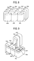
- a core coil assembly is composed of the eight unit cores 50a to 50h and the three coils 40a to 40c, as shown in FIG. 8 .
- Each of the unit cores has a U-shaped cross-section so as to permit its insertion into the coils. After insertion, the ends are closed (subjected to wrapping operation), thereby assembling the core and the coil.
- each of the unit cores 50a to 50h is opened on one side.
- the unit core of an inverted U-shape is inserted into the corresponding coil, and the opened portion is wrapped to assemble the core and the coil.
- the coil bobbins are made of metal such as iron and formed in hollow square poles. As described above, two bobbins for each coil are arranged side by side.
- FIG. 10 shows a horizontal sectional view of the related art core coil assembly shown in FIG. 8 .
- the coils of three phases are formed of the outer secondary coils 40a, 40b, and 40c and primary coils 40d, 40e, and 40f.
- the bobbins with two bobbins for each coil arranged side by side, are installed in the coils. More specifically, the bobbins 60a and 60b are installed in the coils 40a and 40d, the bobbins 60c and 60d are installed in the coils 40b and 40e, and the bobbins 60e and 60f are installed in the coils 40c and 40f. Then the amorphous cores are inserted into the bobbins.
- the core 50a is inserted into one side of the bobbin 60a installed in the coils 40a and 40d on the left side in FIG. 10 , and the core 50b is inserted into one side of the bobbin 60b.
- the cores 50a and 50b are inserted into one side of the bobbins 60a and 60b, respectively, in such a manner that the cores 50a and 50b of the inverted U-shapes straddle the left edges of the coils 40a and 40d. Then left portions of the cores 50a and 50b located outside of the coil 40a are received by an E-shaped clamp 70 so as to keep their assembled conditions, and thereafter held and fixed from above by a U-shaped clamp 80.
- This construction on the left side is applied in the same manner to the cores 50g and 50h on the right side to fix the cores 50g and 50h.
- the core 50c on the left-center lower side is inserted into the other side of the bobbin 60a and one side of the bobbin 60c installed in the coils 40a and 40d and the coils 40b and 40e, respectively, in such a manner as to straddle the portion where the coils 40a and 40d and the coils 40b and 40e are adjacent to each other.
- the core 50d on the left-center upper side is inserted into the other side of the bobbin 60b and one side of the bobbin 60d installed in the coils 40a and 40d and the coils 40b and 40e, respectively, in such a manner as to straddle the portion where the coils 40a and 40d and the coils 40b and 40e are adjacent to each other.
- the core 50e on the right-center lower side is inserted into the other side of the bobbin 60c and one side of the bobbin 60e installed in the coils 40b and 40e and the coils 40c and 40f, respectively, in such a manner as to straddle the portion where the coils 40b and 40e and the coils 40c and 40f are adjacent to each other.
- the core 50f on the right-center upper side is inserted into the other side of the bobbin 60d and one side of the bobbin 60f installed in coils 40b and 40e and the coils 40c and 40f, respectively.
- the core 50g on the right side is inserted into the other side of the bobbin 60e installed in the coils 40c and 40f and a portion of the E-shaped clamp 70 installed outside the coils 40c and 40f, in such a manner as to straddle the right edge portions of the coils 40c and 40f.
- the core 50h is inserted into the other side of the bobbin 60f installed in the coils 40c and 40f and a portion of the E-shaped clamp 70 installed outside the coils 40c and 40f, in such a manner as to straddle the right edge portions of the coils 40c and 40f.
- the cores 50g and 50h received by the E-shaped clamp 70 are fixed from above by the U-shaped clamp 80.
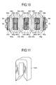
- FIGS. 11 and 12 the related art core and bobbins are shown in FIGS. 11 and 12 .
- FIG. 11 shows the inverted U-shaped core 50a with one end of the unit core opened.
- two rows of the cores having the same width as described above are inserted into the two bobbins 60a and 60b arranged side by side as shown in FIG. 12 so as to compose the core coil assembly.
- the eight unit cores made of the amorphous magnetic strips having the same width are aligned in two rows as described above to compose the amorphous core transformer.
- a preferred aim of the present invention is to provide an amorphous core transformer having an amorphous core construction with improved operating efficiency while obtaining more amorphous core cross-sectional area in the assembly operation of a core coil assembly of a large-capacity amorphous core transformer.
- an amorphous core transformer stores a core coil assembly.
- the core coil assembly includes: an amorphous core composed of amorphous magnetic strips; and a coil for allowing insertion of the amorphous core.
- the amorphous core is constructed such that, when plural kinds of the amorphous magnetic strips having different widths are arranged in abutting relation and laminated, the amorphous magnetic strips are alternated in arrangement for lamination so that abutting surfaces of the arranged and laminated amorphous magnetic strips are displaced with respect to one another.
- the wrapping work can be carried out at one time, leading to an improvement in working efficiency.
- a single bobbin per each coil is disposed.
- the need for partitions is eliminated, and therefore the bobbin and coil can be miniaturized.
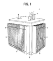
- FIG. 1 is a perspective view showing the external appearance of an amorphous core transformer mounted with amorphous cores according to a first embodiment of the present invention.
- an amorphous core transformer 1 has a structure in which wavy ribs 3 are provided on peripheral edges of a tank container 2 that contains insulating oil for insulating and cooling the amorphous cores and coils attached to the amorphous cores, for cooling heat generated from the coils, the cores, etc.
- reference sign 9 denotes weld lines that are welded and fixed to upper and lower portions of each of the wavy ribs 3 to produce the resistance of the wavy ribs 3 to deformation.
- Reference sign 7 denotes a primary terminal that is installed on an upper portion of the tank container 2 to connect high-voltage power transmitted from a power plant.
- Reference sign 8 denotes a secondary terminal that is installed on an upper portion of the tank container 2 to provide the connection for sending the voltage raised or reduced by the transformer to a load side.
- FIG. 2 is a perspective view showing the core coil assembly mounted with the amorphous cores and bobbins according to this embodiment.
- the amorphous core transformer 1 is a three-phase five-legged core transformer, and there is shown the state in which three coils (4a, 4b, and 4c) are installed, and amorphous cores 5a, 5b, 5c, and 5d are inserted into the coils 4a, 4b, and 4c and wrapped.
- a line on a surface of each of the amorphous cores 5a to 5d is the abutment line between the amorphous magnetic strips that form each of the amorphous cores 5a to 5d. It should be noted that the magnetic strip abutment lines of two adjacent cores differ in position from each other for emphasizing the difference in core width, however, such alternation of the core surfaces as shown in FIG. 2 are not always necessary.
- FIG. 3 shows the assembling process for assembling the cores and coils according to this embodiment, wherein reference signs 5a to 5c denote the amorphous cores; 4a to 4c, the coils; and 6, a bobbin installed in each coil.
- FIG. 3 shows that the amorphous core 5c is in the process of being inserted into the coil 4c with the amorphous cores 5a and 5b disposed inside the coils 4a and 4b.
- each of the amorphous cores 5a to 5c is constructed by bringing the amorphous magnetic strips of different widths into abutting relation to each other and alternately laminating the magnetic strips of different widths. The details will be described later in FIG. 4 .
- the core of this embodiment has a construction in which the two magnetic strips having different widths are integral with each other, unlike the related art construction as shown in FIG. 9 in which the magnetic strips having the same width are arranged in two rows.
- the wrapping work of open ends of the amorphous cores 5a to 5d after inserting the amorphous cores 5a to 5d into the coils 4a to 4c can be cut in almost half relative to the related art.
- the bobbins 6 installed in the coils 4a to 4c can be reduced from two bobbins per coil to a single bobbin per coil. Therefore, it is possible to reduce the cost of bobbin materials and downsize the bobbins while ensuring the cross-sectional area of the amorphous core. Consequently, the whole transformer can be downsized.
- FIG. 4 is a perspective view of the state in which the amorphous cores are peeled away inwardly from the surface according to blocks.
- the amorphous core is formed by use of two kinds of blocks having different amorphous magnetic strip widths (namely, a small width L1 and a large width L2, the relationship of L1 ⁇ L2 is established), and the laminated state thereof will be described in order, from a fourth layer counting inwardly from the surface.
- an amorphous core 5a-7 of the large width L2 on the left side and an amorphous core 5a-8 of the small width L1 on the right side are arranged in abutting relation and laminated to form the fourth layer.
- an amorphous core 5a-5 of the small width L1 on the left side and an amorphous core 5a-6 of the large width L2 on the right side are arranged in abutting relation and laminated on the fourth layer to form a third layer counting inwardly from the surface.
- an amorphous core 5a-3 of the large width L2 on the left side and an amorphous core 5a-4 of the small width L1 on the right side are arranged in abutting relation and laminated on the third layer to form a second layer counting inwardly from the surface.
- an amorphous core 5a-1 of the small width L1 on the left side and an amorphous core 5a-2 of the large width L2 on the right side are arranged in abutting relation and laminated on the second layer to form a surface layer.
- the amorphous cores of the blocks having different widths of each layer abut against each other for lamination. Since the amorphous magnetic strips having different widths are alternately laminated, the abutting surfaces can be displaced with respect to one another. Therefore, the whole laminated cores can be integrated and regarded as a single-piece core.
- FIG. 5 is a perspective view of a bobbin installed in each coil.
- the bobbin 6 of this embodiment into which the amorphous core shown in FIG. 4 is inserted, has one insertion opening and is of a rectangular, hollow square pole shape.
- the bobbin 6 is made of metal material.
- the two bobbins are arranged as shown in FIG. 12 .
- the single bobbin is disposed.
- an amorphous core is formed by using three amorphous magnetic strips so as to obtain more amorphous core width.
- FIG. 6A is a perspective view of the state in which the amorphous core composed of two amorphous magnetic strips having the large width L3 the same as each other and one amorphous magnetic strip having the small width L4 is peeled away inwardly from its surface according to blocks.
- an amorphous core 5a-19 of the small width L4 on the left side and an amorphous core 5a-20 of the large width L3 in the center abut against each other, and the amorphous core 5a-20 of the large width L3 in the center and an amorphous core 5a-21 of the large width L3 on the right side abut against each other to form the fourth layer.
- the amorphous core of the small width L4 on the left side is moved to the right side.
- an amorphous core 5a-16 of the large width L3 on the left side and an amorphous core 5a-17 of the large width L3 in the center abutting against each other
- the amorphous core 5a-17 of the large width L3 in the center and an amorphous core 5a-18 of the small width L4 on the right side abutting against each other, they are laminated on the fourth layer to form a third layer counting inwardly from the surface.
- the amorphous core of the small width L4 on the right side is moved to the left side.
- an amorphous core 5a-13 of the small width L4 on the left side and an amorphous core 5a-14 of the large width L3 in the center abutting against each other
- the amorphous core 5a-14 of the large width L3 in the center and an amorphous core 5a-15 of the large width L3 on the right side abutting against each other, they are laminated on the third layer to form a second layer counting inwardly from the surface.
- the amorphous core of the small width L4 on the left side is moved to the right side.
- an amorphous core 5a-10 of the large width L3 on the left side and an amorphous core 5a-11 of the large width L3 in the center abutting against each other
- the amorphous core 5a-11 of the large width L3 in the center and an amorphous core 5a-12 of the small width L4 on the right side abutting against each other, they are laminated on the second layer to form a surface layer.
- the abutting surfaces T9 and T7 are displaced with respect to each other, and the abutting surfaces T10 and T8 are also displaced with respect to each other.
- the abutting surfaces T7 and T5 are displaced with respect to each other, and the abutting surfaces T8 and T6 are also displaced with respect to each other.
- the amorphous cores of the blocks having different widths of each layer abut against one another and are sequentially laminated.
- the magnetic strips are disposed such that the abutting surfaces of adjacent magnetic strips in a lamination direction are displaced with respect to each other. Therefore, the whole laminated cores can be integrated and regarded as a single-piece core.
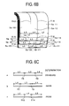
- FIG. 6B a modification of the second embodiment of the present invention will be described with reference to FIG. 6B , in which, in the case of using three amorphous magnetic strips the same as those shown in FIG. 6A , the abutting surfaces of the magnetic strips cannot be displaced with respect to each other.
- the amorphous core 5a-20 of the large width L3 on the left side and the amorphous core 5a-19 of the small width L4 in the center abut against each other, and further, the amorphous core 5a-19 of the small width L4 in the center and the amorphous core 5a-21 of the large width L3 on the right side abut against each other to form the core of the fourth layer.
- the amorphous core of the small width L4 in the center is moved to the right side. Then with the amorphous core 5a-16 of the large width L3 on the left side and the amorphous core 5a-17 of the large width L3 in the center abutting against each other, and further, with the amorphous core 5a-17 of the large width L3 in the center and the amorphous core 5a-18 of the small width L4 on the right side abutting against each other, they are laminated on the fourth layer to form a third layer counting inwardly from the surface.
- the amorphous core of the small width L4 on the right side is moved to the left side.
- the amorphous core 5a-13 of the small width L4 on the left side and the amorphous core 5a-14 of the large width L3 in the center abutting against each other, and further, with the amorphous core 5a-14 of the large width L3 in the center and the amorphous core 5a-15 of the large width L3 on the right side abutting against each other, they are laminated on the third layer to form a second layer counting inwardly from the surface.
- the amorphous core of the small width L4 on the left side is moved to the center. Then with the amorphous core 5a-10 of the large width L3 on the left side and the amorphous core 5a-12 of the small width L4 in the center abutting against each other, and further, with the amorphous core 5a-12 of the small width L4 in the center and the amorphous core 5a-11 of the large width L3 on the right side abutting against each other, they are laminated on the second layer to form a surface layer.
- the abutting surfaces T15 and T17 are displaced with respect to each other, and the abutting surfaces T16 and T18 are also displaced with respect to each other.
- the abutting surfaces T13 and T15 are displaced with respect to each other, while the abutting surfaces T14 and T16 are aligned in the same position.
- FIGS. 6A and 6B are summarized in FIG. 6C .
- FIG. 6C shows magnetic strip layout patterns in the case where an amorphous core is constructed using three magnetic strips (two magnetic strips of the large width L3 of the same size and one magnetic strip of the small width L4).
- FIG. 6C shows a standard layout pattern in which a magnetic strip of the large width L3 disposed on the left side and a magnetic strip of the large width L3 disposed in the center abut against each other, and further, the magnetic strip of the large width L3 disposed in the center and a magnetic strip of the small width L4 disposed on the right side abut against each other.
- layout patterns of the three magnetic strips include two patterns of layouts (b) and (c).
- the layout (b) shows a layout pattern in which a magnetic strip of the small width L4 disposed on the left side and a magnetic strip of the large width L3 disposed in the center abut against each other, and further, the magnetic strip of the large width L3 disposed in the center and a magnetic strip of the large width L3 disposed on the right side abut against each other.
- the layout (c) shows a layout pattern in which a magnetic strip of the large width L3 disposed on the left side and a magnetic strip of the small width L4 disposed in the center abut against each other, and further, the magnetic strip of the small width L4 in the center and a magnetic strip of the large width L3 on the right side abut against each other.
- the abutting surfaces T7 or T8 of the layout (b) are displaced and misaligned relative to the abutting surfaces T5 and T6 of the layout (a).
- the abutting surface T13 of the layout (c) is aligned with the abutting surface T5 of the layout (a), while the abutting surface T14 of the layout (c) is displaced relative to the abutting surface T6 of the layout (a).
- the layout (a) is used as a standard magnetic film layout
- the abutting surfaces are displaced, while in the magnetic film layout (c), some of the abutting surfaces are aligned.
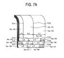
- FIG. 7A shows an amorphous core according to the third embodiment of the present invention, in which the widths of the magnetic strips are set as L5, L6, and L7 and the relationship of L5 ⁇ L6 ⁇ L7 (hereinafter referred to as the small width L5, the medium width L6, and the large width L7) is established.
- an amorphous core 5a-39 of the medium width L6 on the left side and an amorphous core 5a-40 of the large width L7 in the center abut against each other, and further, the amorphous core 5a-40 of the large width L7 in the center and an amorphous core 5a-41 of the small width L5 on the right side abut against each other to form the fourth layer amorphous core.
- the amorphous core of the small width L5 on the right side is moved to the left side. Then an amorphous core 5a-36 of the small width L5 on the left side and an amorphous core 5a-37 of the medium width L6 in the center abut against each other, and further, the amorphous core 5a-37 of the medium width L6 in the center and an amorphous core 5a-38 of the large width L7 on the right side abut against each other to form a third layer on the fourth layer.
- the amorphous core of the small width L5 on the left side is moved to the right side.
- an amorphous core 5a-33 of the medium width L6 on the left side and an amorphous core 5a-34 of the large width L7 in the center abut against each other, and further, the amorphous core 5a-34 of the large width L7 in the center and an amorphous core 5a-35 of the small width L5 on the right side abut against each other to form a second layer on the third layer.
- the amorphous core of the small width L5 on the right side is moved to the left side. Then an amorphous core 5a-30 of the small width L5 on the left side and an amorphous core 5a-31 of the medium width L6 in the center abut against each other, and further, the amorphous core 5a-31 of the medium width L6 in the center and an amorphous core 5a-32 of the large width L7 on the right side abut against each other to form a surface layer on the second layer.
- the abutting surfaces T23, T24, T25, and T26 are displaced and misaligned relative to one another.
- the abutting surfaces T23, T24, T21, and T22 are displaced and misaligned relative to one another.
- FIG. 7B shows a schematic view of the magnetic strip layout that is formed with an amorphous core of the small width L5 on the left side and an amorphous core of the medium width L6 in the center abutting against each other, and further, with the amorphous core of the medium width L6 in the center and an amorphous core of the large width L7 on the right side abutting against each other.
- the layout (a) is used as a standard for comparison of the abutting surfaces in the case of other amorphous core layouts. When the layout (a) is used as a standard, there are five patterns for the layout of the three amorphous magnetic strips.
- an amorphous core of the medium width L6 on the left side and an amorphous core of the large width L7 in the center abut against each other, and further, the amorphous core of the large width L7 in the center and an amorphous core of the small width L5 on the right side abut against each other to form the amorphous core.
- an amorphous core of the narrow width L5 on the left side and an amorphous core of the large width L7 in the center abut against each other, and further, the amorphous core of the large width L7 in the center and an amorphous core of the medium width L6 on the right side abut against each other to form the amorphous core.
- an amorphous core of the medium width L6 on the left side and an amorphous core of the small width L5 in the center abut against each other, and further, the amorphous core of the small width L5 in the center and an amorphous core of the large width L7 on the right side abut against each other to form the amorphous core.
- an amorphous core of the large width L7 on the left side and an amorphous core of the medium width L6 in the center abut against each other, and further, the amorphous core of the medium width L6 in the center and an amorphous core of the small width L5 on the right side abut against each other to form the amorphous core.
- an amorphous core of the large width L7 on the left side and an amorphous core of the small width L5 in the center abut against each other, and further, the amorphous core of the small width L5 in the center and an amorphous core of the medium width L6 on the right side abut against each other to form the amorphous core.
- the magnetic strip layout (a) when used as a standard, the abutting surfaces of adjacent magnetic strips in the lamination direction are displaced and misaligned relative to each other.
- the cores when the amorphous cores are assembled by alternately laminating the amorphous magnetic strips, the cores can be integrated and regarded as a single-piece core.
Landscapes
- Engineering & Computer Science (AREA)
- Power Engineering (AREA)
- Manufacturing & Machinery (AREA)
- Manufacturing Cores, Coils, And Magnets (AREA)
- Soft Magnetic Materials (AREA)
Applications Claiming Priority (1)
| Application Number | Priority Date | Filing Date | Title |
|---|---|---|---|
| JP2011239840A JP5676414B2 (ja) | 2011-11-01 | 2011-11-01 | アモルファス鉄心変圧器 |
Publications (3)
| Publication Number | Publication Date |
|---|---|
| EP2590186A2 true EP2590186A2 (de) | 2013-05-08 |
| EP2590186A3 EP2590186A3 (de) | 2016-01-06 |
| EP2590186B1 EP2590186B1 (de) | 2017-01-11 |
Family
ID=46754306
Family Applications (1)
| Application Number | Title | Priority Date | Filing Date |
|---|---|---|---|
| EP12179341.8A Not-in-force EP2590186B1 (de) | 2011-11-01 | 2012-08-06 | Transformator mit amorphem Kern |
Country Status (4)
| Country | Link |
|---|---|
| US (1) | US9601255B2 (de) |
| EP (1) | EP2590186B1 (de) |
| JP (1) | JP5676414B2 (de) |
| CN (2) | CN106057436B (de) |
Cited By (1)
| Publication number | Priority date | Publication date | Assignee | Title |
|---|---|---|---|---|
| EP3503139A1 (de) * | 2017-12-20 | 2019-06-26 | Bertram Ehmann | Verfahren und halbzeug zum herstellen von wenigstens einem paketabschnitt eines weichmagnetischen bauteils sowie paketabschnitt und weichmagnetisches bauteil |
Families Citing this family (7)
| Publication number | Priority date | Publication date | Assignee | Title |
|---|---|---|---|---|
| JP6045839B2 (ja) * | 2012-07-27 | 2016-12-14 | 株式会社日立産機システム | アモルファス鉄心変圧器の製造方法 |
| US20170352466A1 (en) * | 2015-05-27 | 2017-12-07 | Hitachi Industrial Equipment Systems Co., Ltd. | Laminated Iron Core Structure and Transformer Including the Same |
| JP6454634B2 (ja) * | 2015-11-25 | 2019-01-16 | 株式会社日立産機システム | アモルファス変圧器及びアモルファス鉄心 |
| JP6655525B2 (ja) * | 2016-11-18 | 2020-02-26 | 株式会社日立産機システム | 変圧器、鉄心及びアモルファス金属部材 |
| JP7356785B2 (ja) * | 2017-05-24 | 2023-10-05 | 株式会社日立産機システム | 変圧器及びアモルファス薄帯 |
| JP7501888B2 (ja) * | 2020-03-06 | 2024-06-18 | 北川工業株式会社 | 環状磁性体 |
| WO2024106262A1 (ja) * | 2022-11-16 | 2024-05-23 | Ecdl合同会社 | 複合積層軟磁性薄帯 |
Family Cites Families (13)
| Publication number | Priority date | Publication date | Assignee | Title |
|---|---|---|---|---|
| US3183461A (en) * | 1962-02-05 | 1965-05-11 | Westinghouse Electric Corp | Magnetic core structure with cooling passages therein |
| JPH09246057A (ja) * | 1996-03-06 | 1997-09-19 | Daihen Corp | アモルファス巻鉄心 |
| JP3317877B2 (ja) * | 1997-06-06 | 2002-08-26 | 株式会社日立製作所 | アモルファス巻鉄心変圧器 |
| TW371768B (en) * | 1997-06-06 | 1999-10-11 | Hitachi Ltd | Amorphous transformer |
| JP4358119B2 (ja) | 1998-06-29 | 2009-11-04 | 株式会社日立産機システム | アモルファス鉄心変圧器 |
| DE69922094T2 (de) | 1998-07-31 | 2005-12-01 | Hitachi, Ltd. | Transformatorkern aus amorphem Metall |
| CN101447283A (zh) * | 2008-05-30 | 2009-06-03 | 北京中机联供非晶科技股份有限公司 | 截面近似圆的搭接式三相五柱式非晶铁心装置 |
| JP5161039B2 (ja) * | 2008-11-11 | 2013-03-13 | 株式会社日立産機システム | 変圧器用のコイル巻枠及びそれを用いた変圧器 |
| CN101937760B (zh) * | 2009-06-30 | 2015-07-01 | 上海市电力公司 | 一种变压器器身 |
| CN201594448U (zh) * | 2009-11-19 | 2010-09-29 | 华通机电集团有限公司 | 一种非晶合金变压器 |
| JP5426356B2 (ja) * | 2009-12-22 | 2014-02-26 | タカオカ化成工業株式会社 | 巻鉄心及びその組み立て方法 |
| JP5425114B2 (ja) * | 2011-01-14 | 2014-02-26 | 株式会社日立産機システム | アモルファス巻鉄心変圧器 |
| CN203055610U (zh) * | 2013-01-21 | 2013-07-10 | 广州广高高压电器有限公司 | 一种非晶合金立体三角形开口式卷铁心 |
-
2011
- 2011-11-01 JP JP2011239840A patent/JP5676414B2/ja active Active
-
2012
- 2012-08-06 EP EP12179341.8A patent/EP2590186B1/de not_active Not-in-force
- 2012-08-08 US US13/569,229 patent/US9601255B2/en not_active Expired - Fee Related
- 2012-08-10 CN CN201610329571.9A patent/CN106057436B/zh not_active Expired - Fee Related
- 2012-08-10 CN CN201210284590.6A patent/CN103093933B/zh not_active Expired - Fee Related
Non-Patent Citations (1)
| Title |
|---|
| None |
Cited By (1)
| Publication number | Priority date | Publication date | Assignee | Title |
|---|---|---|---|---|
| EP3503139A1 (de) * | 2017-12-20 | 2019-06-26 | Bertram Ehmann | Verfahren und halbzeug zum herstellen von wenigstens einem paketabschnitt eines weichmagnetischen bauteils sowie paketabschnitt und weichmagnetisches bauteil |
Also Published As
| Publication number | Publication date |
|---|---|
| EP2590186A3 (de) | 2016-01-06 |
| JP5676414B2 (ja) | 2015-02-25 |
| CN106057436A (zh) | 2016-10-26 |
| CN103093933B (zh) | 2016-06-15 |
| JP2013098349A (ja) | 2013-05-20 |
| CN106057436B (zh) | 2017-09-26 |
| US9601255B2 (en) | 2017-03-21 |
| EP2590186B1 (de) | 2017-01-11 |
| US20130106555A1 (en) | 2013-05-02 |
| CN103093933A (zh) | 2013-05-08 |
Similar Documents
| Publication | Publication Date | Title |
|---|---|---|
| EP2590186A2 (de) | Transformator mit amorphem Kern | |
| EP0977214B1 (de) | Transformatorkern aus amorphem Metall | |
| US7961072B2 (en) | Inductive element | |
| EP2859564B1 (de) | Dreistufiger kern für einen nichtlinearen transformator | |
| EP3306626A1 (de) | Gestapelte kernstruktur und transformator damit | |
| EP3159903B1 (de) | Resonanter transformator mit hoher stromdichte | |
| CN104851563A (zh) | 应用于电抗器的磁芯以及电抗器 | |
| EP3288047A1 (de) | Resonanter transformator mit verbesserter struktur mit hoher stromdichte | |
| EP1730753B1 (de) | Folienwicklung mit niedrigem wechselstromwiderstand für magnetspulen auf kernen mit lücken | |
| US20140266535A1 (en) | Low loss inductor with offset gap and windings | |
| WO2009109689A1 (en) | Disc winding | |
| EP2530688A1 (de) | Flachbandaufwicklung für einen Drosselspulenkern | |
| US9123461B2 (en) | Reconfiguring tape wound cores for inductors | |
| US20190139697A1 (en) | Magnetic element, metal annular winding and method for manufacturing the same | |
| US7872390B2 (en) | Method for manufacturing a conductor bar of a rotating electrical machine and a conductor bar manufactured according to this method | |
| JP4845199B2 (ja) | トランス | |
| CN101147214B (zh) | 具有带十字形芯柱的层叠芯的变压器及其制造方法 | |
| JP6466728B2 (ja) | 変圧器およびその製造方法 | |
| JP2002093633A (ja) | トランス | |
| KR101506698B1 (ko) | 변압기용 철심 권선 조립체 | |
| US9251939B1 (en) | Stationary induction electric apparatus | |
| CN110310805A (zh) | 多层结构电磁设备 | |
| JP2002222724A (ja) | コイルの製造方法 | |
| EP4390988A1 (de) | Elektromagnetische stahlplatte für einen reaktor und reaktor | |
| KR20190003920A (ko) | 변압기용 평판형 코일 |
Legal Events
| Date | Code | Title | Description |
|---|---|---|---|
| PUAI | Public reference made under article 153(3) epc to a published international application that has entered the european phase |
Free format text: ORIGINAL CODE: 0009012 |
|
| 17P | Request for examination filed |
Effective date: 20120824 |
|
| AK | Designated contracting states |
Kind code of ref document: A2 Designated state(s): AL AT BE BG CH CY CZ DE DK EE ES FI FR GB GR HR HU IE IS IT LI LT LU LV MC MK MT NL NO PL PT RO RS SE SI SK SM TR |
|
| AX | Request for extension of the european patent |
Extension state: BA ME |
|
| PUAL | Search report despatched |
Free format text: ORIGINAL CODE: 0009013 |
|
| AK | Designated contracting states |
Kind code of ref document: A3 Designated state(s): AL AT BE BG CH CY CZ DE DK EE ES FI FR GB GR HR HU IE IS IT LI LT LU LV MC MK MT NL NO PL PT RO RS SE SI SK SM TR |
|
| AX | Request for extension of the european patent |
Extension state: BA ME |
|
| RIC1 | Information provided on ipc code assigned before grant |
Ipc: H01F 41/02 20060101ALI20151201BHEP Ipc: H01F 27/25 20060101AFI20151201BHEP |
|
| GRAP | Despatch of communication of intention to grant a patent |
Free format text: ORIGINAL CODE: EPIDOSNIGR1 |
|
| INTG | Intention to grant announced |
Effective date: 20160818 |
|
| GRAS | Grant fee paid |
Free format text: ORIGINAL CODE: EPIDOSNIGR3 |
|
| GRAA | (expected) grant |
Free format text: ORIGINAL CODE: 0009210 |
|
| AK | Designated contracting states |
Kind code of ref document: B1 Designated state(s): AL AT BE BG CH CY CZ DE DK EE ES FI FR GB GR HR HU IE IS IT LI LT LU LV MC MK MT NL NO PL PT RO RS SE SI SK SM TR |
|
| REG | Reference to a national code |
Ref country code: GB Ref legal event code: FG4D |
|
| REG | Reference to a national code |
Ref country code: CH Ref legal event code: EP |
|
| REG | Reference to a national code |
Ref country code: AT Ref legal event code: REF Ref document number: 861942 Country of ref document: AT Kind code of ref document: T Effective date: 20170115 |
|
| REG | Reference to a national code |
Ref country code: IE Ref legal event code: FG4D |
|
| REG | Reference to a national code |
Ref country code: DE Ref legal event code: R096 Ref document number: 602012027647 Country of ref document: DE |
|
| REG | Reference to a national code |
Ref country code: LT Ref legal event code: MG4D |
|
| REG | Reference to a national code |
Ref country code: NL Ref legal event code: MP Effective date: 20170111 |
|
| REG | Reference to a national code |
Ref country code: AT Ref legal event code: MK05 Ref document number: 861942 Country of ref document: AT Kind code of ref document: T Effective date: 20170111 |
|
| PG25 | Lapsed in a contracting state [announced via postgrant information from national office to epo] |
Ref country code: NL Free format text: LAPSE BECAUSE OF FAILURE TO SUBMIT A TRANSLATION OF THE DESCRIPTION OR TO PAY THE FEE WITHIN THE PRESCRIBED TIME-LIMIT Effective date: 20170111 |
|
| PG25 | Lapsed in a contracting state [announced via postgrant information from national office to epo] |
Ref country code: GR Free format text: LAPSE BECAUSE OF FAILURE TO SUBMIT A TRANSLATION OF THE DESCRIPTION OR TO PAY THE FEE WITHIN THE PRESCRIBED TIME-LIMIT Effective date: 20170412 Ref country code: FI Free format text: LAPSE BECAUSE OF FAILURE TO SUBMIT A TRANSLATION OF THE DESCRIPTION OR TO PAY THE FEE WITHIN THE PRESCRIBED TIME-LIMIT Effective date: 20170111 Ref country code: IS Free format text: LAPSE BECAUSE OF FAILURE TO SUBMIT A TRANSLATION OF THE DESCRIPTION OR TO PAY THE FEE WITHIN THE PRESCRIBED TIME-LIMIT Effective date: 20170511 Ref country code: LT Free format text: LAPSE BECAUSE OF FAILURE TO SUBMIT A TRANSLATION OF THE DESCRIPTION OR TO PAY THE FEE WITHIN THE PRESCRIBED TIME-LIMIT Effective date: 20170111 Ref country code: HR Free format text: LAPSE BECAUSE OF FAILURE TO SUBMIT A TRANSLATION OF THE DESCRIPTION OR TO PAY THE FEE WITHIN THE PRESCRIBED TIME-LIMIT Effective date: 20170111 Ref country code: NO Free format text: LAPSE BECAUSE OF FAILURE TO SUBMIT A TRANSLATION OF THE DESCRIPTION OR TO PAY THE FEE WITHIN THE PRESCRIBED TIME-LIMIT Effective date: 20170411 |
|
| PG25 | Lapsed in a contracting state [announced via postgrant information from national office to epo] |
Ref country code: BG Free format text: LAPSE BECAUSE OF FAILURE TO SUBMIT A TRANSLATION OF THE DESCRIPTION OR TO PAY THE FEE WITHIN THE PRESCRIBED TIME-LIMIT Effective date: 20170411 Ref country code: RS Free format text: LAPSE BECAUSE OF FAILURE TO SUBMIT A TRANSLATION OF THE DESCRIPTION OR TO PAY THE FEE WITHIN THE PRESCRIBED TIME-LIMIT Effective date: 20170111 Ref country code: SE Free format text: LAPSE BECAUSE OF FAILURE TO SUBMIT A TRANSLATION OF THE DESCRIPTION OR TO PAY THE FEE WITHIN THE PRESCRIBED TIME-LIMIT Effective date: 20170111 Ref country code: PL Free format text: LAPSE BECAUSE OF FAILURE TO SUBMIT A TRANSLATION OF THE DESCRIPTION OR TO PAY THE FEE WITHIN THE PRESCRIBED TIME-LIMIT Effective date: 20170111 Ref country code: LV Free format text: LAPSE BECAUSE OF FAILURE TO SUBMIT A TRANSLATION OF THE DESCRIPTION OR TO PAY THE FEE WITHIN THE PRESCRIBED TIME-LIMIT Effective date: 20170111 Ref country code: PT Free format text: LAPSE BECAUSE OF FAILURE TO SUBMIT A TRANSLATION OF THE DESCRIPTION OR TO PAY THE FEE WITHIN THE PRESCRIBED TIME-LIMIT Effective date: 20170511 Ref country code: ES Free format text: LAPSE BECAUSE OF FAILURE TO SUBMIT A TRANSLATION OF THE DESCRIPTION OR TO PAY THE FEE WITHIN THE PRESCRIBED TIME-LIMIT Effective date: 20170111 Ref country code: AT Free format text: LAPSE BECAUSE OF FAILURE TO SUBMIT A TRANSLATION OF THE DESCRIPTION OR TO PAY THE FEE WITHIN THE PRESCRIBED TIME-LIMIT Effective date: 20170111 |
|
| REG | Reference to a national code |
Ref country code: DE Ref legal event code: R097 Ref document number: 602012027647 Country of ref document: DE |
|
| PG25 | Lapsed in a contracting state [announced via postgrant information from national office to epo] |
Ref country code: SK Free format text: LAPSE BECAUSE OF FAILURE TO SUBMIT A TRANSLATION OF THE DESCRIPTION OR TO PAY THE FEE WITHIN THE PRESCRIBED TIME-LIMIT Effective date: 20170111 Ref country code: EE Free format text: LAPSE BECAUSE OF FAILURE TO SUBMIT A TRANSLATION OF THE DESCRIPTION OR TO PAY THE FEE WITHIN THE PRESCRIBED TIME-LIMIT Effective date: 20170111 Ref country code: CZ Free format text: LAPSE BECAUSE OF FAILURE TO SUBMIT A TRANSLATION OF THE DESCRIPTION OR TO PAY THE FEE WITHIN THE PRESCRIBED TIME-LIMIT Effective date: 20170111 Ref country code: IT Free format text: LAPSE BECAUSE OF FAILURE TO SUBMIT A TRANSLATION OF THE DESCRIPTION OR TO PAY THE FEE WITHIN THE PRESCRIBED TIME-LIMIT Effective date: 20170111 Ref country code: RO Free format text: LAPSE BECAUSE OF FAILURE TO SUBMIT A TRANSLATION OF THE DESCRIPTION OR TO PAY THE FEE WITHIN THE PRESCRIBED TIME-LIMIT Effective date: 20170111 |
|
| PLBE | No opposition filed within time limit |
Free format text: ORIGINAL CODE: 0009261 |
|
| STAA | Information on the status of an ep patent application or granted ep patent |
Free format text: STATUS: NO OPPOSITION FILED WITHIN TIME LIMIT |
|
| PG25 | Lapsed in a contracting state [announced via postgrant information from national office to epo] |
Ref country code: SM Free format text: LAPSE BECAUSE OF FAILURE TO SUBMIT A TRANSLATION OF THE DESCRIPTION OR TO PAY THE FEE WITHIN THE PRESCRIBED TIME-LIMIT Effective date: 20170111 Ref country code: DK Free format text: LAPSE BECAUSE OF FAILURE TO SUBMIT A TRANSLATION OF THE DESCRIPTION OR TO PAY THE FEE WITHIN THE PRESCRIBED TIME-LIMIT Effective date: 20170111 |
|
| 26N | No opposition filed |
Effective date: 20171012 |
|
| PG25 | Lapsed in a contracting state [announced via postgrant information from national office to epo] |
Ref country code: SI Free format text: LAPSE BECAUSE OF FAILURE TO SUBMIT A TRANSLATION OF THE DESCRIPTION OR TO PAY THE FEE WITHIN THE PRESCRIBED TIME-LIMIT Effective date: 20170111 |
|
| REG | Reference to a national code |
Ref country code: CH Ref legal event code: PL |
|
| PG25 | Lapsed in a contracting state [announced via postgrant information from national office to epo] |
Ref country code: MC Free format text: LAPSE BECAUSE OF FAILURE TO SUBMIT A TRANSLATION OF THE DESCRIPTION OR TO PAY THE FEE WITHIN THE PRESCRIBED TIME-LIMIT Effective date: 20170111 |
|
| GBPC | Gb: european patent ceased through non-payment of renewal fee |
Effective date: 20170806 |
|
| PG25 | Lapsed in a contracting state [announced via postgrant information from national office to epo] |
Ref country code: LI Free format text: LAPSE BECAUSE OF NON-PAYMENT OF DUE FEES Effective date: 20170831 Ref country code: CH Free format text: LAPSE BECAUSE OF NON-PAYMENT OF DUE FEES Effective date: 20170831 |
|
| REG | Reference to a national code |
Ref country code: FR Ref legal event code: ST Effective date: 20180430 |
|
| REG | Reference to a national code |
Ref country code: IE Ref legal event code: MM4A |
|
| REG | Reference to a national code |
Ref country code: BE Ref legal event code: MM Effective date: 20170831 |
|
| PG25 | Lapsed in a contracting state [announced via postgrant information from national office to epo] |
Ref country code: LU Free format text: LAPSE BECAUSE OF NON-PAYMENT OF DUE FEES Effective date: 20170806 |
|
| PG25 | Lapsed in a contracting state [announced via postgrant information from national office to epo] |
Ref country code: IE Free format text: LAPSE BECAUSE OF NON-PAYMENT OF DUE FEES Effective date: 20170806 Ref country code: GB Free format text: LAPSE BECAUSE OF NON-PAYMENT OF DUE FEES Effective date: 20170806 |
|
| PG25 | Lapsed in a contracting state [announced via postgrant information from national office to epo] |
Ref country code: FR Free format text: LAPSE BECAUSE OF NON-PAYMENT OF DUE FEES Effective date: 20170831 Ref country code: BE Free format text: LAPSE BECAUSE OF NON-PAYMENT OF DUE FEES Effective date: 20170831 |
|
| PG25 | Lapsed in a contracting state [announced via postgrant information from national office to epo] |
Ref country code: MT Free format text: LAPSE BECAUSE OF NON-PAYMENT OF DUE FEES Effective date: 20170806 |
|
| PG25 | Lapsed in a contracting state [announced via postgrant information from national office to epo] |
Ref country code: HU Free format text: LAPSE BECAUSE OF FAILURE TO SUBMIT A TRANSLATION OF THE DESCRIPTION OR TO PAY THE FEE WITHIN THE PRESCRIBED TIME-LIMIT; INVALID AB INITIO Effective date: 20120806 |
|
| REG | Reference to a national code |
Ref country code: DE Ref legal event code: R082 Ref document number: 602012027647 Country of ref document: DE Representative=s name: MEWBURN ELLIS LLP, DE |
|
| PG25 | Lapsed in a contracting state [announced via postgrant information from national office to epo] |
Ref country code: CY Free format text: LAPSE BECAUSE OF NON-PAYMENT OF DUE FEES Effective date: 20170111 |
|
| PG25 | Lapsed in a contracting state [announced via postgrant information from national office to epo] |
Ref country code: MK Free format text: LAPSE BECAUSE OF FAILURE TO SUBMIT A TRANSLATION OF THE DESCRIPTION OR TO PAY THE FEE WITHIN THE PRESCRIBED TIME-LIMIT Effective date: 20170111 |
|
| PG25 | Lapsed in a contracting state [announced via postgrant information from national office to epo] |
Ref country code: TR Free format text: LAPSE BECAUSE OF FAILURE TO SUBMIT A TRANSLATION OF THE DESCRIPTION OR TO PAY THE FEE WITHIN THE PRESCRIBED TIME-LIMIT Effective date: 20170111 |
|
| PG25 | Lapsed in a contracting state [announced via postgrant information from national office to epo] |
Ref country code: AL Free format text: LAPSE BECAUSE OF FAILURE TO SUBMIT A TRANSLATION OF THE DESCRIPTION OR TO PAY THE FEE WITHIN THE PRESCRIBED TIME-LIMIT Effective date: 20170111 |
|
| PGFP | Annual fee paid to national office [announced via postgrant information from national office to epo] |
Ref country code: DE Payment date: 20200722 Year of fee payment: 9 |
|
| REG | Reference to a national code |
Ref country code: DE Ref legal event code: R119 Ref document number: 602012027647 Country of ref document: DE |
|
| PG25 | Lapsed in a contracting state [announced via postgrant information from national office to epo] |
Ref country code: DE Free format text: LAPSE BECAUSE OF NON-PAYMENT OF DUE FEES Effective date: 20220301 |