EP2590231A2 - Kondensorlinse und Photovoltaikssystem damit - Google Patents
Kondensorlinse und Photovoltaikssystem damit Download PDFInfo
- Publication number
- EP2590231A2 EP2590231A2 EP11195216.4A EP11195216A EP2590231A2 EP 2590231 A2 EP2590231 A2 EP 2590231A2 EP 11195216 A EP11195216 A EP 11195216A EP 2590231 A2 EP2590231 A2 EP 2590231A2
- Authority
- EP
- European Patent Office
- Prior art keywords
- annular
- lens body
- prism
- power system
- lens
- Prior art date
- Legal status (The legal status is an assumption and is not a legal conclusion. Google has not performed a legal analysis and makes no representation as to the accuracy of the status listed.)
- Withdrawn
Links
- 239000000463 material Substances 0.000 claims description 16
- 150000001875 compounds Chemical class 0.000 claims description 4
- 229910021421 monocrystalline silicon Inorganic materials 0.000 claims description 4
- 229910021420 polycrystalline silicon Inorganic materials 0.000 claims description 4
- 229910021417 amorphous silicon Inorganic materials 0.000 claims description 3
- 239000004065 semiconductor Substances 0.000 claims description 3
- 238000010586 diagram Methods 0.000 description 12
- 238000005286 illumination Methods 0.000 description 10
- 238000006243 chemical reaction Methods 0.000 description 9
- 239000004793 Polystyrene Substances 0.000 description 4
- ADFPJHOAARPYLP-UHFFFAOYSA-N methyl 2-methylprop-2-enoate;styrene Chemical compound COC(=O)C(C)=C.C=CC1=CC=CC=C1 ADFPJHOAARPYLP-UHFFFAOYSA-N 0.000 description 4
- 239000004417 polycarbonate Substances 0.000 description 4
- 229920000642 polymer Polymers 0.000 description 4
- 239000012141 concentrate Substances 0.000 description 3
- 230000003247 decreasing effect Effects 0.000 description 3
- 238000011160 research Methods 0.000 description 3
- CERQOIWHTDAKMF-UHFFFAOYSA-M Methacrylate Chemical compound CC(=C)C([O-])=O CERQOIWHTDAKMF-UHFFFAOYSA-M 0.000 description 2
- 230000005611 electricity Effects 0.000 description 2
- 239000011521 glass Substances 0.000 description 2
- 238000012986 modification Methods 0.000 description 2
- 230000004048 modification Effects 0.000 description 2
- 229920003229 poly(methyl methacrylate) Polymers 0.000 description 2
- 229920000515 polycarbonate Polymers 0.000 description 2
- 239000004926 polymethyl methacrylate Substances 0.000 description 2
- 229920002223 polystyrene Polymers 0.000 description 2
- 239000012780 transparent material Substances 0.000 description 2
- OKTJSMMVPCPJKN-UHFFFAOYSA-N Carbon Chemical compound [C] OKTJSMMVPCPJKN-UHFFFAOYSA-N 0.000 description 1
- 230000004075 alteration Effects 0.000 description 1
- 238000004458 analytical method Methods 0.000 description 1
- 230000007423 decrease Effects 0.000 description 1
- 230000000694 effects Effects 0.000 description 1
- 238000005516 engineering process Methods 0.000 description 1
- 230000007613 environmental effect Effects 0.000 description 1
- 239000010439 graphite Substances 0.000 description 1
- 229910002804 graphite Inorganic materials 0.000 description 1
- 230000017525 heat dissipation Effects 0.000 description 1
- 238000004519 manufacturing process Methods 0.000 description 1
- 239000007769 metal material Substances 0.000 description 1
- 239000002923 metal particle Substances 0.000 description 1
- 238000000034 method Methods 0.000 description 1
- 230000003287 optical effect Effects 0.000 description 1
- 239000002245 particle Substances 0.000 description 1
- 230000035945 sensitivity Effects 0.000 description 1
Images




Classifications
-
- H—ELECTRICITY
- H10—SEMICONDUCTOR DEVICES; ELECTRIC SOLID-STATE DEVICES NOT OTHERWISE PROVIDED FOR
- H10F—INORGANIC SEMICONDUCTOR DEVICES SENSITIVE TO INFRARED RADIATION, LIGHT, ELECTROMAGNETIC RADIATION OF SHORTER WAVELENGTH OR CORPUSCULAR RADIATION
- H10F77/00—Constructional details of devices covered by this subclass
- H10F77/40—Optical elements or arrangements
- H10F77/42—Optical elements or arrangements directly associated or integrated with photovoltaic cells, e.g. light-reflecting means or light-concentrating means
- H10F77/484—Refractive light-concentrating means, e.g. lenses
-
- Y—GENERAL TAGGING OF NEW TECHNOLOGICAL DEVELOPMENTS; GENERAL TAGGING OF CROSS-SECTIONAL TECHNOLOGIES SPANNING OVER SEVERAL SECTIONS OF THE IPC; TECHNICAL SUBJECTS COVERED BY FORMER USPC CROSS-REFERENCE ART COLLECTIONS [XRACs] AND DIGESTS
- Y02—TECHNOLOGIES OR APPLICATIONS FOR MITIGATION OR ADAPTATION AGAINST CLIMATE CHANGE
- Y02E—REDUCTION OF GREENHOUSE GAS [GHG] EMISSIONS, RELATED TO ENERGY GENERATION, TRANSMISSION OR DISTRIBUTION
- Y02E10/00—Energy generation through renewable energy sources
- Y02E10/50—Photovoltaic [PV] energy
- Y02E10/52—PV systems with concentrators
Definitions
- the present invention relates to a condensing lens and a photovoltaic power system.
- the solar energy power system includes the heat power system and the photovoltaic power system.
- the photovoltaic power system is mainly composed of a condensing lens and a photovoltaic chip such as a monocrystalline silicon solar cell, a polycrystalline silicon solar cell, or a III-V compound solar cell.
- the configuration of the condensing lens can concentrate the light energy on the photovoltaic chip for generating electricity. In this case, the solar light can be concentrated by the condensing lens and focused on the photovoltaic chip with smaller area, thereby decreasing the material cost of the photovoltaic chip.
- a conventional photovoltaic power system 1 includes a condensing lens 11 and a photovoltaic chip 12.
- a first surface 111 of the condensing lens 11 is a planar surface, and another surface opposite to the first surface 111 is configured with a plurality of annular protruding structures 112.
- each annular protruding structure 112 has a cross-section similar to a right triangle, and the lengths the annular surfaces S 1 of the annular protruding structures 112 are all the same.
- the annular surface S 1 can be a circle, ellipse, or second-degree parabolic curve.
- the photovoltaic chip 12 is disposed at one side of the condensing lens 11 facing the annular protruding structures 112 and receives the light beams L passing through the condensing lens 11, which can conduct the desired photoelectric conversion.
- the angle of the solar light may change after the time goes by, which can lead the angle shift.
- the conventional condensing lens 11 can not concentrate the light beams on the photovoltaic chip 12. As a result, the efficiency of the photovoltaic power system 1 is sufficiently decreased.
- the sun-tracing system for automatically adjusting the condensing lens 11 and the photovoltaic chip 12 to face the sun directly, thereby maintaining the photoelectric conversion efficiency.
- the power source of the conventional sun-tracing system is usually supplied by the photovoltaic power system 1, so that the net electricity provided by the photovoltaic power system 1 is deceased due to this additional consumption for driving the sun-tracing system.
- an object of the present invention is to provide a condensing lens and photovoltaic power system that can increase the illumination and concentration efficiency, thereby improving the photoelectric conversion efficiency.
- a condensing lens includes a lens body and a prism structure.
- the lens body has a first surface and a second surface opposite to each other.
- the prism structure is disposed on the second surface of the lens body and has a plurality of annular prism units.
- the prism structure has at least two focuses in accordance with the annular prism units, and the focuses are distributed on a plane which is parallel to the first surface of the lens body.
- the lens body and the prism structure comprise the same material.
- the lens body and the prism structure comprise different materials.
- an included angle between an annular surface of the annular prism unit and the second surface of the lens body satisfies the following equation:
- c represents the included angle
- r represents a distance from the annular prism unit to a center point of the lens body
- n represents a refraction index of the annular prism unit
- D represents a focus length of the annular prism unit.
- the first surface of the lens body receives a plurality of light beams, and the light beams pass through the annular surfaces of the annular prism units and are then concentrated at the focuses.
- the present invention also discloses a photovoltaic power system including a condensing lens and a photovoltaic chip.
- the condensing lens includes a lens body and a prism structure.
- the lens body has a first surface and a second surface opposite to each other.
- the prism structure is disposed on the second surface of the lens body and has a plurality of annular prism units.
- the photovoltaic chip is disposed at one side of the condensing lens facing the prism structure.
- the prism structure has at least two focuses in accordance with the annular prism units, and the focuses are distributed on a plane parallel to the first surface of the lens body. The plane is located between the photovoltaic chip and the annular prism units.
- the lens body and the prism structure comprise the same material.
- the lens body and the prism structure comprise different materials.
- the photovoltaic chip is a monocrystalline silicon solar cell, a polycrystalline silicon solar cell, an amorphous silicon solar cell, a compound solar cell, or an organic semiconductor solar cell.
- the photovoltaic power system further includes a light collecting device disposed between the condensing lens and the photovoltaic chip for receiving light beams outputted from an annular surface of each annular prism unit.
- the photovoltaic power system further includes a heat-dissipating device disposed at another side of the photovoltaic chip away from the prism structure.
- an included angle between an annular surface of the annular prism unit and the second surface of the lens body satisfies the following equation:
- c represents the included angle
- r represents a distance from the annular prism unit to a center point of the lens body
- n represents a refraction index of the annular prism unit
- D represents a focus length of the annular prism unit.
- the first surface of the lens body receives a plurality of light beams, and the light beams pass through the annular surfaces of the annular prism units and are then concentrated at the focuses.
- the condensing lens and photovoltaic power system of the present invention have a prism structure with a plurality of annular prism units.
- the prism structure has at least two focuses in accordance with the annular prism units, and the focuses are distributed on a plane parallel to the first surface of the lens body. Accordingly, the illumination and concentration efficiency can be increased so as to improve the photoelectric conversion efficiency
- FIG. 1 is a schematic diagram showing a conventional photovoltaic power system
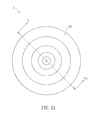
- FIG. 2A is a top view of a condensing lens according to a preferred embodiment of the present invention.
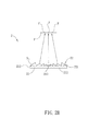
- FIG. 2B is a cross-section view of the condensing lens according to the preferred embodiment of the present invention.
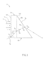
- FIG. 3 is a schematic diagram of the condensing lens according to the preferred embodiment of the present invention.
- FIG. 4 is a schematic diagram of a photovoltaic power system according to the preferred embodiment of the present invention.
- FIG. 5 is a graphic diagram showing the illuminations of the conventional condensing lens and the condensing lens according to the preferred embodiment of the present invention.
- FIG. 6 is a graphic diagram showing the concentration efficiency (tolerance) of the conventional photovoltaic power system and the photovoltaic power system according to the preferred embodiment of the present invention
- FIG. 7 is a schematic diagram showing another photovoltaic power system according to the preferred embodiment of the present invention.
- FIG. 8 is a schematic diagram showing another photovoltaic power system according to the preferred embodiment of the present invention.
- FIG 2A is a top view of a condensing lens 2 according to a preferred embodiment of the present invention
- FIG 2B is a cross-section view along line C 1 -C 2 of FIG. 2B
- the condensing lens 2 includes a lens body 21 and a prism structure 22.
- the lens body 21 has a first surface 211 and a second surface 212 opposite to each other.
- the first surface 211 is a planar surface and is used for receiving the light emitted from external light sources (e.g. solar light).
- the material of the lens body 21 includes a transparent material such as glass or transparent polymers.
- the transparent polymers are, for example, PMMA (polymethly methacrylate), PS (polystyrene), MS (methyl-methacrylate styrene), or PC (polycarbonate).
- the prism structure 22 is disposed on the second surface 212 of the lens body 21, and has a plurality of annular prism units 221.
- the annular prism units 221 are disposed on the second surface 212.
- the prism structure 22 has at least two focuses F in accordance with the annular prism units 221, and the focuses F are distributed on a plane P which is parallel to the first surface 211 of the lens body 21.
- the prism structure 22 of this embodiment includes, for example but not limited to, five annular prism units 221.
- the material of the prism structure 22 includes a transparent material such as glass or transparent polymers.
- the transparent polymers are, for example, PMMA (polymethly methacrylate), PS (polystyrene), MS (methyl-methacrylate styrene), or PC (polycarbonate).
- the material(s) of the lens body 21 and the prism structure 22 can be optionally selected from the same or different materials depending on the requirements or designs of the products.
- the lens body 21 and the prism structure 22 can be integrally formed as one piece or bonded by an adhering layer (not shown).
- the annular prism unit 221 has a cross-section of a right triangle, and the annular surface S 2 of each annular prism unit 221 is the longest side of this right triangle.
- the length of the longest side of the right triangle in the annular prism unit 221 closer to the center point 213 of the lens body 21 is shorter.
- the annular prism unit 221 of the condensing lens 2 will be further described with reference to FIG 3 .
- the first surface 211 of the lens body 21 receives a plurality of light beams L, which may include the parallel light beams L 1 and non-parallel light beams L 2 .
- the materials of the lens body 21 and the lens structure 22 are different, and only the non-parallel light beams L 2 are discussed.
- the non-parallel light beams L 2 are inputted from an incident point X 1 of the first surface 211.
- the non-parallel light beams L 2 travel to the interface between the second surface 212 and the prism structure 22, which are made of different materials, the refraction of the non-parallel light beams L 2 occurs. Accordingly, the non-parallel light beam L 2 enters the annular prism unit 221 at the incident point X 2 with an incident angle A 1 and passes through the interface with an output angle A 2 . After that, the non-parallel light beams L 2 continuously travel to the annular surface S 2 and enters an external medium at an incident point X 3 with an incident angle A 3 .
- the non-parallel light beams L 2 can be outputted from the annular surface S 2 of the annular prism unit 221 with an output angle A 4 , and then concentrated at the focuses F.
- the non-parallel light beams L 2 can have many times of refraction while passing through the annular prism unit 221 of the prism structure 22, thereby achieving the desired concentration effect.
- c represents the included angle
- r represents a distance from the annular prism unit 221 to a center point 213 of the lens body 21
- n represents a refraction index of the annular prism unit 221
- D represents a focus length of the annular prism unit 221.
- each annular prism unit 221 of the condensing lens 2 can correspond to at least one focus F, and the focuses F corresponding to the annular prism units 221 can be distributed within a certain range on the plane P.
- the focuses F can be the dots formed within a ring belt on the plane P.
- the condensing lens 2 can shift the angles of the light beams from the external light source (solar light), and remain the multiple focuses F within an extremely small range on the plane P.
- FIG. 4 is a schematic diagram of a photovoltaic power system 4 according to the preferred embodiment of the present invention.
- the photovoltaic power system 4 includes a condensing lens 2 and a photovoltaic chip 3. Since the structure and optical features of the condensing lens 2 are described in the above paragraphs, the detailed description thereof will be omitted.
- the photovoltaic chip 3 is disposed at one side of the condensing lens 2 facing the prism structure 22.
- the photovoltaic chip 3 can receive the light beams outputted from the annular prism units 221 of the prism structure 22 and perform the photoelectric conversion.
- the photovoltaic chip 3 can be a monocrystalline silicon solar cell, a polycrystalline silicon solar cell, an amorphous silicon solar cell, a compound solar cell, or an organic semiconductor solar cell.
- the focuses F corresponding to the annular prism units 221 of the prism structure 22 can be distributed on the surface of the photovoltaic chip 3. Since the annular prism units 221 of the condensing lens 2 can concentrate the light beams emitted from the external light source at multiple focuses on a plane, the present invention can still allow the focuses F to locate on the surface of the photovoltaic chip 3 even when the solar light is shifted, thereby remaining the photoelectric conversion at high efficiency.
- the condensing lens 2 when applied to the photovoltaic power system 4, the shift of the solar light is concerned. Accordingly, the positions of the annular prism units 221 on the second surface 212 of the lens body 21 can adjusted based on the shift situation of the solar light. In other words, with respect to multiple focuses F, the annular prism units 221 may not concentric circles.
- FIG 5 is a graphic diagram showing the illuminations of the conventional condensing lens 11 with different numbers of annular protruding structures 113 and the condensing lens 2 with different numbers of annular prism units 221 of the present invention.
- the illumination of the conventional condensing lens 11 is about 0.708 W/mm 2
- the illumination of the condensing lens 2 is about 0.893 W/mm 2 .
- the illumination of the conventional condensing lens 11 decreases as the number of the annular protruding structures 113 increases.
- the illumination of the condensing lens 2 of the present invention increases as the number of the annular prism units 221 increases.
- FIG 6 is a graphic diagram showing the concentration efficiency (tolerance) of the conventional photovoltaic power system 1 and the photovoltaic power system 4 of the present invention. Please refer to FIG 6 in view of the following table.
- the ratio of the output power of the photovoltaic power system 1 as the Time is 150 seconds, which means the shifted angle of the solar light after 150 seconds, to that without shift is 43%, and the ratio of the output power of the photovoltaic power system 4 as the Time is 150 seconds to that without shift is 53%. Consequently, the photovoltaic power system 4 configured with the condensing lens 2 can provide better concentration efficiency.
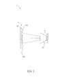
- FIG. 7 is a schematic diagram showing another photovoltaic power system 5 according to the preferred embodiment of the present invention.
- the difference between the photovoltaic power systems 4 and 5 is in that the photovoltaic power system 5 further includes a light collecting device 51.
- the light collecting device 51 is disposed between the condensing lens 2 and the photovoltaic chip 3 for receiving light beams outputted from an annular surface S 2 of each annular prism unit 221.
- the light collecting device 51 is a concentrator for collecting the light beams outputted from the annular prism units 221 and allowing the light beams to precisely focus on the photovoltaic chip 3.
- FIG. 8 is a schematic diagram showing another photovoltaic power system 6 according to the preferred embodiment of the present invention.
- the difference between the photovoltaic power systems 4 and 6 is in that the photovoltaic power system 6 further includes a heat-dissipating device 61.
- the heat-dissipating device 61 is disposed at another side of the photovoltaic chip 3 away from the prism structure 22 for dissipating the heat generated by the photovoltaic chip 3.
- the heat-dissipating device 61 can be a heat sink made of metal materials, or a complex heat sink composed of metal particles and graphite particles.
- the photovoltaic power systems 4 can further configured with both the light collecting device 51 and the heat-dissipating device 61 for improving the focus accuracy as well as the heat dissipation efficiency.
- the condensing lens and photovoltaic power system of the present invention have a prism structure with a plurality of annular prism units.
- the prism structure has at least two focuses in accordance with the annular prism units, and the focuses are distributed on a plane parallel to the first surface of the lens body. Accordingly, the illumination and concentration efficiency can be increased so as to improve the photoelectric conversion efficiency
Landscapes
- Photovoltaic Devices (AREA)
- Optical Elements Other Than Lenses (AREA)
Applications Claiming Priority (1)
| Application Number | Priority Date | Filing Date | Title |
|---|---|---|---|
| TW100140440A TW201320363A (zh) | 2011-11-04 | 2011-11-04 | 聚光透鏡及太陽能發電系統 |
Publications (2)
| Publication Number | Publication Date |
|---|---|
| EP2590231A2 true EP2590231A2 (de) | 2013-05-08 |
| EP2590231A3 EP2590231A3 (de) | 2014-05-07 |
Family
ID=45442966
Family Applications (1)
| Application Number | Title | Priority Date | Filing Date |
|---|---|---|---|
| EP11195216.4A Withdrawn EP2590231A3 (de) | 2011-11-04 | 2011-12-22 | Kondensorlinse und Photovoltaikssystem damit |
Country Status (3)
| Country | Link |
|---|---|
| US (1) | US20130112238A1 (de) |
| EP (1) | EP2590231A3 (de) |
| TW (1) | TW201320363A (de) |
Families Citing this family (3)
| Publication number | Priority date | Publication date | Assignee | Title |
|---|---|---|---|---|
| CN106680916A (zh) * | 2016-12-02 | 2017-05-17 | 乐视控股(北京)有限公司 | 一种复合棱镜片、背光模组和显示终端 |
| CN114001319B (zh) * | 2020-07-28 | 2025-05-13 | 东莞雷笛克光学有限公司 | 具有双光源的光导系统 |
| CN116015201A (zh) * | 2023-01-18 | 2023-04-25 | 昆明民策环境科技有限公司 | 中空圆环状凸透镜聚光于光伏管的发电装置 |
Family Cites Families (5)
| Publication number | Priority date | Publication date | Assignee | Title |
|---|---|---|---|---|
| EP1835547B1 (de) * | 2004-11-01 | 2011-08-24 | Technoexan Ltd. | Fotovoltaisches modul |
| US8237044B2 (en) * | 2005-06-07 | 2012-08-07 | Sharp Kabushiki Kaisha | Concentrating solar power generation unit, concentrating solar power generation apparatus, concetrating lens, concentrating lens structure, and method of manufacturing concentrating lens structure |
| JP5128808B2 (ja) * | 2006-12-06 | 2013-01-23 | スリーエム イノベイティブ プロパティズ カンパニー | フレネルレンズ |
| US20080257408A1 (en) * | 2007-04-23 | 2008-10-23 | Atomic Energy Council - Institute Of Nuclear Energy Research | Solar light concentrator |
| CN101995593A (zh) * | 2009-08-19 | 2011-03-30 | 富士迈半导体精密工业(上海)有限公司 | 非成像聚光透镜及太阳能聚光装置 |
-
2011
- 2011-11-04 TW TW100140440A patent/TW201320363A/zh unknown
- 2011-12-22 EP EP11195216.4A patent/EP2590231A3/de not_active Withdrawn
- 2011-12-22 US US13/334,761 patent/US20130112238A1/en not_active Abandoned
Non-Patent Citations (1)
| Title |
|---|
| None |
Also Published As
| Publication number | Publication date |
|---|---|
| TW201320363A (zh) | 2013-05-16 |
| EP2590231A3 (de) | 2014-05-07 |
| US20130112238A1 (en) | 2013-05-09 |
Similar Documents
| Publication | Publication Date | Title |
|---|---|---|
| US8042975B2 (en) | Plano-fresnel LED lens and LED assembly thereof | |
| US8000018B2 (en) | Köhler concentrator | |
| US20100061105A1 (en) | Convex-fresnel led lens and led assembly thereof | |
| US20060207650A1 (en) | Multi-junction solar cells with an aplanatic imaging system and coupled non-imaging light concentrator | |
| NL1040088C2 (en) | Concentrating solar panel with diffuse light conversion. | |
| JP2006313810A (ja) | 集光型太陽光発電装置 | |
| CN102749673B (zh) | 为太阳能集中器均质化光导管的结构和方法 | |
| US20130153000A1 (en) | Multi-band light collection and energy conversion module | |
| US20090314347A1 (en) | Solar multistage concentrator, and greenhouse | |
| WO2013047424A1 (ja) | 太陽光発電装置 | |
| US8248712B2 (en) | Light ray concentration device | |
| EP2590231A2 (de) | Kondensorlinse und Photovoltaikssystem damit | |
| US20100218804A1 (en) | Method for aligning a lens array to a cell array | |
| JP2014112571A (ja) | 太陽電池モジュール、太陽光発電装置および太陽電池モジュールの設置方法 | |
| RU2436192C1 (ru) | Фотоэлектрический модуль с наноструктурным фотоэлементом | |
| CN114400265A (zh) | 用于太阳能光伏发电的光电转换装置 | |
| Wei et al. | Planar solar concentrator with a v-groove array for a side-absorption concentrated photovoltaic system | |
| US20100101640A1 (en) | Optical structure and solar cell using the same | |
| JP2008311408A (ja) | 集光型太陽電池モジュール | |
| JP2015207570A (ja) | 集光型太陽光発電装置 | |
| US20120180847A1 (en) | Method for improving solar energy condensation efficiency in solar energy condensation electric power facility | |
| KR20120133025A (ko) | 셀 균일 입사를 위한 다촛점 방식의 프레넬렌즈를 이용한 집광장치 | |
| US20110283517A1 (en) | Method for Aligning a Lens Array to a Cell Array | |
| TW201119060A (en) | Concentrated solar photovoltaic module | |
| RU2353865C1 (ru) | Линейный концентратор светового излучения |
Legal Events
| Date | Code | Title | Description |
|---|---|---|---|
| PUAI | Public reference made under article 153(3) epc to a published international application that has entered the european phase |
Free format text: ORIGINAL CODE: 0009012 |
|
| AK | Designated contracting states |
Kind code of ref document: A2 Designated state(s): AL AT BE BG CH CY CZ DE DK EE ES FI FR GB GR HR HU IE IS IT LI LT LU LV MC MK MT NL NO PL PT RO RS SE SI SK SM TR |
|
| AX | Request for extension of the european patent |
Extension state: BA ME |
|
| PUAL | Search report despatched |
Free format text: ORIGINAL CODE: 0009013 |
|
| AK | Designated contracting states |
Kind code of ref document: A3 Designated state(s): AL AT BE BG CH CY CZ DE DK EE ES FI FR GB GR HR HU IE IS IT LI LT LU LV MC MK MT NL NO PL PT RO RS SE SI SK SM TR |
|
| AX | Request for extension of the european patent |
Extension state: BA ME |
|
| RIC1 | Information provided on ipc code assigned before grant |
Ipc: H01L 31/052 20140101AFI20140328BHEP |
|
| STAA | Information on the status of an ep patent application or granted ep patent |
Free format text: STATUS: THE APPLICATION IS DEEMED TO BE WITHDRAWN |
|
| 18D | Application deemed to be withdrawn |
Effective date: 20140701 |