EP2590280A2 - Système de canal de sol pour le guidage de câble et le montage d'appareils - Google Patents
Système de canal de sol pour le guidage de câble et le montage d'appareils Download PDFInfo
- Publication number
- EP2590280A2 EP2590280A2 EP12306358.8A EP12306358A EP2590280A2 EP 2590280 A2 EP2590280 A2 EP 2590280A2 EP 12306358 A EP12306358 A EP 12306358A EP 2590280 A2 EP2590280 A2 EP 2590280A2
- Authority
- EP
- European Patent Office
- Prior art keywords
- channel
- floor
- strip
- brush
- carrier strip
- Prior art date
- Legal status (The legal status is an assumption and is not a legal conclusion. Google has not performed a legal analysis and makes no representation as to the accuracy of the status listed.)
- Granted
Links
Images


Classifications
-
- H—ELECTRICITY
- H02—GENERATION; CONVERSION OR DISTRIBUTION OF ELECTRIC POWER
- H02G—INSTALLATION OF ELECTRIC CABLES OR LINES, OR OF COMBINED OPTICAL AND ELECTRIC CABLES OR LINES
- H02G3/00—Installations of electric cables or lines or protective tubing therefor in or on buildings, equivalent structures or vehicles
- H02G3/02—Details
- H02G3/04—Protective tubing or conduits, e.g. cable ladders or cable troughs
- H02G3/0437—Channels
-
- E—FIXED CONSTRUCTIONS
- E04—BUILDING
- E04F—FINISHING WORK ON BUILDINGS, e.g. STAIRS, FLOORS
- E04F17/00—Vertical ducts; Channels, e.g. for drainage
- E04F17/08—Vertical ducts; Channels, e.g. for drainage for receiving utility lines, e.g. cables, pipes
-
- H—ELECTRICITY
- H02—GENERATION; CONVERSION OR DISTRIBUTION OF ELECTRIC POWER
- H02G—INSTALLATION OF ELECTRIC CABLES OR LINES, OR OF COMBINED OPTICAL AND ELECTRIC CABLES OR LINES
- H02G3/00—Installations of electric cables or lines or protective tubing therefor in or on buildings, equivalent structures or vehicles
- H02G3/02—Details
- H02G3/04—Protective tubing or conduits, e.g. cable ladders or cable troughs
- H02G3/0406—Details thereof
- H02G3/0418—Covers or lids; Their fastenings
-
- H—ELECTRICITY
- H02—GENERATION; CONVERSION OR DISTRIBUTION OF ELECTRIC POWER
- H02G—INSTALLATION OF ELECTRIC CABLES OR LINES, OR OF COMBINED OPTICAL AND ELECTRIC CABLES OR LINES
- H02G3/00—Installations of electric cables or lines or protective tubing therefor in or on buildings, equivalent structures or vehicles
- H02G3/02—Details
- H02G3/08—Distribution boxes; Connection or junction boxes
- H02G3/18—Distribution boxes; Connection or junction boxes providing line outlets
- H02G3/185—Floor outlets and access cups
-
- H—ELECTRICITY
- H02—GENERATION; CONVERSION OR DISTRIBUTION OF ELECTRIC POWER
- H02G—INSTALLATION OF ELECTRIC CABLES OR LINES, OR OF COMBINED OPTICAL AND ELECTRIC CABLES OR LINES
- H02G3/00—Installations of electric cables or lines or protective tubing therefor in or on buildings, equivalent structures or vehicles
- H02G3/02—Details
- H02G3/06—Joints for connecting lengths of protective tubing or channels, to each other or to casings, e.g. to distribution boxes; Ensuring electrical continuity in the joint
- H02G3/0608—Joints for connecting non cylindrical conduits, e.g. channels
Definitions
- the present invention relates to a floor duct system for wiring and equipment installation.
- Floor ducts or parapet ducts for electrical installations allow cable routing or device installation of electrical devices in the underbody, so that the duct system is invisible.
- a significant advantage of a channel system in the subfloor is that cables and boxes in the wall are no longer necessary and thus the electrical connections and lines can be moved to the place where they are needed.
- a floor duct has corresponding outlets, which are usually implemented in the form of a brush bar.
- the cables can be routed directly into the room via the brush strip on the wall side.
- Such a floor duct is for example in the DE 20 2005 018 605 U1 described.
- the channel consists of a base with U-shaped cross-section, a bottom and two side walls and at least one removable lid.
- the lid has at least one short leg, and on the side wall of the lower part a web is provided inside. The free end of the web is shaped so that the leg of the lid removably fits into the correspondingly shaped end.
- the brush strip to the cable outlet is connected to the lid.
- the flooring is placed on the lid. To adapt the brush strip to a resting on the lid flooring this is made adjustable in height.
- this channel is different in terms of wiring and equipment installation requirements not flexible enough. If the channel is guided, for example, in the middle of the room, a brush strip is dispensable. Also, the device installation is not very flexible. If the channel has to be laid around a corner, separate flat angles are required for the inside corner and the outside corner. The installer must therefore carry several accessories with it.
- Another channel system is for example in the DE 203 13 160 U1 described in which a laying in floor construction channel for wiring and equipment installation is described in which the lid has a lateral projection which overlaps the floor structure.
- a parapet channel for electrical installations with a substantially U-shaped installation channel and a cover member which is supported on the channel, preferably pivotable, is in the DE 296 06 869 U1 described. Between the cover and the installation channel is a gap to the outlet of electrical leads.
- the installation channel is arranged in a mounting target position with a substantially horizontally oriented base and vertically upwardly directed legs.
- Other parapet channels of the aforementioned type are exemplary in the EP 0 758 809 B1 and the DE 200 10 253 U1 described.
- the present invention is therefore an object of the invention to provide a floor duct system, which offers the fitter the greatest possible flexibility in its different variants and in which at the same time the assembly over known duct systems for different mounting situations is facilitated.
- the floor duct system consists of a U-shaped trunking base with side walls, a bottom and side cover retaining profiles.
- the lid holding profiles serve to support and hold the lid (top or cover).
- a removable lid covers the interior of the trunking base at least partially or completely depending on the mounting situation.
- To support the upper part and possibly for attachment of electrical installation devices located at the bottom of the trunking base a releasably secured and displaceable system tray bar. This replaces the conventional C-rail.
- the system carrier strip can be plugged into different positions on the trunking base. For this purpose, located on the channel bottom opposite the channel bottom projecting tabs on the system carrier strip can be fastened. With regard to the device installation, this provides the greatest possible flexibility while at the same time facilitating installation access to the devices.
- the floor channel system according to the invention further consists of at least one laterally attached to the channel inside of the side walls of the trunking base decking strip for completion of a floor covering, such as parquet, laminate, slabs or carpet.
- the lateral covering strip is arranged between the cover holding profile and the side wall of the channel lower part and can be adjusted in height relative to the side wall of the channel lower part.
- the covering strip can be adapted to the different heights of the floor covering.
- a leveling of the floor covering with the covering strip is possible, a gap formation is prevented.
- At least one sliding securing strip is attached to the underside of the lid, which is laterally supported against a cover holding profile.
- the lid is held in a fixed position, a displacement is prevented.
- the sliding safety strip also ensures a grounding function to enable equipotential bonding between the trunking base and the cover.
- an outlet brush is provided which can be fastened by means of a specially provided brush carrier strip in different positions on the trunking base.
- the floor channel system according to the invention can thereby be used in various assembly situations and implemented in various design variants.
- the covering strip is preferably arranged to the space side at the channel lower part, while the outlet brush is held to the wall side by a brush carrier strip connected to the channel lower part.
- the brush carrier strip is designed with the outlet brush against the side wall of the trunking base height adjustable. Opposite the brush carrier strip runs parallel height adjustable stop bar, which is arranged between the lid and the outlet brush.
- the covering strip, the brush holder strip and / or the stop strip are made height-adjustable by means of elongated holes incorporated therein for positioning and subsequent screwing.
- the slots allow a stepless height positioning of the individual strips and adaptation to the floor covering.
- the floor duct is provided with a display means, for example a ribbon, a lighting means or a light cord, in particular an LED lighting.
- a display means for example a ribbon, a lighting means or a light cord, in particular an LED lighting.
- an elongated chamber for receiving the display means is formed on the brush carrier strip.
- a strip-shaped, continuous or punctual illumination along the channel can take place.
- a lighting is parallel to the outlet brush.
- the foot end of the outlet brush is preferably held by the brush carrier strip by means of a U-shaped clamping profile.
- the system tray bar is displaceable in different positions.
- the channel system is covered with a continuous lid.
- no outlet brush is provided. This is used, for example, when laying the lines in the middle of the room.
- the continuous cover is replaced by a slightly smaller cover with an additional outlet brush, which is connected in height adjustable manner in accordance with the invention via the brush carrier strip with the channel lower part.
- the system carrier strip is mounted on the wall side so that sufficient space is available for device installation. At the same time, the installer has easier access for the installation of the Elektroninstallationstechnik and their connections.
- the brush carrier strip is to be additionally equipped with a display means, for example an LED illumination
- a brush carrier strip is provided for this purpose, which is equipped with an additional chamber for guiding the display means.
- the outlet brush will need to be further offset to the center of the channel.
- it is offset further inwards via the tabs formed on the bottom of the channel lower part. As a result, the distance between the system carrier strip and the inner wall of the side wall of the channel lower part is increased.
- the three variants allow the greatest possible flexibility with few components during assembly.
- the system carrier strip is preferably clamped under opposite the bottom of the channel bottom slightly protruding tabs, which are formed at the bottom of the channel bottom. From these tabs, the system tray bar is held. To introduce the tabs recesses are preferably provided on the foot of the system tray bar.
- a coupling element is preferably provided, which can be attached to it via tabs formed on the bottom at the end of the trunking base.
- the coupling element has on at least one side a side wall with a slot mounted therein. Thereby, the coupling element can be plugged in different positions and then bolted to the trunking base.
- the end of the channel system forms an end plate, which can be attached via tabs formed thereon to the bottom at the end of the channel lower part.
- the end plate is adaptable to the floor covering via a height-adjustable covering edge. Again, the height positioning is done via a slot.
- a low angle is provided, which can be used both as an inner corner and as an outer corner. So far, different flat angles were required for this purpose.
- An internal and external corner mounting is made possible by the fact that the system tray bar can be plugged into different positions on both sides via tabs formed on the bottom of the trunking base. The installer can thus use a flat angle either for êteck- or thorougheckmontage during installation.
- the floor duct system according to the invention is characterized in that in addition to the floor duct and a baseboard is mounted. This is made possible by the adjustable brush in different positions. As a result, even when attaching a baseboard in the underbody area cables from the channel interior to the outside or vice versa are performed.
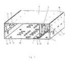
- a first embodiment of the floor duct system according to the invention is shown.
- the lower channel part 1 consists of a bottom 28 and two lateral side walls 27, which give the channel lower part 1 a U-shape.
- a system carrier strip 7 is arranged at the bottom 28 of the channel base 1.
- the system carrier strip 7 serves to support the lid 6.
- the system carrier bar 7 can be set in different positions and is held on the base 28 formed tabs 9.
- the tabs 9 are guided at the bottom of the channel bottom part 1.
- For leveling the floor channel in the subsoil leveling screws are provided, which can be screwed through corresponding threaded openings 12.
- a lid 6 On the channel lower part, a lid 6 is placed. This is held by cover holding profiles 11 and clamped on a sliding securing strip 8, which is supported against the lid holding profiles 11. There is an electrical contact between the cover holding profiles 11 and the sliding securing strip 8 Potential equalization, so that the sliding securing strip 8 at the same time has a grounding function.
- different floor coverings can be applied, such as laminate, parquet, slabs, carpeting.
- side covering strips 10 are provided, which are arranged laterally on the channel inside a side wall 27 of the channel bottom part 1.
- the covering strip 10 is guided upwards along the side wall 27 of the channel lower part 1.
- a slot 15 for attachment is a slot 15, in which a screw with the side wall 27 of the channel base 1 is carried out.
- two covering strips 10 are shown on the left and right sides. The embodiment shown serves to guide the cables and lines in the channel interior and is used for wiring, for example in the center of the room.
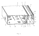
- a second embodiment in which cable passages are provided via an outlet brush 4.
- the outlet brush 4 is attached to a brush carrier strip 2.
- the attachment takes place via the foot end of the outlet brush 4, which is held by the brush carrier strip 2 by means of a U-shaped clamping profile 3.
- the brush carrier strip 2 is height adjustable via slots 13.
- the covering strip 10 is independently height-adjustable with respect to the brush carrier strip 2. In this way, the best possible adaptation to the respective floor covering is possible.
- the covering strip 10 can be seen on the right side to the middle of the room.
- To the wall side own stop bar 5 is provided with slots 14 which has a U-shaped leg at the top.
- the system carrier strip 7 is fastened in a first position to the bottom 28 of the channel lower part 1.
- Fig. 3 can be seen a third embodiment in which the system support bar 7 is further offset inwards to the middle of the channel. As a result, the distance between the system carrier strip 7 and side wall 27 of the channel lower part 1 is increased.
- the outlet brush 4 is also oriented further to the middle of the channel.
- the brush carrier strip 2 has an additional chamber 17, in which a display means, such as a light source, a light cord, LED lighting or a ribbon can be used.
- the foot of the outlet brush 4 is held by a U-shaped clamping profile 3.
- the outlet brush 4 is not with the lid 6 itself, but connected via the brush carrier strip 2 with the channel lower part 1 height adjustable.
- the embodiment shown also allows the attachment of a baseboard, without the cable outlet would be affected by the outlet brush 4.
- the covering strip 10, the stop strip 5 and the brush carrier strip 2 are screwed to the channel lower part 1 via corresponding elongated holes 14, 15, 13.
- corresponding notches 32 are formed on the upper side of the side wall 27 of the channel lower part 1. This allows the installer to find the bolted position more easily.
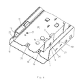
- a coupling element 18 is shown, which is provided for connecting two abutting cable duct sections.
- the coupling element 18 is connected via tabs 19 with the bottom 28 of the channel bottom part 1 and screwed through openings 20.
- a side wall 30 is provided with a slot 21.
- the system carrier strip 7 has horizontal bearing surfaces 16 for receiving the lid 6 (not shown) and recesses 29 at the foot, which serve to receive the tabs 9 formed on the bottom 28 of the channel lower part 1.
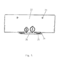
- FIG. 5 an end plate 22 is shown to the end of the channel system.
- the end plate 22 is fastened to the bottom 28 of the trunking 1 via tabs 25 formed on a doormat 24.
- a height-adjustable covering edge allows adaptation to the respective floor covering.
- a screwing takes place via a corresponding opening 23.
- openings 26 for example, for incoming pipes and lines, provided.
- a flat angle 31 is shown.
- the flat angle 31 according to the invention can be used both for installation as an inner corner and for mounting as an outer corner. This is made possible by means of the displaceable system carrier strips 7, which can be installed in different positions according to the assembly requirement.
- the floor duct system according to the invention enables the complete equipment of an office space with a floor duct via the various design variants. It is particularly advantageous that with few components a complete duct mounting is made possible and that different requirements with regard to the provision of terminals and electrical installation equipment with a single Channel system can be considered.
- a channel section will be used in which the lower channel part is completely covered with the upper part of the channel (cover). If it is necessary to provide connections for electrical installation devices, then the assembly takes place with an outlet brush strip which, if required, can be displaced in accordance with the requirement for the channel center via the brush support strip according to the invention.
- Height-adjustable covering strips, stop strips, brush carrier strips allow optimal leveling to the particular floor covering used. The device installation and the device access are also considerably facilitated by displaceable system carrier strips.
Landscapes
- Engineering & Computer Science (AREA)
- Architecture (AREA)
- Civil Engineering (AREA)
- Structural Engineering (AREA)
- Details Of Indoor Wiring (AREA)
- Installation Of Indoor Wiring (AREA)
Priority Applications (1)
| Application Number | Priority Date | Filing Date | Title |
|---|---|---|---|
| PL12306358T PL2590280T3 (pl) | 2011-11-02 | 2012-10-31 | System kanałów podłogowych do prowadzenia przewodów i wbudowywania urządzeń |
Applications Claiming Priority (1)
| Application Number | Priority Date | Filing Date | Title |
|---|---|---|---|
| DE202011107398U DE202011107398U1 (de) | 2011-11-02 | 2011-11-02 | Bodenkanalsystem zur Leitungsführung und zum Geräteeinbau |
Publications (3)
| Publication Number | Publication Date |
|---|---|
| EP2590280A2 true EP2590280A2 (fr) | 2013-05-08 |
| EP2590280A3 EP2590280A3 (fr) | 2016-01-06 |
| EP2590280B1 EP2590280B1 (fr) | 2018-06-27 |
Family
ID=47429692
Family Applications (1)
| Application Number | Title | Priority Date | Filing Date |
|---|---|---|---|
| EP12306358.8A Active EP2590280B1 (fr) | 2011-11-02 | 2012-10-31 | Système de canal de sol pour le guidage de câble et le montage d'appareils |
Country Status (3)
| Country | Link |
|---|---|
| EP (1) | EP2590280B1 (fr) |
| DE (1) | DE202011107398U1 (fr) |
| PL (1) | PL2590280T3 (fr) |
Families Citing this family (4)
| Publication number | Priority date | Publication date | Assignee | Title |
|---|---|---|---|---|
| CN107154603A (zh) * | 2017-07-16 | 2017-09-12 | 镇江市神龙电器管件有限公司 | 一种散热性能好的铝合金桥架 |
| PL3723215T3 (pl) * | 2017-09-29 | 2022-10-10 | Tehalit Gmbh | Ustawiana krawędź stykowa okładziny do kanałów kablowych |
| GB2606413B (en) * | 2021-06-03 | 2023-05-31 | Oxford Direct Services Trading Ltd | Cable channel |
| DE102021132935A1 (de) | 2021-12-14 | 2023-06-15 | Tehalit Gmbh | Bodenkanal mit schwenkbarer Abdeckung |
Citations (5)
| Publication number | Priority date | Publication date | Assignee | Title |
|---|---|---|---|---|
| DE29606869U1 (de) | 1996-04-16 | 1996-07-11 | OBO Bettermann GmbH & Co. KG, 58710 Menden | Brüstungskanal für elektrotechnische Installationen |
| DE20010253U1 (de) | 2000-01-12 | 2000-08-24 | OBO Bettermann GmbH & Co. KG, 58710 Menden | Kabelkanal |
| EP0758809B1 (fr) | 1995-08-10 | 2002-01-16 | Tehalit GmbH & Co. KG | Canalisation de paroi pour installation électrique |
| DE20313160U1 (de) | 2003-08-26 | 2005-01-05 | Tehalit Gmbh & Co. Kg | Im Bodenaufbau verlegbarer Kanal |
| DE202005018605U1 (de) | 2005-08-03 | 2006-12-14 | Tehalit Gmbh | Kanal für Leitungsführung und Geräteeinbau |
Family Cites Families (4)
| Publication number | Priority date | Publication date | Assignee | Title |
|---|---|---|---|---|
| DE6602215U (de) * | 1969-01-16 | 1969-05-08 | Wiser & Anliker Fa | Bruestungskanal-profil, insbesondere aus stranggepresstem aluminium |
| DE9003119U1 (de) * | 1990-03-16 | 1990-05-17 | Grad, Kurt, 8196 Eurasburg | Installationskanalanordnung |
| DE19848525C2 (de) * | 1998-10-21 | 2001-07-26 | Lampertz Fab Org | Bausatz für Kabelkanäle eines Arbeitsplatz-Möbels |
| DE20113696U1 (de) * | 2001-08-18 | 2003-01-09 | Tehalit GmbH & Co. KG, 67716 Heltersberg | Installationskanal |
-
2011
- 2011-11-02 DE DE202011107398U patent/DE202011107398U1/de not_active Expired - Lifetime
-
2012
- 2012-10-31 PL PL12306358T patent/PL2590280T3/pl unknown
- 2012-10-31 EP EP12306358.8A patent/EP2590280B1/fr active Active
Patent Citations (5)
| Publication number | Priority date | Publication date | Assignee | Title |
|---|---|---|---|---|
| EP0758809B1 (fr) | 1995-08-10 | 2002-01-16 | Tehalit GmbH & Co. KG | Canalisation de paroi pour installation électrique |
| DE29606869U1 (de) | 1996-04-16 | 1996-07-11 | OBO Bettermann GmbH & Co. KG, 58710 Menden | Brüstungskanal für elektrotechnische Installationen |
| DE20010253U1 (de) | 2000-01-12 | 2000-08-24 | OBO Bettermann GmbH & Co. KG, 58710 Menden | Kabelkanal |
| DE20313160U1 (de) | 2003-08-26 | 2005-01-05 | Tehalit Gmbh & Co. Kg | Im Bodenaufbau verlegbarer Kanal |
| DE202005018605U1 (de) | 2005-08-03 | 2006-12-14 | Tehalit Gmbh | Kanal für Leitungsführung und Geräteeinbau |
Also Published As
| Publication number | Publication date |
|---|---|
| EP2590280A3 (fr) | 2016-01-06 |
| EP2590280B1 (fr) | 2018-06-27 |
| DE202011107398U1 (de) | 2013-02-04 |
| PL2590280T3 (pl) | 2018-11-30 |
Similar Documents
| Publication | Publication Date | Title |
|---|---|---|
| DE69117294T2 (de) | Regelbare platte- und befestigungseinrichtung | |
| EP2590280B1 (fr) | Système de canal de sol pour le guidage de câble et le montage d'appareils | |
| DE19723558A1 (de) | Sockelleiste mit Sockelclips | |
| EP2045891B1 (fr) | Installation d'un canal de paroi doté d'un chemin de câbles installé dans la pierre taillée pour pièces intérieures d'immeuble | |
| EP2445069A1 (fr) | Système de profilé d'angle | |
| EP0305338B1 (fr) | Ensemble de pièces et son utilisation pour la construction de conduits et de boîtiers dans un immeuble | |
| DE19534458A1 (de) | Raum-Installationssystem | |
| EP1912302A2 (fr) | Dispositif de liaison de postes de travail dans un réseau d'énergie, de données et/ou de communication ainsi que canal de montage et de support pour un tel dispositif | |
| EP1443617B1 (fr) | Ensemble rail de support pour armoires électriques | |
| EP3462557B1 (fr) | Arête de jonction formant revêtement réglable pour gouttière de câble | |
| EP2872712B1 (fr) | Kit de construction destiné à la réalisation de revêtements | |
| EP1750340B1 (fr) | caniveau destiné à loger des câbles et des appareils | |
| DE2852483A1 (de) | Sockelleistenkanal fuer elektroinstallationen | |
| EP3217495A1 (fr) | Goulotte electrique | |
| AT513448B1 (de) | Energieplatte | |
| DE102014001411B4 (de) | lsolierende Schutzplatte | |
| DE202005017279U1 (de) | Unterflur-Kabelkanalsystem | |
| CH696309A5 (de) | Luftauslass. | |
| DE202022104859U1 (de) | Kanalanordnung mit einem Leitungsführungskanal und einem Geräteträger | |
| WO2009018869A1 (fr) | Ensemble de latte de séparation | |
| DE29521454U1 (de) | Raum-Installationssystem | |
| EP1511145A2 (fr) | Canalisation pour installation dans une structure de sol | |
| DE102015014712A1 (de) | Wand -und systemkomponententragendes Elektrifizierungssystem mit integrierter Schnellmontagefunktion von elektrischen Systemkomponenten | |
| EP4009459A1 (fr) | Boîte d'installation pour murs creux | |
| DE2407180A1 (de) | Kabelkanal fuer elektrische installationen |
Legal Events
| Date | Code | Title | Description |
|---|---|---|---|
| PUAI | Public reference made under article 153(3) epc to a published international application that has entered the european phase |
Free format text: ORIGINAL CODE: 0009012 |
|
| AK | Designated contracting states |
Kind code of ref document: A2 Designated state(s): AL AT BE BG CH CY CZ DE DK EE ES FI FR GB GR HR HU IE IS IT LI LT LU LV MC MK MT NL NO PL PT RO RS SE SI SK SM TR |
|
| AX | Request for extension of the european patent |
Extension state: BA ME |
|
| PUAL | Search report despatched |
Free format text: ORIGINAL CODE: 0009013 |
|
| AK | Designated contracting states |
Kind code of ref document: A3 Designated state(s): AL AT BE BG CH CY CZ DE DK EE ES FI FR GB GR HR HU IE IS IT LI LT LU LV MC MK MT NL NO PL PT RO RS SE SI SK SM TR |
|
| AX | Request for extension of the european patent |
Extension state: BA ME |
|
| RIC1 | Information provided on ipc code assigned before grant |
Ipc: H02G 3/04 20060101AFI20151203BHEP Ipc: H02G 3/06 20060101ALN20151203BHEP Ipc: E04F 17/08 20060101ALI20151203BHEP |
|
| 17P | Request for examination filed |
Effective date: 20160701 |
|
| RBV | Designated contracting states (corrected) |
Designated state(s): AL AT BE BG CH CY CZ DE DK EE ES FI FR GB GR HR HU IE IS IT LI LT LU LV MC MK MT NL NO PL PT RO RS SE SI SK SM TR |
|
| GRAP | Despatch of communication of intention to grant a patent |
Free format text: ORIGINAL CODE: EPIDOSNIGR1 |
|
| RIC1 | Information provided on ipc code assigned before grant |
Ipc: H02G 3/06 20060101ALN20171026BHEP Ipc: H02G 3/18 20060101ALN20171026BHEP Ipc: H02G 3/04 20060101AFI20171026BHEP Ipc: E04F 17/08 20060101ALI20171026BHEP |
|
| INTG | Intention to grant announced |
Effective date: 20171115 |
|
| GRAJ | Information related to disapproval of communication of intention to grant by the applicant or resumption of examination proceedings by the epo deleted |
Free format text: ORIGINAL CODE: EPIDOSDIGR1 |
|
| GRAS | Grant fee paid |
Free format text: ORIGINAL CODE: EPIDOSNIGR3 |
|
| INTC | Intention to grant announced (deleted) | ||
| RIC1 | Information provided on ipc code assigned before grant |
Ipc: E04F 17/08 20060101ALI20180312BHEP Ipc: H02G 3/04 20060101AFI20180312BHEP Ipc: H02G 3/18 20060101ALN20180312BHEP Ipc: H02G 3/06 20060101ALN20180312BHEP |
|
| GRAP | Despatch of communication of intention to grant a patent |
Free format text: ORIGINAL CODE: EPIDOSNIGR1 |
|
| INTG | Intention to grant announced |
Effective date: 20180423 |
|
| GRAA | (expected) grant |
Free format text: ORIGINAL CODE: 0009210 |
|
| AK | Designated contracting states |
Kind code of ref document: B1 Designated state(s): AL AT BE BG CH CY CZ DE DK EE ES FI FR GB GR HR HU IE IS IT LI LT LU LV MC MK MT NL NO PL PT RO RS SE SI SK SM TR |
|
| REG | Reference to a national code |
Ref country code: GB Ref legal event code: FG4D Free format text: NOT ENGLISH |
|
| REG | Reference to a national code |
Ref country code: AT Ref legal event code: REF Ref document number: 1013136 Country of ref document: AT Kind code of ref document: T Effective date: 20180715 |
|
| REG | Reference to a national code |
Ref country code: IE Ref legal event code: FG4D Free format text: LANGUAGE OF EP DOCUMENT: GERMAN |
|
| REG | Reference to a national code |
Ref country code: DE Ref legal event code: R096 Ref document number: 502012012933 Country of ref document: DE |
|
| REG | Reference to a national code |
Ref country code: CH Ref legal event code: NV Representative=s name: RENTSCH PARTNER AG, CH |
|
| REG | Reference to a national code |
Ref country code: FR Ref legal event code: PLFP Year of fee payment: 7 |
|
| PG25 | Lapsed in a contracting state [announced via postgrant information from national office to epo] |
Ref country code: SE Free format text: LAPSE BECAUSE OF FAILURE TO SUBMIT A TRANSLATION OF THE DESCRIPTION OR TO PAY THE FEE WITHIN THE PRESCRIBED TIME-LIMIT Effective date: 20180627 Ref country code: LT Free format text: LAPSE BECAUSE OF FAILURE TO SUBMIT A TRANSLATION OF THE DESCRIPTION OR TO PAY THE FEE WITHIN THE PRESCRIBED TIME-LIMIT Effective date: 20180627 Ref country code: NO Free format text: LAPSE BECAUSE OF FAILURE TO SUBMIT A TRANSLATION OF THE DESCRIPTION OR TO PAY THE FEE WITHIN THE PRESCRIBED TIME-LIMIT Effective date: 20180927 Ref country code: BG Free format text: LAPSE BECAUSE OF FAILURE TO SUBMIT A TRANSLATION OF THE DESCRIPTION OR TO PAY THE FEE WITHIN THE PRESCRIBED TIME-LIMIT Effective date: 20180927 Ref country code: FI Free format text: LAPSE BECAUSE OF FAILURE TO SUBMIT A TRANSLATION OF THE DESCRIPTION OR TO PAY THE FEE WITHIN THE PRESCRIBED TIME-LIMIT Effective date: 20180627 |
|
| REG | Reference to a national code |
Ref country code: NL Ref legal event code: MP Effective date: 20180627 |
|
| REG | Reference to a national code |
Ref country code: LT Ref legal event code: MG4D |
|
| PG25 | Lapsed in a contracting state [announced via postgrant information from national office to epo] |
Ref country code: RS Free format text: LAPSE BECAUSE OF FAILURE TO SUBMIT A TRANSLATION OF THE DESCRIPTION OR TO PAY THE FEE WITHIN THE PRESCRIBED TIME-LIMIT Effective date: 20180627 Ref country code: HR Free format text: LAPSE BECAUSE OF FAILURE TO SUBMIT A TRANSLATION OF THE DESCRIPTION OR TO PAY THE FEE WITHIN THE PRESCRIBED TIME-LIMIT Effective date: 20180627 Ref country code: GR Free format text: LAPSE BECAUSE OF FAILURE TO SUBMIT A TRANSLATION OF THE DESCRIPTION OR TO PAY THE FEE WITHIN THE PRESCRIBED TIME-LIMIT Effective date: 20180928 Ref country code: LV Free format text: LAPSE BECAUSE OF FAILURE TO SUBMIT A TRANSLATION OF THE DESCRIPTION OR TO PAY THE FEE WITHIN THE PRESCRIBED TIME-LIMIT Effective date: 20180627 |
|
| PG25 | Lapsed in a contracting state [announced via postgrant information from national office to epo] |
Ref country code: NL Free format text: LAPSE BECAUSE OF FAILURE TO SUBMIT A TRANSLATION OF THE DESCRIPTION OR TO PAY THE FEE WITHIN THE PRESCRIBED TIME-LIMIT Effective date: 20180627 |
|
| PG25 | Lapsed in a contracting state [announced via postgrant information from national office to epo] |
Ref country code: IS Free format text: LAPSE BECAUSE OF FAILURE TO SUBMIT A TRANSLATION OF THE DESCRIPTION OR TO PAY THE FEE WITHIN THE PRESCRIBED TIME-LIMIT Effective date: 20181027 Ref country code: EE Free format text: LAPSE BECAUSE OF FAILURE TO SUBMIT A TRANSLATION OF THE DESCRIPTION OR TO PAY THE FEE WITHIN THE PRESCRIBED TIME-LIMIT Effective date: 20180627 Ref country code: SK Free format text: LAPSE BECAUSE OF FAILURE TO SUBMIT A TRANSLATION OF THE DESCRIPTION OR TO PAY THE FEE WITHIN THE PRESCRIBED TIME-LIMIT Effective date: 20180627 Ref country code: RO Free format text: LAPSE BECAUSE OF FAILURE TO SUBMIT A TRANSLATION OF THE DESCRIPTION OR TO PAY THE FEE WITHIN THE PRESCRIBED TIME-LIMIT Effective date: 20180627 Ref country code: CZ Free format text: LAPSE BECAUSE OF FAILURE TO SUBMIT A TRANSLATION OF THE DESCRIPTION OR TO PAY THE FEE WITHIN THE PRESCRIBED TIME-LIMIT Effective date: 20180627 |
|
| PG25 | Lapsed in a contracting state [announced via postgrant information from national office to epo] |
Ref country code: ES Free format text: LAPSE BECAUSE OF FAILURE TO SUBMIT A TRANSLATION OF THE DESCRIPTION OR TO PAY THE FEE WITHIN THE PRESCRIBED TIME-LIMIT Effective date: 20180627 Ref country code: SM Free format text: LAPSE BECAUSE OF FAILURE TO SUBMIT A TRANSLATION OF THE DESCRIPTION OR TO PAY THE FEE WITHIN THE PRESCRIBED TIME-LIMIT Effective date: 20180627 Ref country code: IT Free format text: LAPSE BECAUSE OF FAILURE TO SUBMIT A TRANSLATION OF THE DESCRIPTION OR TO PAY THE FEE WITHIN THE PRESCRIBED TIME-LIMIT Effective date: 20180627 |
|
| REG | Reference to a national code |
Ref country code: DE Ref legal event code: R097 Ref document number: 502012012933 Country of ref document: DE |
|
| PLBE | No opposition filed within time limit |
Free format text: ORIGINAL CODE: 0009261 |
|
| STAA | Information on the status of an ep patent application or granted ep patent |
Free format text: STATUS: NO OPPOSITION FILED WITHIN TIME LIMIT |
|
| PG25 | Lapsed in a contracting state [announced via postgrant information from national office to epo] |
Ref country code: DK Free format text: LAPSE BECAUSE OF FAILURE TO SUBMIT A TRANSLATION OF THE DESCRIPTION OR TO PAY THE FEE WITHIN THE PRESCRIBED TIME-LIMIT Effective date: 20180627 |
|
| 26N | No opposition filed |
Effective date: 20190328 |
|
| GBPC | Gb: european patent ceased through non-payment of renewal fee |
Effective date: 20181031 |
|
| REG | Reference to a national code |
Ref country code: BE Ref legal event code: MM Effective date: 20181031 |
|
| PG25 | Lapsed in a contracting state [announced via postgrant information from national office to epo] |
Ref country code: LU Free format text: LAPSE BECAUSE OF NON-PAYMENT OF DUE FEES Effective date: 20181031 Ref country code: MC Free format text: LAPSE BECAUSE OF FAILURE TO SUBMIT A TRANSLATION OF THE DESCRIPTION OR TO PAY THE FEE WITHIN THE PRESCRIBED TIME-LIMIT Effective date: 20180627 |
|
| REG | Reference to a national code |
Ref country code: IE Ref legal event code: MM4A |
|
| PG25 | Lapsed in a contracting state [announced via postgrant information from national office to epo] |
Ref country code: BE Free format text: LAPSE BECAUSE OF NON-PAYMENT OF DUE FEES Effective date: 20181031 Ref country code: SI Free format text: LAPSE BECAUSE OF FAILURE TO SUBMIT A TRANSLATION OF THE DESCRIPTION OR TO PAY THE FEE WITHIN THE PRESCRIBED TIME-LIMIT Effective date: 20180627 |
|
| PG25 | Lapsed in a contracting state [announced via postgrant information from national office to epo] |
Ref country code: IE Free format text: LAPSE BECAUSE OF NON-PAYMENT OF DUE FEES Effective date: 20181031 Ref country code: GB Free format text: LAPSE BECAUSE OF NON-PAYMENT OF DUE FEES Effective date: 20181031 |
|
| PG25 | Lapsed in a contracting state [announced via postgrant information from national office to epo] |
Ref country code: AL Free format text: LAPSE BECAUSE OF FAILURE TO SUBMIT A TRANSLATION OF THE DESCRIPTION OR TO PAY THE FEE WITHIN THE PRESCRIBED TIME-LIMIT Effective date: 20180627 |
|
| PG25 | Lapsed in a contracting state [announced via postgrant information from national office to epo] |
Ref country code: MT Free format text: LAPSE BECAUSE OF FAILURE TO SUBMIT A TRANSLATION OF THE DESCRIPTION OR TO PAY THE FEE WITHIN THE PRESCRIBED TIME-LIMIT Effective date: 20180627 |
|
| PG25 | Lapsed in a contracting state [announced via postgrant information from national office to epo] |
Ref country code: TR Free format text: LAPSE BECAUSE OF FAILURE TO SUBMIT A TRANSLATION OF THE DESCRIPTION OR TO PAY THE FEE WITHIN THE PRESCRIBED TIME-LIMIT Effective date: 20180627 |
|
| PG25 | Lapsed in a contracting state [announced via postgrant information from national office to epo] |
Ref country code: PT Free format text: LAPSE BECAUSE OF FAILURE TO SUBMIT A TRANSLATION OF THE DESCRIPTION OR TO PAY THE FEE WITHIN THE PRESCRIBED TIME-LIMIT Effective date: 20180627 |
|
| PG25 | Lapsed in a contracting state [announced via postgrant information from national office to epo] |
Ref country code: CY Free format text: LAPSE BECAUSE OF FAILURE TO SUBMIT A TRANSLATION OF THE DESCRIPTION OR TO PAY THE FEE WITHIN THE PRESCRIBED TIME-LIMIT Effective date: 20180627 Ref country code: HU Free format text: LAPSE BECAUSE OF FAILURE TO SUBMIT A TRANSLATION OF THE DESCRIPTION OR TO PAY THE FEE WITHIN THE PRESCRIBED TIME-LIMIT; INVALID AB INITIO Effective date: 20121031 Ref country code: MK Free format text: LAPSE BECAUSE OF NON-PAYMENT OF DUE FEES Effective date: 20180627 |
|
| P01 | Opt-out of the competence of the unified patent court (upc) registered |
Effective date: 20230606 |
|
| REG | Reference to a national code |
Ref country code: CH Ref legal event code: U11 Free format text: ST27 STATUS EVENT CODE: U-0-0-U10-U11 (AS PROVIDED BY THE NATIONAL OFFICE) Effective date: 20251101 |
|
| PGFP | Annual fee paid to national office [announced via postgrant information from national office to epo] |
Ref country code: DE Payment date: 20251029 Year of fee payment: 14 |
|
| PGFP | Annual fee paid to national office [announced via postgrant information from national office to epo] |
Ref country code: AT Payment date: 20251029 Year of fee payment: 14 |
|
| PGFP | Annual fee paid to national office [announced via postgrant information from national office to epo] |
Ref country code: FR Payment date: 20251027 Year of fee payment: 14 |
|
| PGFP | Annual fee paid to national office [announced via postgrant information from national office to epo] |
Ref country code: CH Payment date: 20251101 Year of fee payment: 14 |
|
| PGFP | Annual fee paid to national office [announced via postgrant information from national office to epo] |
Ref country code: PL Payment date: 20251001 Year of fee payment: 14 |