EP2590282A2 - Vorrichtung für den Geräteeinbau bei Elektroinstallationen mit integrierter Haubensicherung - Google Patents
Vorrichtung für den Geräteeinbau bei Elektroinstallationen mit integrierter Haubensicherung Download PDFInfo
- Publication number
- EP2590282A2 EP2590282A2 EP20120306359 EP12306359A EP2590282A2 EP 2590282 A2 EP2590282 A2 EP 2590282A2 EP 20120306359 EP20120306359 EP 20120306359 EP 12306359 A EP12306359 A EP 12306359A EP 2590282 A2 EP2590282 A2 EP 2590282A2
- Authority
- EP
- European Patent Office
- Prior art keywords
- hood
- lifting element
- spring cam
- lifting
- locking element
- Prior art date
- Legal status (The legal status is an assumption and is not a legal conclusion. Google has not performed a legal analysis and makes no representation as to the accuracy of the status listed.)
- Granted
Links
Images

Classifications
-
- H—ELECTRICITY
- H02—GENERATION; CONVERSION OR DISTRIBUTION OF ELECTRIC POWER
- H02G—INSTALLATION OF ELECTRIC CABLES OR LINES, OR OF COMBINED OPTICAL AND ELECTRIC CABLES OR LINES
- H02G3/00—Installations of electric cables or lines or protective tubing therefor in or on buildings, equivalent structures or vehicles
- H02G3/02—Details
- H02G3/08—Distribution boxes; Connection or junction boxes
- H02G3/14—Fastening of cover or lid to box
Definitions
- the present invention relates to a device for device installation in electrical installations with an integrated hood fuse, which can be released on request via an audible sound.
- the device according to the invention is used for device installation in electrical installations.
- a device is for example in the DE 200 08 823 U1 described.
- a device installation unit for baseboard installation channels is shown, which comprises a lower part and a hood-like upper part which can be placed on the lower part.
- the device installation unit has means for releasably securing the upper part to the lower part, which can be actuated from the front.
- To attach the hood to the lower part of a slideway is formed on the inside of the upper part.
- the slideway has a slide slot which slides in a wedge-shaped unlocking carriage, the unlocking slide being operable through an opening in the front.
- At the bottom of a tongue is formed to match the slide.
- corresponding locking means are formed on the slide track and on the tongue.
- the locking means engage automatically when placing the upper part and solve when inserting the unlocking slide again.
- Another solution for connecting the hood to the lower part is in the DE 10 2004 063 442 B4 described in which the hood is connected via angle profiles with the lower part. This creates a clamp closure.
- the device according to the invention enables a secure closure of the hood with the lower part and an audible recognition when opening the closure for the purpose of removing the hood from the lower part.
- the device according to the invention consists of a known lower part, which serves to receive one or more electrical installation devices (for example sockets, network connections, etc.).
- the hood is placed on the base and covers this.
- On the housing of the hood according to the invention a displaceable in its longitudinal direction pin-like lifting element is provided.
- the lifting element corresponds to a formed on the hood strip-shaped locking element which engages in or under at least one formed on the lower part of the spring cam.
- the lifting element By the intervention of an assembly tool (eg screwdriver), the lifting element is pushed upwards, wherein the spring cam in the sliding position of the lifting element due to the lifting movement of the lifting element in connection with the locking element in the transverse direction springs and thereby securing the hood of the lower part with a audible click releases.
- an assembly tool eg screwdriver
- the lifting element is tapered at the lower end to the front by a slope.
- the lifting element When inserting the mounting tool whose end is guided under the slope, whereby the lifting element is pushed upwards. This causes the spring element to press on the spring cam, which springs back laterally (i.e., in the transverse direction) thereby releasing the remainder of the element.
- the spring cam is preferably elastic so that it can spring back to its original position.
- the spring cam is disposed within a free cut.
- the lifting element formed on the hood is arranged in a chamber formed on the lower part and presses against the latching element from below.
- the lower part preferably has an apron at the foot end, wherein the spring cam is preferably formed in the region of the skirt.
- the spring skirt can be part of the skirt wall be.
- the spring cam itself may have a nose for clamping the locking element of the hood, which rests on the locking element and provides the necessary support. When moving the lifting element, the locking element slides over the nose of the spring cam, whereby the hood is released from the lower part.
- the spring cam may be formed in an alternative embodiment, a slot for receiving the locking element.
- the locking element of the hood is strip-shaped and designed the lifting element pin-shaped.
- Fig. 1 the device according to the invention for the device installation in electrical installations is shown.
- the hood 7 is placed on the lower part 8.
- the lower part 8 has a skirt 9 for guiding lines, for example, to connect electrical installation equipment.
- a pin-shaped lifting element 4 is formed, which is arranged in a chamber 3 on the lower part 8.
- the lifting element 4 is bevelled on the underside thereof for guiding an assembly tool 1.
- the lifting element 4 corresponds to a formed on the hood 7 strip-shaped locking element 5.
- the locking element 5 is clamped under a spring cam 6, whereby the hood 7 is fixedly connected to the lower part 8.
- the closure can be released with a handle via an assembly tool 1.
- the previously securing closure which holds the hood 7 with the lower part 8, audibly released.
- the picture to the right in the FIG. 1 shows the device according to the invention again in isometric view.
- Fig. 2 the lower part 8 is shown with the skirt 9 from the front. It can be clearly seen the chamber 3, in which the lifting element 4 of the hood 7 engages.
- hood 7 (cover) is shown.
- the locking element 5 engages under the spring cam 6 of the lower part 8 and the pin-shaped locking element 4.
- the hood 7 is firmly connected to the lower part 8 and securely held.
- the advantage of the present invention is firstly that with a simple assembly tool, the hood 7 can be separated from the lower part 8. This is done by simply inserting the assembly tool in the chamber 3 of the lower part 8. Through this interaction, the spring cam 6 is pressed inwards and the locking element 5 released with an audible "click", resulting in the release of the hood 7 of the lower part 8. The hood 7 can then be easily removed, so that the electrical installation devices inside the lower part 8 are free and accessible.
Landscapes
- Engineering & Computer Science (AREA)
- Architecture (AREA)
- Civil Engineering (AREA)
- Structural Engineering (AREA)
- Casings For Electric Apparatus (AREA)
Abstract
Description
- Die vorliegende Erfindung betrifft eine Vorrichtung für den Geräteeinbau bei Elektroinstallationen mit einer integrierten Haubensicherung, die auf Wunsch über ein hörbares Geräusch freigebbar ist.
- Die erfindungsgemäße Vorrichtung dient dem Geräteeinbau bei Elektroinstallationen. Eine solche Vorrichtung ist beispielsweise in der
DE 200 08 823 U1 beschrieben. Darin wird eine Geräteeinbaueinheit für Sockelleisteninstallationskanäle gezeigt, die ein Unterteil und ein haubenartiges Oberteil, das auf das Unterteil aufsetzbar ist, umfasst. Die Geräteeinbaueinheit besitzt Einrichtungen zur lösbaren Befestigung des Oberteils am Unterteil, die von der Vorderfront aus betätigbar sind. Zur Befestigung der Haube an dem Unterteil ist an der Innenseite des Oberteils eine Gleitbahn angeformt. Die Gleitbahn besitzt einen Gleitschlitz, der in einen keilförmigen Entriegelungsschlitten gleitet, wobei der Entriegelungsschlitten durch eine Öffnung in der Vorderfront betätigbar ist. Am Unterteil ist passend zur Gleitbahn eine Zunge angeformt. Zur Verrastung sind an der Gleitbahn und an der Zunge miteinander korrespondierende Rastmittel angeformt. Die Rastmittel verrasten beim Aufsetzen des Oberteils selbsttätig und lösen sich beim Einschieben des Entriegelungsschlittens wieder. Eine andere Lösung zur Verbindung der Haube mit dem Unterteil ist in derDE 10 2004 063 442 B4 beschrieben, bei der die Haube über Winkelprofile mit dem Unterteil verbunden wird. Dadurch wird ein Klemmverschluss erzeugt. - Die beiden genannten Beispiele zur Sicherung einer Haube an dem jeweiligen Unterteil einer Geräteeinbauvorrichtung durch eine Rastverbindung oder eine Klemmverbindung sind in manchen Situationen bei einer erforderlichen Demontage schwer zu lösen oder bei deren Montage sehr aufwändig. Insbesondere das Abnehmen der Haube von dem Unterteil erweist sich bei den bekannten Lösungen als unbefriedigend.
- Es ist daher Aufgabe der vorliegenden Erfindung, eine verbesserte Vorrichtung zum Geräteeinbau bei Elektroinstallationen anzugeben, bei der die Haube von dem Unterteil mit einem einfachen Montagewerkzeug, beispielsweise einem Schraubenzieher, schnell lösbar ist.
- Diese Aufgabe wird gelöst durch eine Vorrichtung mit den Merkmalen des Anspruchs 1. Bevorzugte Ausführungsformen finden sich in den Unteransprüchen wieder.
- Die erfindungsgemäße Vorrichtung ermöglicht einen sicheren Verschluss der Haube mit dem Unterteil und eine hörbare Erkennung beim Öffnen des Verschlusses zum Zwecke des Abnehmens der Haube von dem Unterteil. Die erfindungsgemäße Vorrichtung besteht aus einem an sich bekannten Unterteil, das zur Aufnahme eines oder mehrerer Elektroinstallationsgeräte (z.B. Steckdosen, Netzwerkanschlüsse etc.) dient. Die Haube wird auf das Unterteil aufgesetzt und deckt dieses ab. An dem Gehäuse der Haube ist erfindungsgemäß ein in dessen Längsrichtung verschiebbares stiftartiges Hubelement vorgesehen. Das Hubelement korrespondiert mit einem an der Haube ausgebildeten leistenförmigen Rastelement, welches in oder unter wenigstens eine am Unterteil ausgebildete Federnocke greift. Dadurch werden die Haube und das Unterteil im Montagezustand zusammengehalten. Durch das Eingreifen eines Montagewerkzeuges (z.B. Schraubenzieher) wird das Hubelement nach oben geschoben, wobei die Federnocke in der Verschiebeposition des Hubelementes bedingt durch die Hubbewegung des mit dem Hubelement in Verbindung stehenden Rastelementes in Querrichtung federt und dadurch die Befestigung der Haube von dem Unterteil mit einem hörbaren Klick freigibt.
- Zur Einführung des Montagewerkzeuges ist vorzugsweise das Hubelement am unteren Ende nach vorne durch eine Schräge verjüngt. Beim Einführen des Montagewerkzeuges wird dessen Ende unter die Schräge geführt, wodurch das Hubelement nach oben gedrückt wird. Dies bewirkt, dass das Federelement auf die Federnocke drückt, welche seitlich (d.h. in Querrichtung) zurückfedert und dadurch das Restelement freigibt.
- Die Federnocke ist vorzugsweise elastisch, damit sie in die Ursprungsposition zurückfedern kann. Vorzugsweise ist die Federnocke innerhalb eines Freischnittes angeordnet.
- In einer bevorzugten Ausführungsform ist das an der Haube angeformte Hubelement in einer am Unterteil ausgebildeten Kammer angeordnet und drückt von unten gegen das Rastelement. Zur Kabel- und Leitungsführung besitzt das Unterteil am Fußende vorzugsweise eine Schürze, wobei die Federnocke vorzugsweise im Bereich der Schürze ausgebildet ist. Beispielsweise kann die Federnocke Teil der Schürzenwand sein. Die Federnocke selbst kann zur Verklemmung des Rastelementes der Haube eine Nase besitzen, die auf dem Rastelement aufliegt und für den erforderlichen Halt sorgt. Beim Verschieben des Hubelementes gleitet das Rastelement über die Nase der Federnocke, wodurch die Haube vom Unterteil freigegeben wird.
- In der Federnocke kann in einer alternativen Ausführungsform ein Schlitz zur Aufnahme des Rastelementes ausgebildet sein. Vorzugsweise ist das Rastelement der Haube leistenförmig und das Hubelement stiftförmig ausgestaltet.
- Die Erfindung wird in den nachfolgenden Zeichnungen näher erläutert.
- In
Fig. 1 ist die erfindungsgemäße Vorrichtung für den Geräteeinbau bei Elektroinstallationen gezeigt. Die Haube 7 ist auf dem Unterteil 8 aufgesetzt. Das Unterteil 8 besitzt eine Schürze 9 zur Führung von Leitungen, beispielsweise um Elektroinstallationsgeräte anzuschließen. Am Fußende der Haube 7 ist ein stiftförmiges Hubelement 4 ausgebildet, das in einer Kammer 3 am Unterteil 8 angeordnet ist. Das Hubelement 4 ist an dessen Unterseite zur Führung eines Montagewerkzeuges 1 abgeschrägt. Beim Einführen des Montagewerkzeuges 1 in die Kammer 3 wird die Spitze 2 des Montagewerkzeuges 1 an die Schräge geführt, wodurch beim weiteren Hineinschieben des Montagewerkzeuges 1 das Hubelement 4 bei der gezeigten Anordnung nach oben gedrückt wird. - Das Hubelement 4 korrespondiert mit einem an der Haube 7 ausgebildeten leistenförmigen Rastelement 5. Das Rastelement 5 ist unter einer Federnocke 6 verklemmt, wodurch die Haube 7 fest mit dem Unterteil 8 verbunden ist.
- In der Verschiebeposition des Hubelementes 4 gleitet das Rastelement 5 über die Federnocke 6, wodurch die Haube 7 von dem Unterteil 8 freigegeben wird. Dazu federt die Federnocke 6 leicht zurück. Die Freigabe der Haube 7 von dem Unterteil 8 ist für den Monteur in Form eines hörbaren "Klicks" wahrnehmbar. Dadurch wird dem Monteur angezeigt, dass der Verschluss zur Sicherung der Haube 7 an dem Unterteil 8 freigegeben ist und die Haube 7 von dem Unterteil 8 entnommen werden kann.
- Bei der erfindungsgemäßen Lösung ist der Verschluss mit einem Handgriff über ein Montagewerkzeug 1 lösbar. Zudem wird der zuvor sichernde Verschluss, der die Haube 7 mit dem Unterteil 8 zusammenhält, hörbar gelöst.
- Die Abbildung rechts in der
Figur 1 zeigt die erfindungsgemäße Vorrichtung nochmals in isometrischer Darstellung. - In
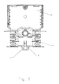
Fig. 2 ist das Unterteil 8 mit der Schürze 9 von der Vorderseite gezeigt. Man erkennt die Federnocke 6. Deutlich ist die Kammer 3 zu erkennen, in welche das Hubelement 4 der Haube 7 greift. - In
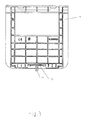
Fig. 3 ist die Haube 7 (Deckel) gezeigt. An der Unterseite der Haube 7 erkennt man das Rastelement 5, das unter die Federnocke 6 des Unterteils 8 greift und das stiftförmige Rastelement 4. Durch diese Klemmverbindung wird die Haube 7 mit dem Unterteil 8 fest verbundenen und sicher gehalten. - Der Vorteil der vorliegenden Erfindung liegt zum einen darin, dass mit einem einfachen Montagewerkzeug die Haube 7 von dem Unterteil 8 getrennt werden kann. Dies geschieht durch einfaches Einstecken des Montagewerkzeuges in die Kammer 3 des Unterteils 8. Durch diese Interaktion wird die Federnocke 6 nach innen gedrückt und das Rastelement 5 mit einem hörbaren "Klick" freigegeben, was zum Lösen der Haube 7 von dem Unterteil 8 führt. Die Haube 7 kann dann bequem abgenommen werden, so dass die Elektroinstallationsgeräte im Inneren des Unterteils 8 frei und zugänglich liegen.
Claims (9)
- Vorrichtung für den Geräteinbau bei Elektroinstallationen, bestehend aus einem Unterteil (8) zur Aufnahme eines oder mehrerer Elektroninstallationsgeräte und einer Haube (7) zum Aufsetzen auf das Unterteil (8), wobei an der Haube (7) ein in dessen Längsrichtung verschiebbares Hubelement (4) ausgebildet ist, dadurch gekennzeichnet, dass das Hubelement (4) mit einem an der Haube (7) ausgebildeten Rastelement (5) korrespondiert, welches in oder unter wenigstens eine am Unterteil (8) ausgebildete Federnocke (6) greift, wodurch die Haube (7) und das Unterteil (8) im Montagezustand zusammengehalten werden, wobei die Federnocke (6) in der Verschiebeposition des Hubelementes (4) bedingt durch die Hubbewegung des damit in Verbindung stehenden Rastelementes (5) in Querrichtung federbar ist, wodurch die Befestigung der Haube (7) von dem Unterteil (8) freigegeben wird.
- Vorrichtung nach Anspruch 1, dadurch gekennzeichnet, dass das Hubelement (4) am unteren Ende eine sich nach vorne verjüngende Schräge zur Einführung eines Montagewerkzeuges aufweist.
- Vorrichtung nach Anspruch 1 oder 2, dadurch gekennzeichnet, dass die Federnocke (6) in einem Freischnitt angeordnet ist.
- Vorrichtung nach einem der vorhergehenden Ansprüche, dadurch gekennzeichnet, dass das Hubelement (4) der Haube (7) in einer am Unterteil (8) ausgebildeten Kammer (3) angeordnet ist und von unten gegen das Rastelement (5) der Haube (7) drückt.
- Vorrichtung nach einem der vorhergehenden Ansprüche, dadurch gekennzeichnet, dass das Unterteil (8) am Fußende eine Schürze besitzt und die Federnocke (6) im Bereich der Schürze ausgebildet ist.
- Vorrichtung nach einem der vorhergehenden Ansprüche, dadurch gekennzeichnet, dass die Federnocke (6) eine Nase besitzt.
- Vorrichtung nach einem der vorhergehenden Ansprüche, dadurch gekennzeichnet, dass in der Federnocke (6) zur Aufnahme des Rastelementes (5) ein Schlitz ausgebildet ist.
- Vorrichtung nach einem der vorhergehenden Ansprüche, dadurch gekennzeichnet, dass das Rastelement (5) leistenförmig ausgestaltet ist.
- Vorrichtung nach einem der vorhergehenden Ansprüche, dadurch gekennzeichnet, dass das Hubelement (4) stiftförmig ausgestaltet ist.
Applications Claiming Priority (1)
| Application Number | Priority Date | Filing Date | Title |
|---|---|---|---|
| DE201120107455 DE202011107455U1 (de) | 2011-11-04 | 2011-11-04 | Vorrichtung für den Geräteeinbau bei Elektroinstallationen mit integrierter Haubensicherung |
Publications (3)
| Publication Number | Publication Date |
|---|---|
| EP2590282A2 true EP2590282A2 (de) | 2013-05-08 |
| EP2590282A3 EP2590282A3 (de) | 2014-03-19 |
| EP2590282B1 EP2590282B1 (de) | 2015-07-15 |
Family
ID=47294823
Family Applications (1)
| Application Number | Title | Priority Date | Filing Date |
|---|---|---|---|
| EP12306359.6A Active EP2590282B1 (de) | 2011-11-04 | 2012-10-31 | Vorrichtung für den Geräteeinbau bei Elektroinstallationen mit integrierter Haubensicherung |
Country Status (3)
| Country | Link |
|---|---|
| EP (1) | EP2590282B1 (de) |
| DE (1) | DE202011107455U1 (de) |
| ES (1) | ES2549778T3 (de) |
Citations (2)
| Publication number | Priority date | Publication date | Assignee | Title |
|---|---|---|---|---|
| DE20008823U1 (de) | 2000-05-16 | 2001-10-04 | Tehalit GmbH & Co. KG, 67716 Heltersberg | Gerätebaueinheit für Sockelleisten-Installationskanäle |
| DE102004063442B4 (de) | 2004-12-30 | 2007-07-26 | Böhrer GmbH | Pick-Up-Channel, Elektro-, Daten- und Gerätekanal |
Family Cites Families (2)
| Publication number | Priority date | Publication date | Assignee | Title |
|---|---|---|---|---|
| US5317108A (en) * | 1992-12-15 | 1994-05-31 | L.E. Mason Company | Weather-resistant electrical outlet cover assembly |
| CN102484953B (zh) * | 2009-07-28 | 2015-06-17 | 皇家飞利浦电子股份有限公司 | 带锁定结构的箱体 |
-
2011
- 2011-11-04 DE DE201120107455 patent/DE202011107455U1/de not_active Expired - Lifetime
-
2012
- 2012-10-31 EP EP12306359.6A patent/EP2590282B1/de active Active
- 2012-10-31 ES ES12306359.6T patent/ES2549778T3/es active Active
Patent Citations (2)
| Publication number | Priority date | Publication date | Assignee | Title |
|---|---|---|---|---|
| DE20008823U1 (de) | 2000-05-16 | 2001-10-04 | Tehalit GmbH & Co. KG, 67716 Heltersberg | Gerätebaueinheit für Sockelleisten-Installationskanäle |
| DE102004063442B4 (de) | 2004-12-30 | 2007-07-26 | Böhrer GmbH | Pick-Up-Channel, Elektro-, Daten- und Gerätekanal |
Also Published As
| Publication number | Publication date |
|---|---|
| EP2590282B1 (de) | 2015-07-15 |
| ES2549778T3 (es) | 2015-11-02 |
| EP2590282A3 (de) | 2014-03-19 |
| DE202011107455U1 (de) | 2013-02-05 |
Similar Documents
| Publication | Publication Date | Title |
|---|---|---|
| EP3369138B1 (de) | Kontaktierungsvorrichtung zum kontaktieren eines elektrischen leiters an eine elektrische leiterbahn | |
| DE10340571B3 (de) | Klemme zum Halten von flachen Gegenständen | |
| AT503089A2 (de) | Aufsatzteil | |
| EP3320583B1 (de) | Anschlussklemme | |
| EP2186079A1 (de) | Kennzeichnungsvorrichtung für eine elektrische leitung | |
| EP2012390B1 (de) | Erdungsklammer zum Potentialausgleich von Leitungsführungskanälen | |
| DE102009030662A1 (de) | Schraubklemmanschlussvorrichtung, insbesondere für den Anschluss eines Stromkabels an eine Stromzählerinstallation | |
| EP2590282B1 (de) | Vorrichtung für den Geräteeinbau bei Elektroinstallationen mit integrierter Haubensicherung | |
| DE10340207B4 (de) | Elektrisches Gerät mit Halte-/Lösevorrichtung | |
| EP2273640A2 (de) | Geräteträger für Sockelleistenkanäle | |
| EP1993178A2 (de) | Formteile zur Kaschierung von Schnittkanten an Kabelkanälen | |
| EP2461444B1 (de) | Schwenkbare Geräteeinbaudose für einen Kabelkanal | |
| DE202007016981U1 (de) | Befestigungsvorrichtung für ein elektrotechnisches Bauteil | |
| DE102012007298A1 (de) | Vorrichtung zum höhenverstellbaren Abhängen eines elektrischen Gerätes | |
| DE202007017167U1 (de) | Gerätehalterung zur universellen Befestigung von Installationsgeräten und Vorrichtungen an Leitungsführungskanälen | |
| DE102011054282B4 (de) | Anschlussklemme | |
| EP1420211B1 (de) | Haltevorrichtung zur Wandbefestigung eines Heizkörpers | |
| EP2367249B1 (de) | Vorrichtung zur Verschiebesicherung einer Geräteeinbaudose oder sonstigen Elektroinstallationseinrichtung an einem Leitungsführungskanal | |
| DE10205614B4 (de) | Anschlussadapter | |
| DE202011102159U1 (de) | Gerätebecher für Unterflur-Elektroinstallationen | |
| DE29611660U1 (de) | Vorrichtung zum elektrisch leitenden Verbinden einer in einem Schaltschrank eingebauten Montageplatte | |
| DE102008011217B4 (de) | Betätigungswerkzeug zum Anschließen eines isolierten Leiters | |
| DE2417802A1 (de) | Vorrichtung zum verbinden der leiter eines kabels mit starren metallkontakten einer steckdose, klemmenleiste und dgl. | |
| EP3522303A1 (de) | Anschlussblock | |
| DE29708690U1 (de) | Gehäuse, insbesondere für Verbraucherabzweigmodule |
Legal Events
| Date | Code | Title | Description |
|---|---|---|---|
| PUAI | Public reference made under article 153(3) epc to a published international application that has entered the european phase |
Free format text: ORIGINAL CODE: 0009012 |
|
| AK | Designated contracting states |
Kind code of ref document: A2 Designated state(s): AL AT BE BG CH CY CZ DE DK EE ES FI FR GB GR HR HU IE IS IT LI LT LU LV MC MK MT NL NO PL PT RO RS SE SI SK SM TR |
|
| AX | Request for extension of the european patent |
Extension state: BA ME |
|
| PUAL | Search report despatched |
Free format text: ORIGINAL CODE: 0009013 |
|
| AK | Designated contracting states |
Kind code of ref document: A3 Designated state(s): AL AT BE BG CH CY CZ DE DK EE ES FI FR GB GR HR HU IE IS IT LI LT LU LV MC MK MT NL NO PL PT RO RS SE SI SK SM TR |
|
| AX | Request for extension of the european patent |
Extension state: BA ME |
|
| RIC1 | Information provided on ipc code assigned before grant |
Ipc: H02G 3/14 20060101AFI20140212BHEP |
|
| 17P | Request for examination filed |
Effective date: 20140912 |
|
| RBV | Designated contracting states (corrected) |
Designated state(s): AL AT BE BG CH CY CZ DE DK EE ES FI FR GB GR HR HU IE IS IT LI LT LU LV MC MK MT NL NO PL PT RO RS SE SI SK SM TR |
|
| GRAP | Despatch of communication of intention to grant a patent |
Free format text: ORIGINAL CODE: EPIDOSNIGR1 |
|
| INTG | Intention to grant announced |
Effective date: 20150206 |
|
| GRAS | Grant fee paid |
Free format text: ORIGINAL CODE: EPIDOSNIGR3 |
|
| GRAA | (expected) grant |
Free format text: ORIGINAL CODE: 0009210 |
|
| AK | Designated contracting states |
Kind code of ref document: B1 Designated state(s): AL AT BE BG CH CY CZ DE DK EE ES FI FR GB GR HR HU IE IS IT LI LT LU LV MC MK MT NL NO PL PT RO RS SE SI SK SM TR |
|
| REG | Reference to a national code |
Ref country code: CH Ref legal event code: EP Ref country code: GB Ref legal event code: FG4D Free format text: NOT ENGLISH |
|
| REG | Reference to a national code |
Ref country code: IE Ref legal event code: FG4D Free format text: LANGUAGE OF EP DOCUMENT: GERMAN |
|
| REG | Reference to a national code |
Ref country code: AT Ref legal event code: REF Ref document number: 737208 Country of ref document: AT Kind code of ref document: T Effective date: 20150815 |
|
| REG | Reference to a national code |
Ref country code: DE Ref legal event code: R096 Ref document number: 502012003790 Country of ref document: DE |
|
| REG | Reference to a national code |
Ref country code: SE Ref legal event code: TRGR |
|
| REG | Reference to a national code |
Ref country code: NL Ref legal event code: FP |
|
| REG | Reference to a national code |
Ref country code: LT Ref legal event code: MG4D |
|
| PG25 | Lapsed in a contracting state [announced via postgrant information from national office to epo] |
Ref country code: NO Free format text: LAPSE BECAUSE OF FAILURE TO SUBMIT A TRANSLATION OF THE DESCRIPTION OR TO PAY THE FEE WITHIN THE PRESCRIBED TIME-LIMIT Effective date: 20151015 Ref country code: LT Free format text: LAPSE BECAUSE OF FAILURE TO SUBMIT A TRANSLATION OF THE DESCRIPTION OR TO PAY THE FEE WITHIN THE PRESCRIBED TIME-LIMIT Effective date: 20150715 Ref country code: FI Free format text: LAPSE BECAUSE OF FAILURE TO SUBMIT A TRANSLATION OF THE DESCRIPTION OR TO PAY THE FEE WITHIN THE PRESCRIBED TIME-LIMIT Effective date: 20150715 Ref country code: GR Free format text: LAPSE BECAUSE OF FAILURE TO SUBMIT A TRANSLATION OF THE DESCRIPTION OR TO PAY THE FEE WITHIN THE PRESCRIBED TIME-LIMIT Effective date: 20151016 Ref country code: LV Free format text: LAPSE BECAUSE OF FAILURE TO SUBMIT A TRANSLATION OF THE DESCRIPTION OR TO PAY THE FEE WITHIN THE PRESCRIBED TIME-LIMIT Effective date: 20150715 |
|
| PG25 | Lapsed in a contracting state [announced via postgrant information from national office to epo] |
Ref country code: HR Free format text: LAPSE BECAUSE OF FAILURE TO SUBMIT A TRANSLATION OF THE DESCRIPTION OR TO PAY THE FEE WITHIN THE PRESCRIBED TIME-LIMIT Effective date: 20150715 Ref country code: PT Free format text: LAPSE BECAUSE OF FAILURE TO SUBMIT A TRANSLATION OF THE DESCRIPTION OR TO PAY THE FEE WITHIN THE PRESCRIBED TIME-LIMIT Effective date: 20151116 Ref country code: RS Free format text: LAPSE BECAUSE OF FAILURE TO SUBMIT A TRANSLATION OF THE DESCRIPTION OR TO PAY THE FEE WITHIN THE PRESCRIBED TIME-LIMIT Effective date: 20150715 Ref country code: PL Free format text: LAPSE BECAUSE OF FAILURE TO SUBMIT A TRANSLATION OF THE DESCRIPTION OR TO PAY THE FEE WITHIN THE PRESCRIBED TIME-LIMIT Effective date: 20150715 |
|
| REG | Reference to a national code |
Ref country code: DE Ref legal event code: R097 Ref document number: 502012003790 Country of ref document: DE |
|
| PG25 | Lapsed in a contracting state [announced via postgrant information from national office to epo] |
Ref country code: DK Free format text: LAPSE BECAUSE OF FAILURE TO SUBMIT A TRANSLATION OF THE DESCRIPTION OR TO PAY THE FEE WITHIN THE PRESCRIBED TIME-LIMIT Effective date: 20150715 Ref country code: CZ Free format text: LAPSE BECAUSE OF FAILURE TO SUBMIT A TRANSLATION OF THE DESCRIPTION OR TO PAY THE FEE WITHIN THE PRESCRIBED TIME-LIMIT Effective date: 20150715 Ref country code: EE Free format text: LAPSE BECAUSE OF FAILURE TO SUBMIT A TRANSLATION OF THE DESCRIPTION OR TO PAY THE FEE WITHIN THE PRESCRIBED TIME-LIMIT Effective date: 20150715 Ref country code: SK Free format text: LAPSE BECAUSE OF FAILURE TO SUBMIT A TRANSLATION OF THE DESCRIPTION OR TO PAY THE FEE WITHIN THE PRESCRIBED TIME-LIMIT Effective date: 20150715 |
|
| PLBE | No opposition filed within time limit |
Free format text: ORIGINAL CODE: 0009261 |
|
| STAA | Information on the status of an ep patent application or granted ep patent |
Free format text: STATUS: NO OPPOSITION FILED WITHIN TIME LIMIT |
|
| PG25 | Lapsed in a contracting state [announced via postgrant information from national office to epo] |
Ref country code: RO Free format text: LAPSE BECAUSE OF FAILURE TO SUBMIT A TRANSLATION OF THE DESCRIPTION OR TO PAY THE FEE WITHIN THE PRESCRIBED TIME-LIMIT Effective date: 20150715 Ref country code: LU Free format text: LAPSE BECAUSE OF FAILURE TO SUBMIT A TRANSLATION OF THE DESCRIPTION OR TO PAY THE FEE WITHIN THE PRESCRIBED TIME-LIMIT Effective date: 20151031 |
|
| REG | Reference to a national code |
Ref country code: CH Ref legal event code: PL |
|
| 26N | No opposition filed |
Effective date: 20160418 |
|
| PG25 | Lapsed in a contracting state [announced via postgrant information from national office to epo] |
Ref country code: IS Free format text: LAPSE BECAUSE OF FAILURE TO SUBMIT A TRANSLATION OF THE DESCRIPTION OR TO PAY THE FEE WITHIN THE PRESCRIBED TIME-LIMIT Effective date: 20150715 Ref country code: MC Free format text: LAPSE BECAUSE OF FAILURE TO SUBMIT A TRANSLATION OF THE DESCRIPTION OR TO PAY THE FEE WITHIN THE PRESCRIBED TIME-LIMIT Effective date: 20150715 |
|
| REG | Reference to a national code |
Ref country code: IE Ref legal event code: MM4A |
|
| PG25 | Lapsed in a contracting state [announced via postgrant information from national office to epo] |
Ref country code: LI Free format text: LAPSE BECAUSE OF NON-PAYMENT OF DUE FEES Effective date: 20151031 Ref country code: CH Free format text: LAPSE BECAUSE OF NON-PAYMENT OF DUE FEES Effective date: 20151031 |
|
| PG25 | Lapsed in a contracting state [announced via postgrant information from national office to epo] |
Ref country code: SI Free format text: LAPSE BECAUSE OF FAILURE TO SUBMIT A TRANSLATION OF THE DESCRIPTION OR TO PAY THE FEE WITHIN THE PRESCRIBED TIME-LIMIT Effective date: 20150715 |
|
| REG | Reference to a national code |
Ref country code: FR Ref legal event code: PLFP Year of fee payment: 5 |
|
| PG25 | Lapsed in a contracting state [announced via postgrant information from national office to epo] |
Ref country code: IE Free format text: LAPSE BECAUSE OF NON-PAYMENT OF DUE FEES Effective date: 20151031 |
|
| PG25 | Lapsed in a contracting state [announced via postgrant information from national office to epo] |
Ref country code: SM Free format text: LAPSE BECAUSE OF FAILURE TO SUBMIT A TRANSLATION OF THE DESCRIPTION OR TO PAY THE FEE WITHIN THE PRESCRIBED TIME-LIMIT Effective date: 20150715 Ref country code: HU Free format text: LAPSE BECAUSE OF FAILURE TO SUBMIT A TRANSLATION OF THE DESCRIPTION OR TO PAY THE FEE WITHIN THE PRESCRIBED TIME-LIMIT; INVALID AB INITIO Effective date: 20121031 Ref country code: BG Free format text: LAPSE BECAUSE OF FAILURE TO SUBMIT A TRANSLATION OF THE DESCRIPTION OR TO PAY THE FEE WITHIN THE PRESCRIBED TIME-LIMIT Effective date: 20150715 |
|
| GBPC | Gb: european patent ceased through non-payment of renewal fee |
Effective date: 20161031 |
|
| PG25 | Lapsed in a contracting state [announced via postgrant information from national office to epo] |
Ref country code: CY Free format text: LAPSE BECAUSE OF FAILURE TO SUBMIT A TRANSLATION OF THE DESCRIPTION OR TO PAY THE FEE WITHIN THE PRESCRIBED TIME-LIMIT Effective date: 20150715 |
|
| PG25 | Lapsed in a contracting state [announced via postgrant information from national office to epo] |
Ref country code: GB Free format text: LAPSE BECAUSE OF NON-PAYMENT OF DUE FEES Effective date: 20161031 Ref country code: BE Free format text: LAPSE BECAUSE OF NON-PAYMENT OF DUE FEES Effective date: 20151031 |
|
| PG25 | Lapsed in a contracting state [announced via postgrant information from national office to epo] |
Ref country code: MT Free format text: LAPSE BECAUSE OF FAILURE TO SUBMIT A TRANSLATION OF THE DESCRIPTION OR TO PAY THE FEE WITHIN THE PRESCRIBED TIME-LIMIT Effective date: 20150715 |
|
| REG | Reference to a national code |
Ref country code: FR Ref legal event code: PLFP Year of fee payment: 6 |
|
| PG25 | Lapsed in a contracting state [announced via postgrant information from national office to epo] |
Ref country code: MK Free format text: LAPSE BECAUSE OF FAILURE TO SUBMIT A TRANSLATION OF THE DESCRIPTION OR TO PAY THE FEE WITHIN THE PRESCRIBED TIME-LIMIT Effective date: 20150715 Ref country code: TR Free format text: LAPSE BECAUSE OF FAILURE TO SUBMIT A TRANSLATION OF THE DESCRIPTION OR TO PAY THE FEE WITHIN THE PRESCRIBED TIME-LIMIT Effective date: 20150715 |
|
| REG | Reference to a national code |
Ref country code: FR Ref legal event code: PLFP Year of fee payment: 7 |
|
| PG25 | Lapsed in a contracting state [announced via postgrant information from national office to epo] |
Ref country code: AL Free format text: LAPSE BECAUSE OF FAILURE TO SUBMIT A TRANSLATION OF THE DESCRIPTION OR TO PAY THE FEE WITHIN THE PRESCRIBED TIME-LIMIT Effective date: 20150715 |
|
| REG | Reference to a national code |
Ref country code: AT Ref legal event code: MM01 Ref document number: 737208 Country of ref document: AT Kind code of ref document: T Effective date: 20171031 |
|
| PG25 | Lapsed in a contracting state [announced via postgrant information from national office to epo] |
Ref country code: AT Free format text: LAPSE BECAUSE OF NON-PAYMENT OF DUE FEES Effective date: 20171031 |
|
| P01 | Opt-out of the competence of the unified patent court (upc) registered |
Effective date: 20230606 |
|
| PGFP | Annual fee paid to national office [announced via postgrant information from national office to epo] |
Ref country code: NL Payment date: 20251026 Year of fee payment: 14 |
|
| PGFP | Annual fee paid to national office [announced via postgrant information from national office to epo] |
Ref country code: DE Payment date: 20251029 Year of fee payment: 14 |
|
| PGFP | Annual fee paid to national office [announced via postgrant information from national office to epo] |
Ref country code: IT Payment date: 20251021 Year of fee payment: 14 |
|
| PGFP | Annual fee paid to national office [announced via postgrant information from national office to epo] |
Ref country code: FR Payment date: 20251027 Year of fee payment: 14 |
|
| PGFP | Annual fee paid to national office [announced via postgrant information from national office to epo] |
Ref country code: SE Payment date: 20251027 Year of fee payment: 14 |
|
| PGFP | Annual fee paid to national office [announced via postgrant information from national office to epo] |
Ref country code: ES Payment date: 20251103 Year of fee payment: 14 |