EP2590312A1 - Convertisseur de source de tension avec topologie clampée en neutre modifiée et procédé de fonctionnement d'un tel convertisseur - Google Patents
Convertisseur de source de tension avec topologie clampée en neutre modifiée et procédé de fonctionnement d'un tel convertisseur Download PDFInfo
- Publication number
- EP2590312A1 EP2590312A1 EP11187801.3A EP11187801A EP2590312A1 EP 2590312 A1 EP2590312 A1 EP 2590312A1 EP 11187801 A EP11187801 A EP 11187801A EP 2590312 A1 EP2590312 A1 EP 2590312A1
- Authority
- EP
- European Patent Office
- Prior art keywords
- terminal
- switches
- voltage source
- npc
- series
- Prior art date
- Legal status (The legal status is an assumption and is not a legal conclusion. Google has not performed a legal analysis and makes no representation as to the accuracy of the status listed.)
- Ceased
Links
Images




Classifications
-
- H—ELECTRICITY
- H02—GENERATION; CONVERSION OR DISTRIBUTION OF ELECTRIC POWER
- H02M—APPARATUS FOR CONVERSION BETWEEN AC AND AC, BETWEEN AC AND DC, OR BETWEEN DC AND DC, AND FOR USE WITH MAINS OR SIMILAR POWER SUPPLY SYSTEMS; CONVERSION OF DC OR AC INPUT POWER INTO SURGE OUTPUT POWER; CONTROL OR REGULATION THEREOF
- H02M7/00—Conversion of AC power input into DC power output; Conversion of DC power input into AC power output
- H02M7/42—Conversion of DC power input into AC power output without possibility of reversal
- H02M7/44—Conversion of DC power input into AC power output without possibility of reversal by static converters
- H02M7/48—Conversion of DC power input into AC power output without possibility of reversal by static converters using discharge tubes with control electrode or semiconductor devices with control electrode
- H02M7/53—Conversion of DC power input into AC power output without possibility of reversal by static converters using discharge tubes with control electrode or semiconductor devices with control electrode using devices of a triode or transistor type requiring continuous application of a control signal
- H02M7/537—Conversion of DC power input into AC power output without possibility of reversal by static converters using discharge tubes with control electrode or semiconductor devices with control electrode using devices of a triode or transistor type requiring continuous application of a control signal using semiconductor devices only, e.g. single switched pulse inverters
-
- H—ELECTRICITY
- H02—GENERATION; CONVERSION OR DISTRIBUTION OF ELECTRIC POWER
- H02M—APPARATUS FOR CONVERSION BETWEEN AC AND AC, BETWEEN AC AND DC, OR BETWEEN DC AND DC, AND FOR USE WITH MAINS OR SIMILAR POWER SUPPLY SYSTEMS; CONVERSION OF DC OR AC INPUT POWER INTO SURGE OUTPUT POWER; CONTROL OR REGULATION THEREOF
- H02M7/00—Conversion of AC power input into DC power output; Conversion of DC power input into AC power output
- H02M7/42—Conversion of DC power input into AC power output without possibility of reversal
- H02M7/44—Conversion of DC power input into AC power output without possibility of reversal by static converters
- H02M7/48—Conversion of DC power input into AC power output without possibility of reversal by static converters using discharge tubes with control electrode or semiconductor devices with control electrode
- H02M7/483—Converters with outputs that each can have more than two voltages levels
- H02M7/487—Neutral point clamped inverters
-
- H—ELECTRICITY
- H02—GENERATION; CONVERSION OR DISTRIBUTION OF ELECTRIC POWER
- H02M—APPARATUS FOR CONVERSION BETWEEN AC AND AC, BETWEEN AC AND DC, OR BETWEEN DC AND DC, AND FOR USE WITH MAINS OR SIMILAR POWER SUPPLY SYSTEMS; CONVERSION OF DC OR AC INPUT POWER INTO SURGE OUTPUT POWER; CONTROL OR REGULATION THEREOF
- H02M1/00—Details of apparatus for conversion
- H02M1/0048—Circuits or arrangements for reducing losses
- H02M1/0054—Transistor switching losses
-
- H—ELECTRICITY
- H02—GENERATION; CONVERSION OR DISTRIBUTION OF ELECTRIC POWER
- H02M—APPARATUS FOR CONVERSION BETWEEN AC AND AC, BETWEEN AC AND DC, OR BETWEEN DC AND DC, AND FOR USE WITH MAINS OR SIMILAR POWER SUPPLY SYSTEMS; CONVERSION OF DC OR AC INPUT POWER INTO SURGE OUTPUT POWER; CONTROL OR REGULATION THEREOF
- H02M1/00—Details of apparatus for conversion
- H02M1/0095—Hybrid converter topologies, e.g. NPC mixed with flying capacitor, thyristor converter mixed with MMC or charge pump mixed with buck
-
- Y—GENERAL TAGGING OF NEW TECHNOLOGICAL DEVELOPMENTS; GENERAL TAGGING OF CROSS-SECTIONAL TECHNOLOGIES SPANNING OVER SEVERAL SECTIONS OF THE IPC; TECHNICAL SUBJECTS COVERED BY FORMER USPC CROSS-REFERENCE ART COLLECTIONS [XRACs] AND DIGESTS
- Y02—TECHNOLOGIES OR APPLICATIONS FOR MITIGATION OR ADAPTATION AGAINST CLIMATE CHANGE
- Y02B—CLIMATE CHANGE MITIGATION TECHNOLOGIES RELATED TO BUILDINGS, e.g. HOUSING, HOUSE APPLIANCES OR RELATED END-USER APPLICATIONS
- Y02B70/00—Technologies for an efficient end-user side electric power management and consumption
- Y02B70/10—Technologies improving the efficiency by using switched-mode power supplies [SMPS], i.e. efficient power electronics conversion e.g. power factor correction or reduction of losses in power supplies or efficient standby modes
Definitions
- the present invention relates to the technology of electronic converters. It refers to a Voltage Source Converter (VSC) with Neutral-Point-Clamped (NPC) topology according to the preamble of claim 1. It also refers to a method for operating such a converter.
- VSC Voltage Source Converter
- NPC Neutral-Point-Clamped
- VSCs 3-level Voltage Source Converters
- NPC Neutral-Point-Clamped
- the 3-level conventional NPC VSC features two additional active switches, two extra isolated gate drivers, and four diodes per phase leg.
- the 3-phase 3-level NPC VSC allows 27 switch states in the space-vector diagram, whereas the 2-level VSC allows eight switch states only (see Reference (4)).
- the clearly superior controllability of the phase currents and DC-link voltage (U DC ) are the most distinct advantages over the 2-level converter (see Reference (4)).
- 3-level conventional NPC and/or T-type NPC (see Fig. 1 (c) ) systems can achieve lower losses than 2-level converters, if the considered switching frequency is high enough (see Reference (6)).
- One substantial disadvantage of the conventional NPC and/or T-type VSCs is the commonly uneven loss distribution across the semiconductor devices and the resulting asymmetrical temperature distribution over their junctions.
- modulation schemes used to enhance the system efficiency can contribute to the uneven loss distribution, making it even worse, increasing the difference of the operating temperature of the transistors and diodes inside the power module and/or widening their thermal cycling.
- NPC power modules Due to the unequal distribution of losses and consequent mismatch of junction temperature distribution across the phase-leg's semiconductors, in the particular situation of high power converters, the usage of NPC power modules normally results in low semiconductor utilization (see Reference (4)). In this way, the usage of single semiconductor devices, rated differently, is more favourable in building the bridge-legs of the converter. NPC systems, employing single semiconductors similarly rated, usually have these devices installed in separate heat sinks, in order to achieve a good thermal decoupling of the individual components. Unfortunately, the usage of different single semiconductors and/or separate heating sinks normally results in increased cost and bulky systems.
- A-NPC Active NPC
- VSC Voltage Source Converter
- NPC Neutral-Point-Clamped
- the first and second two-switch series connections each comprise two active switches in series connection
- the switchable connections from said central tap terminal to the centers of both two-switch series connections each comprise a diode as a passive switch
- the additional first and second auxiliary switches are connected between said AC terminal and said positive and negative terminals, respectively.
- the first and/or second of said additional auxiliary switches have diodes or active switches connected in parallel.
- one or more active switches are connected from said first and second two-switch series connections to said central tap terminal.
- the NPC thus becomes an A-NPC.
- the first and second two-switch series connections each comprise an active switch and a diode in series connection
- the switchable connections from said central tap terminal to the centers of both two-switch series connections each comprise a diode as a passive switch
- the additional first and second auxiliary switches are connected between said AC terminal and said positive and negative terminals respectively.
- the first and/or second of said additional auxiliary switches have diodes or active switches connected in parallel.
- one or more active switches are connected from said first and second two-switch series connections to said central tap terminal.
- any of the four additional auxiliary switches have diodes or active switches connected in parallel.
- one or more active switches are connected between each series connection of said four capacitances and the series connections of said sub-circuit switches.
- any of the six additional auxiliary switches has diodes or active switches connected in parallel.
- one or more active switches are connected between each series connection of said six capacitances and the series connections of said sub-circuit switches.
- said first and second two-switch series connections each consist of two active switches in series connection.
- said first and second two-switch series connections each consist of two active switches in series connection, and said switches have diodes and/or active switches connected in parallel.
- the capacitances have all the same value.
- three sub-circuits are provided for feeding the output into a three-phase grid.
- each sub-circuit generates a pulse-modulated voltage signal at the respective AC terminal in order to generate an AC voltage.
- the 3-level conventional NPC VSC has several attractive features, which explain its remarkable success on the power electronics market (see Reference (10)).
- the main structural drawback of this converter which was thoroughly studied in Reference (4) and References (9)-(13), is the uneven loss distribution and the resulting asymmetrical temperature distribution of the semiconductors' junctions.
- Adding up two extra active switches per phase leg of the conventional NPC VSC (transistors T Ax3 and T Ax4 in Fig. 1 (d) ) allows a substantial improvement in the semiconductor loss distribution, with the additional switching states and new commutation possibilities incorporated (see Reference (4)).
- This configuration was introduced in Reference (14) and it is known in the literature as Active NPC (A-NPC).
- A-NPC Active NPC
- the A-NPC enables a specific utilization of the upper and lower path of the neutral tap and thus affects the distribution of conduction and switching losses among the semiconductor devices (see Reference (4)).
- a novel 3-level VSC topology featuring loss balancing capability is proposed as an alternative to several active clamped 3-level topologies, including the conventional NPC and A-NPC.
- the proposed system requires two extra switches and gate drives when compared to the conventional NPC (per phase-leg).
- 1200V devices are employed as auxiliary switches (transistors T Ax1 and T Ax2 in Fig. 2(a) ).
- the A-NPC would require two extra active switches, 600V rated, per phase leg.
- the strategically placed auxiliary switches, T Ax1 and T Ax2 of the new 3-level VSC 10 in Fig. 2(a) permit the proposed converter to operate as the conventional NPC (see Fig. 2(b) in comparison to Fig. 1 (a) ), and/or the T-type NPC (see Fig. 2(c) in comparison to Fig. 1 (c) ).
- the new switches T Ax1 and T AX2 in the proposed topology create redundant switch states to the "P" and "N" potentials or terminals.
- the losses on the upper and bottom switches, transistors T 1 and T 4 can be alleviated. Therefore, the losses across the devices within the phase-leg can be strategically distributed.
- all commutations take place between one active switch and one diode, even if more than two devices turn-on or -off, only one active switch and one diode experience essential switching losses (see Reference (4)).
- S T1 and S Tax1 are the switching commands for T 1 and T Ax1 , respectively.
- I C_T1 and I C _ Tax1 are the collector currents across T 1 and T Ax1 , respectively, and V CE_Tax1 is the collector-emitter voltage across transistor T Ax1 .
- T 1 display mainly switching losses (turn-off: t 5 ⁇ t 6 , and turn on: t 7 ⁇ t 8 ).
- T 1 suffers conduction losses only during the times t d1 and t d2 : These time intervals must be selected considering the current "tail" of the slow switch in order to preserve the soft-switching feature in T Ax1. Note that the interval t 0 ⁇ t 2 , with t 1 ⁇ t 2 being very short, must be much bigger than t 3 ⁇ t 5 in order to ensure that the conduction losses during "P3" are mainly dissipated across T Ax1 .
- Table II Device Switching Losses in the new 3-level VSC.
- the general approach used to optimize the distribution of junction temperature across the semiconductors is always to keep the hottest devices as cool as possible (see Reference (4)).
- the junction temperatures of the main semiconductors need to be estimated, or measured every sampling time. Based on the temperatures and phase current information, a simple algorithm could select the appropriate commutations in order to alleviate losses from the hottest device for the coming switching period.
- each phase leg of a 3-level VSC can have its switching operation stopped for 120° in one period without degrading the performance of the system (see Reference (15)).
- this modulation scheme is especially suitable for the proposed 3-level VSC 10 due to the possibility of combining the optimal clamping of the phase interval with the T-type operation.
- U DC 700V
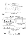
- Fig. 8 For each system, the resulting averaged power loss distribution of the individual elements in a phase leg for 48 kHz switching frequency operation is shown in Fig. 8 .
- Fig. 9 the simulated junction temperatures T J for the proposed VSC system operating in mode 2 and for other 3-level VSC systems are shown in Fig. 9 , where a constant ambient temperature, T A , of 50°C is assumed in the analysis.
- T A constant ambient temperature
- T HS The temperature distribution across the heat sink, T HS , is regarded as uniformly distributed.
- the loss distribution across the switches of the T-type inverter are very different. Additionally, among the 3-level topologies, this system exhibits the lowest efficiency, ⁇ T .
- the 3-level A-NPC achieves an outstanding loss distribution performance, enabling the main semiconductor chips for IGBTs or diodes to operate with similar junction temperatures.
- the A-NPC and the conventional NPC systems display very similar total semiconductor loss, P T . This happens, because in both systems during each commutation one diode and one active switch always experience essential switching and conduction losses (see Reference (4)).
- the new 3-level system operating in mode 1 can always achieve higher efficiency than a conventional NPC, T-type NPC and/or A-NPC.
- the power losses across the transistors T 1 , T 2 , T 3 and T 4 are not equalized.
- the New 3-level VSC operating with balanced loss (mode 2) only displays better performance than the A-NPC for switching frequencies below 25kHz. Due to the fact that the A-NPC cannot balance the losses across the auxiliary switches, a better thermal distribution among all the devices could be achieved with the new system.
- the loss balancing algorithm of Table III aims to distribute the losses between T 1 and T 2 (T 3 and T 4 ), but it does not permit the auxiliary switches to be more thermally stressed than these devices. This is the reason that the junction temperature T J across the NPC switches are not even for the 48 kHz operation (see Fig. 9 ). In fact, without the loss limitation of the auxiliary switches, the thermal profile of the switches T 1 and T 2 (T 3 and T 4 ) would be indeed equalized; however the auxiliary switches would face very high losses during high operating switching frequency.
- Fig. 10(a) and 10(b) show 5- and 7-level VSC configurations, respectively, comprising auxiliary switches T Ax1 -T Ax4 and transistors T 1 -T 8 , and auxiliary switches T Ax1 -T Ax6 and transistors T 1 -T 12 , respectively.
- FIG. 11 Other new 3-level VSCs featuring loss balancing characteristics are shown in Fig. 11 .
- Fig. 11 For instance, adding up to two extra active switches per phase leg of the active NPC of Fig. 1 (d) (T Ax1 and T Ax2 ), a very high efficient 3-level VSC topology with outstanding semiconductor loss distribution is derived. This topology is shown in Fig. 11(a) .
- Fig. 11(a) shows Eventually, in this relatively complex topology, multiple additional switching states and new commutation possibilities are incorporated to the conventional NPC, which gives much more controllability of the semiconductor losses when compared to the A-NPC (see Fig. 1 (d) ) or the new 3-level VSC (see Fig. 2(a) ).
- FIG. 11 (b) A new voltage source converters featuring loss balancing characteristics based on a T-type NPC VSC is proposed in Fig. 11 (b) .
- An alternative configuration of the new 3-level VSC (see Fig. 2(a) ) is shown in Fig. 11 (c) .
- Fig. 11 (d) An alternative configuration for the 3-level converter presented in Fig. 11 (a) is shown in Fig. 11 (d) .
Landscapes
- Engineering & Computer Science (AREA)
- Power Engineering (AREA)
- Inverter Devices (AREA)
Priority Applications (3)
| Application Number | Priority Date | Filing Date | Title |
|---|---|---|---|
| EP11187801.3A EP2590312A1 (fr) | 2011-11-04 | 2011-11-04 | Convertisseur de source de tension avec topologie clampée en neutre modifiée et procédé de fonctionnement d'un tel convertisseur |
| CN201210482787.0A CN103095168B (zh) | 2011-11-04 | 2012-11-05 | 具有中性点钳位拓扑的电压源转换器及其操作方法 |
| US13/669,058 US9543855B2 (en) | 2011-11-04 | 2012-11-05 | Voltage source converter (VSC) with neutral-point-clamped (NPC) topology and method for operating such voltage source converter |
Applications Claiming Priority (1)
| Application Number | Priority Date | Filing Date | Title |
|---|---|---|---|
| EP11187801.3A EP2590312A1 (fr) | 2011-11-04 | 2011-11-04 | Convertisseur de source de tension avec topologie clampée en neutre modifiée et procédé de fonctionnement d'un tel convertisseur |
Publications (1)
| Publication Number | Publication Date |
|---|---|
| EP2590312A1 true EP2590312A1 (fr) | 2013-05-08 |
Family
ID=44905669
Family Applications (1)
| Application Number | Title | Priority Date | Filing Date |
|---|---|---|---|
| EP11187801.3A Ceased EP2590312A1 (fr) | 2011-11-04 | 2011-11-04 | Convertisseur de source de tension avec topologie clampée en neutre modifiée et procédé de fonctionnement d'un tel convertisseur |
Country Status (3)
| Country | Link |
|---|---|
| US (1) | US9543855B2 (fr) |
| EP (1) | EP2590312A1 (fr) |
| CN (1) | CN103095168B (fr) |
Cited By (10)
| Publication number | Priority date | Publication date | Assignee | Title |
|---|---|---|---|---|
| EP2814152A3 (fr) * | 2013-06-14 | 2015-04-29 | Hamilton Sundstrand Corporation | Procédé de dérivation de signaux de courant de commutation dans un redresseur |
| EP2871765A1 (fr) * | 2013-11-08 | 2015-05-13 | Vincotech GmbH | Convertisseur NPC destiné à être utilisé dans un module de puissance et ledit module incorporant celui-ci |
| EP2975755A1 (fr) * | 2014-07-14 | 2016-01-20 | Hamilton Sundstrand Corporation | Convertisseurs de puissance a semi-conducteurs |
| US9318974B2 (en) | 2014-03-26 | 2016-04-19 | Solaredge Technologies Ltd. | Multi-level inverter with flying capacitor topology |
| EP3035509A3 (fr) * | 2014-12-18 | 2016-08-03 | Sungrow Power Supply Co., Ltd. | Procédé et dispositif pour la commutation de mode de fonctionnement d'un onduleur à cinq niveaux |
| US9941813B2 (en) | 2013-03-14 | 2018-04-10 | Solaredge Technologies Ltd. | High frequency multi-level inverter |
| EP3382881A4 (fr) * | 2015-12-23 | 2018-11-21 | Huawei Technologies Co., Ltd. | Transistor équivalent et onduleur à trois niveaux |
| EP3657661A4 (fr) * | 2017-08-11 | 2020-07-15 | Huawei Technologies Co., Ltd. | Circuit de conversion, procédé de commande, et dispositif d'alimentation électrique |
| PL442656A1 (pl) * | 2022-10-27 | 2024-04-29 | Akademia Górniczo-Hutnicza im. Stanisława Staszica w Krakowie | Wielopoziomowy jednofazowy falownik napięcia z poziomowaniem diodowym, o zminimalizowanej liczbie tranzystorów |
| PL442655A1 (pl) * | 2022-10-27 | 2024-04-29 | Akademia Górniczo-Hutnicza im. Stanisława Staszica w Krakowie | Wielopoziomowy falownik napięcia z poziomowaniem diodowym, o zminimalizowanej liczbie tranzystorów |
Families Citing this family (50)
| Publication number | Priority date | Publication date | Assignee | Title |
|---|---|---|---|---|
| US8929114B2 (en) * | 2011-02-24 | 2015-01-06 | Virginia Tech Intellectual Properties, Inc. | Three-level active neutral point clamped zero voltage switching converter |
| US9425705B2 (en) | 2012-08-13 | 2016-08-23 | Rockwell Automation Technologies, Inc. | Method and apparatus for bypassing cascaded H-bridge (CHB) power cells and power sub cell for multilevel inverter |
| US9240731B2 (en) | 2013-03-18 | 2016-01-19 | Rockwell Automation Technologies, Inc. | Power cell bypass method and apparatus for multilevel inverter |
| US9397584B2 (en) * | 2013-09-25 | 2016-07-19 | Eaton Corporation | Multi-level converter apparatus and methods using clamped node bias |
| CN105829225B (zh) * | 2013-12-18 | 2019-11-05 | 奥的斯电梯公司 | 用于再生驱动器的总线电容器组配置 |
| JP5935789B2 (ja) * | 2013-12-24 | 2016-06-15 | トヨタ自動車株式会社 | 電力変換装置及び電力変換方法 |
| US9520800B2 (en) * | 2014-01-09 | 2016-12-13 | Rockwell Automation Technologies, Inc. | Multilevel converter systems and methods with reduced common mode voltage |
| US9325252B2 (en) | 2014-01-13 | 2016-04-26 | Rockwell Automation Technologies, Inc. | Multilevel converter systems and sinusoidal pulse width modulation methods |
| CN104811073B (zh) * | 2014-01-24 | 2019-05-31 | 通用电气能源电能变换科技有限公司 | 变换器模块、装置、系统和相关方法 |
| DE102014203404B4 (de) * | 2014-02-25 | 2023-11-16 | Fraunhofer-Gesellschaft zur Förderung der angewandten Forschung e.V. | Stromrichterschaltung und Verfahren zum Betreiben derselben |
| EP3002867B1 (fr) * | 2014-10-01 | 2019-12-04 | ABB Schweiz AG | Convertisseur à trois niveaux et procédé pour commander un convertisseur à trois niveaux |
| US9559541B2 (en) | 2015-01-15 | 2017-01-31 | Rockwell Automation Technologies, Inc. | Modular multilevel converter and charging circuit therefor |
| US9748862B2 (en) | 2015-05-13 | 2017-08-29 | Rockwell Automation Technologies, Inc. | Sparse matrix multilevel actively clamped power converter |
| US9871467B2 (en) * | 2016-05-19 | 2018-01-16 | Abb Schweiz Ag | Resonant converters including flying capacitors |
| CN107707139B (zh) * | 2016-08-08 | 2020-05-01 | 维谛技术有限公司 | 一种具有开关桥臂的电路的控制方法及装置 |
| US9812990B1 (en) | 2016-09-26 | 2017-11-07 | Rockwell Automation Technologies, Inc. | Spare on demand power cells for modular multilevel power converter |
| CN107888100B (zh) * | 2016-09-30 | 2019-12-20 | 维谛技术有限公司 | 一种逆变器、控制逆变器的方法及控制装置 |
| US10063161B2 (en) * | 2016-10-18 | 2018-08-28 | Abb Schweiz Ag | Active neutral point clamped converter control system and method |
| US9979291B2 (en) * | 2016-10-26 | 2018-05-22 | Futurewei Technologies, Inc. | Inverter apparatus |
| DE102016222001A1 (de) * | 2016-11-09 | 2018-05-09 | Vincotech Gmbh | Aktives drei-pegel-npc-wandlermodul |
| JP6775118B2 (ja) * | 2016-12-01 | 2020-10-28 | パナソニックIpマネジメント株式会社 | 電力変換回路 |
| WO2018113944A1 (fr) * | 2016-12-21 | 2018-06-28 | Abb Schweiz Ag | Convertisseur de source de tension à fonctionnement amélioré |
| TWI627828B (zh) | 2017-03-13 | 2018-06-21 | 台達電子工業股份有限公司 | 電源轉換器與電源轉換方法 |
| US10097109B1 (en) * | 2017-07-19 | 2018-10-09 | Futurewei Technologies, Inc. | Three-level voltage bus apparatus and method |
| US10291150B1 (en) | 2017-11-08 | 2019-05-14 | General Electric Company | Method and system for operating a phase-leg of a three-level active neutral point clamped converter |
| CN108429477B (zh) * | 2018-02-02 | 2020-12-11 | 华北电力大学 | 一种基于双半桥和并联全桥混合的mmc子模块优化均压方法 |
| US10158299B1 (en) | 2018-04-18 | 2018-12-18 | Rockwell Automation Technologies, Inc. | Common voltage reduction for active front end drives |
| CN108667327B (zh) * | 2018-05-03 | 2020-03-20 | 华为数字技术(苏州)有限公司 | 多电平逆变器 |
| CN110707957B (zh) * | 2018-07-10 | 2021-07-06 | 台达电子工业股份有限公司 | 具有过流保护控制的换流装置 |
| CN110855174B (zh) * | 2018-07-27 | 2021-08-06 | 台达电子工业股份有限公司 | 逆变器装置及其控制方法 |
| CN109372698A (zh) * | 2018-10-18 | 2019-02-22 | 明阳智慧能源集团股份公司 | 一种风力发电系统 |
| US10547251B1 (en) | 2018-11-15 | 2020-01-28 | General Electric Company | Method for shutdown of an active neutral point clamped converter |
| CN109742968B (zh) * | 2019-01-31 | 2020-12-04 | 上海交通大学 | 二极管箝位混合三电平双有源全桥变流器及其控制方法 |
| CN110061646B (zh) * | 2019-05-22 | 2021-05-04 | 深圳市德力电气技术有限公司 | 一种三电平逆变器中点平衡的方法、设备及存储介质 |
| CN113261191B (zh) * | 2019-06-26 | 2023-05-05 | 华为数字能源技术有限公司 | 双向多端口功率转换系统及方法 |
| US11211879B2 (en) | 2019-09-23 | 2021-12-28 | Rockwell Automation Technologies, Inc. | Capacitor size reduction and lifetime extension for cascaded H-bridge drives |
| WO2021108604A1 (fr) * | 2019-11-27 | 2021-06-03 | Wayne State University | Onduleur à sept niveaux monophasés |
| CN112202353B (zh) * | 2020-08-25 | 2022-07-01 | 远景能源有限公司 | 双馈变频器及其调制方法 |
| US11159095B1 (en) * | 2020-11-12 | 2021-10-26 | King Abdulaziz University | 11-level boost active neutral point clamped inverter topology with higher voltage gain |
| CN113114061B (zh) * | 2021-03-26 | 2022-06-24 | 台达电子企业管理(上海)有限公司 | 变换器及抑制变换器的环流干扰的方法 |
| US11342878B1 (en) | 2021-04-09 | 2022-05-24 | Rockwell Automation Technologies, Inc. | Regenerative medium voltage drive (Cascaded H Bridge) with reduced number of sensors |
| US11831232B2 (en) | 2021-08-13 | 2023-11-28 | General Electric Company | Power converter having a gate drive circuit and method of operating |
| CN114499253B (zh) * | 2022-02-17 | 2023-05-02 | 东南大学 | 一种适用于中点箝位三电平变流器桥臂开关管损耗均衡的调制策略及其实现方法 |
| US12176703B2 (en) | 2022-03-04 | 2024-12-24 | Innoscience (suzhou) Semiconductor Co., Ltd. | Terminal protection network and electronic device |
| CN115411918A (zh) * | 2022-08-10 | 2022-11-29 | 华为数字能源技术有限公司 | 逆变器及其控制方法、以及供电系统 |
| CN115065223B (zh) * | 2022-08-18 | 2022-11-29 | 杭州飞仕得科技有限公司 | 一种有源钳位三电平电路的优化控制方法和装置 |
| CN115987128A (zh) * | 2023-02-17 | 2023-04-18 | 阳光电源股份有限公司 | 一种变换器及其anpc电路驱动方法 |
| KR102754698B1 (ko) * | 2023-07-31 | 2025-01-14 | 국립군산대학교산학협력단 | 3-레벨 btb npc 컨버터를 위한 3차원 svpwm 스위칭 조정 방법 및 장치 |
| TWI880437B (zh) * | 2023-11-07 | 2025-04-11 | 台達電子工業股份有限公司 | 三階層功因整流器及其操作方法 |
| US12565111B1 (en) | 2025-03-05 | 2026-03-03 | dcbel Inc. | Bidirectional split-phase power converter for electric vehicle charging |
Citations (6)
| Publication number | Priority date | Publication date | Assignee | Title |
|---|---|---|---|---|
| US4270163A (en) | 1978-09-21 | 1981-05-26 | Exxon Research & Engineering Company | Bridge converter circuit |
| US20110013438A1 (en) * | 2009-07-20 | 2011-01-20 | Michael Frisch | inverter topologies usable with reactive power |
| DE102009039195A1 (de) * | 2009-08-28 | 2011-03-03 | Converteam Gmbh | N-stufiger elektrischer Stromrichter |
| US20110193412A1 (en) * | 2010-02-05 | 2011-08-11 | Mge Ups | Converter device and uninterruptible power supply equipped with such a device |
| WO2011154506A2 (fr) * | 2010-06-12 | 2011-12-15 | Kostal Industrie Elektrik Gmbh | Topologie de circuit pour connexion de phase d'un onduleur |
| EP2413489A1 (fr) * | 2010-07-30 | 2012-02-01 | Vinotech Holdings S.à.r.l. | Convertisseur courant continu courant alternatif à demi-pont hautement efficace |
Family Cites Families (10)
| Publication number | Priority date | Publication date | Assignee | Title |
|---|---|---|---|---|
| SE511219C2 (sv) * | 1998-01-27 | 1999-08-23 | Asea Brown Boveri | Omriktare där klampningsdioderna ersatts av en aktiv klampningskrets |
| CN100492856C (zh) * | 1999-08-12 | 2009-05-27 | 株式会社安川电机 | 三相中性点钳位式pwm逆变器装置 |
| DE50110556D1 (de) * | 2000-09-13 | 2006-09-07 | Abb Research Ltd | Steuer- und regelverfahren für einen dreipunkt-stromrichter mit aktiven klemmschaltern sowie vorrichtung hierzu |
| SE524014C2 (sv) * | 2002-10-09 | 2004-06-15 | Abb Ab | Omriktare samt förfarande för styrning av en omriktare |
| EP1756926B1 (fr) * | 2004-06-18 | 2007-11-07 | ABB Schweiz AG | Procede de traitement de defaut dans un circuit convertisseur pour la commutation de trois niveaux de tension |
| WO2006000111A1 (fr) * | 2004-06-23 | 2006-01-05 | Abb Schweiz Ag | Circuit commutateur polyphase pauvre en oscillations harmoniques |
| US8427010B2 (en) * | 2009-05-29 | 2013-04-23 | General Electric Company | DC-to-AC power conversion system and method |
| CN101599713B (zh) * | 2009-07-07 | 2011-09-14 | 华中科技大学 | 一种单相混合桥三电平逆变器 |
| US9312705B2 (en) * | 2010-12-22 | 2016-04-12 | Ge Energy Power Conversion Technology Limited | Capacitor balancing circuit and control method for an electronic device such as a multilevel power inverter |
| US8570776B2 (en) * | 2011-05-27 | 2013-10-29 | Alstom Technology Ltd | Method and device for determining a control scheme for an active power filter |
-
2011
- 2011-11-04 EP EP11187801.3A patent/EP2590312A1/fr not_active Ceased
-
2012
- 2012-11-05 US US13/669,058 patent/US9543855B2/en not_active Expired - Fee Related
- 2012-11-05 CN CN201210482787.0A patent/CN103095168B/zh not_active Expired - Fee Related
Patent Citations (6)
| Publication number | Priority date | Publication date | Assignee | Title |
|---|---|---|---|---|
| US4270163A (en) | 1978-09-21 | 1981-05-26 | Exxon Research & Engineering Company | Bridge converter circuit |
| US20110013438A1 (en) * | 2009-07-20 | 2011-01-20 | Michael Frisch | inverter topologies usable with reactive power |
| DE102009039195A1 (de) * | 2009-08-28 | 2011-03-03 | Converteam Gmbh | N-stufiger elektrischer Stromrichter |
| US20110193412A1 (en) * | 2010-02-05 | 2011-08-11 | Mge Ups | Converter device and uninterruptible power supply equipped with such a device |
| WO2011154506A2 (fr) * | 2010-06-12 | 2011-12-15 | Kostal Industrie Elektrik Gmbh | Topologie de circuit pour connexion de phase d'un onduleur |
| EP2413489A1 (fr) * | 2010-07-30 | 2012-02-01 | Vinotech Holdings S.à.r.l. | Convertisseur courant continu courant alternatif à demi-pont hautement efficace |
Non-Patent Citations (15)
| Title |
|---|
| B. KAKU, . MIYASHITA, S. SONE: "Switching loss minimized space vector pwm method for igbt three-level inverter", LEE PROCEEDINGS. ELECTRIC POWER APPLICATIONS, vol. 144, May 1997 (1997-05-01), pages 182 - 190, XP006008606, DOI: doi:10.1049/ip-epa:19970989 |
| D. FLORICAU, E. FLORICAU, G. GATEAU: "Three-level active NPC converter: PWM strategies and loss distribution", PROC. IEEE IECON, November 2008 (2008-11-01), pages 3333 - 3338 |
| J. LI, A. Q. HUANG, S. BHATTACHARYA, G. TAN: "Three-level active neutral-point-clamped (ANPC) converter with fault tolerance ability", PROC. IEEE APEC, February 2009 (2009-02-01), pages 840 - 845, XP031442780 |
| J. RODRIGUEZ, S. BERNET, P. K. STEIMER, E. LIZAMA: "A survey on neutral-point-clamped inverters", IEEE TRANS. IND. ELECTRON., vol. 57, no. 7, July 2010 (2010-07-01), pages 2219 - 2230, XP011295886 |
| M. SCHWEIZER, LIZAMA, T. FRIEDLI, J. W. KOLAR: "Comparison of the chip area usage of 2-level and 3-level voltage source converter topologies", PROC. 36TH ANNUAL CONF. OF IEEE INDUSTRIAL ELECTRONICS (IECON, 2010 |
| M. SCHWEIZER, T. FRIEDLI, J. W. KOLAR: "Comparison and implementation of a 3-level npc voltage link back-to-back converter with sic and si diodes", PROC. TWENTY-FIFTH ANNUAL IEEE APPLIED POWER ELECTRONICS CONF. AND EXPOSITION (APEC, 2010, pages 1527 - 1533, XP031649634 |
| NABAE, TAKAHASHI, H. AKAGI: "A new neutral-point-clamped PWM inverter", IEEE TRANS. IND. APPL., vol. 17, no. 5, September 1981 (1981-09-01), pages 518 - 523, XP011213024 |
| R. TEICHMANN, S. BERNET: "A comparison of three-level converters versus two-level converters for low voltage drives, traction, and utility applications", IEEE TRANS. IND. APPL, vol. 41, May 2005 (2005-05-01), pages 855 - 865, XP011132531, DOI: doi:10.1109/TIA.2005.847285 |
| STUPAR, D. BORTIS, U. DROFENIK, J. W. KOLAR: "Advanced setup for thermal cycling of power modules following definable junction temperature profiles", IPEC, 2010 |
| T. ANZAWA, Q. YU, M. YAMAGIWA, T. SHIBUTANI, M. SHIRATORI: "Power cycle fatigue reliability evaluation for power device using coupled electrical- thermal-mechanical analysis", THERMAL AND THERMOMECHANICAL PHENOMENA IN ELECTRONIC SYSTEMS, 2008. ITHERM 2008. 11 TH INTERSOCIETY CONFERENCE ON, 28 May 2008 (2008-05-28), pages 815 - 821, XP031273789 |
| T. BRÜCKNER, S. BERNET, H. GÜLDNER: "The active npc converter and its loss-balancing control", IEEE TRANS. IND. ELECTRON., vol. 52, no. 5, June 2005 (2005-06-01), pages 855 - 868, XP011133065, DOI: doi:10.1109/TIE.2005.847586 |
| T. BRÜCKNER, S. BERNET, P. K. STEIMER: "Feedforward loss control of three-level active NPC converters", IEEE TRANS. IND. APPL., vol. 43, no. 6, November 2007 (2007-11-01), pages 1588 - 1596, XP011197468, DOI: doi:10.1109/TIA.2007.908164 |
| T. BRUCKNER, S. BERNET: "Loss balancing in three-level voltage source inverters applying active NPC switches", PROC. IEEE POWER ELECTRON. SPEC. CONF., VANCOUVER, BC, CANADA, 2001, pages 1135 - 1140, XP010559381, DOI: doi:10.1109/PESC.2001.954272 |
| THIAGO B SOEIRO ET AL: "Comparison of 2- and 3-level active filters with enhanced bridge-leg loss distribution", POWER ELECTRONICS AND ECCE ASIA (ICPE&ECCE), 2011 IEEE 8TH INTERNATIONAL CONFERENCE ON, IEEE, 30 May 2011 (2011-05-30), pages 1835 - 1842, XP031956115, ISBN: 978-1-61284-958-4, DOI: 10.1109/ICPE.2011.5944519 * |
| X. YUAN, H. STEMMLER, BARBI: "Investigation on the clamping voltage self-balancing of the three-level capacitor clamping inverter", PROC. IEEE PESC, CHARLESTON, SC, 1999, pages 1059 - 1064, XP000924577, DOI: doi:10.1109/PESC.1999.785642 |
Cited By (31)
| Publication number | Priority date | Publication date | Assignee | Title |
|---|---|---|---|---|
| US11545912B2 (en) | 2013-03-14 | 2023-01-03 | Solaredge Technologies Ltd. | High frequency multi-level inverter |
| US9941813B2 (en) | 2013-03-14 | 2018-04-10 | Solaredge Technologies Ltd. | High frequency multi-level inverter |
| US11742777B2 (en) | 2013-03-14 | 2023-08-29 | Solaredge Technologies Ltd. | High frequency multi-level inverter |
| US12119758B2 (en) | 2013-03-14 | 2024-10-15 | Solaredge Technologies Ltd. | High frequency multi-level inverter |
| EP2814152A3 (fr) * | 2013-06-14 | 2015-04-29 | Hamilton Sundstrand Corporation | Procédé de dérivation de signaux de courant de commutation dans un redresseur |
| US9362844B2 (en) | 2013-06-14 | 2016-06-07 | Hamilton Sundstrand Corporation | Method of deriving switch current signals in a rectifier |
| EP2871765A1 (fr) * | 2013-11-08 | 2015-05-13 | Vincotech GmbH | Convertisseur NPC destiné à être utilisé dans un module de puissance et ledit module incorporant celui-ci |
| US10886831B2 (en) | 2014-03-26 | 2021-01-05 | Solaredge Technologies Ltd. | Multi-level inverter |
| US10886832B2 (en) | 2014-03-26 | 2021-01-05 | Solaredge Technologies Ltd. | Multi-level inverter |
| US10153685B2 (en) | 2014-03-26 | 2018-12-11 | Solaredge Technologies Ltd. | Power ripple compensation |
| US11632058B2 (en) | 2014-03-26 | 2023-04-18 | Solaredge Technologies Ltd. | Multi-level inverter |
| US12136890B2 (en) | 2014-03-26 | 2024-11-05 | Solaredge Technologies Ltd. | Multi-level inverter |
| US10404154B2 (en) | 2014-03-26 | 2019-09-03 | Solaredge Technologies Ltd | Multi-level inverter with flying capacitor topology |
| US10680505B2 (en) | 2014-03-26 | 2020-06-09 | Solaredge Technologies Ltd. | Multi-level inverter |
| US11296590B2 (en) | 2014-03-26 | 2022-04-05 | Solaredge Technologies Ltd. | Multi-level inverter |
| US11855552B2 (en) | 2014-03-26 | 2023-12-26 | Solaredge Technologies Ltd. | Multi-level inverter |
| US9318974B2 (en) | 2014-03-26 | 2016-04-19 | Solaredge Technologies Ltd. | Multi-level inverter with flying capacitor topology |
| US10680506B2 (en) | 2014-03-26 | 2020-06-09 | Solaredge Technologies Ltd. | Multi-level inverter |
| US10700588B2 (en) | 2014-03-26 | 2020-06-30 | Solaredge Technologies Ltd. | Multi-level inverter |
| EP2975755A1 (fr) * | 2014-07-14 | 2016-01-20 | Hamilton Sundstrand Corporation | Convertisseurs de puissance a semi-conducteurs |
| US10243482B2 (en) | 2014-07-14 | 2019-03-26 | Hamilton Sundstrand Corporation | Solid-state power converters |
| EP3035509A3 (fr) * | 2014-12-18 | 2016-08-03 | Sungrow Power Supply Co., Ltd. | Procédé et dispositif pour la commutation de mode de fonctionnement d'un onduleur à cinq niveaux |
| US9712083B2 (en) | 2014-12-18 | 2017-07-18 | Sungrow Power Supply Co., Ltd. | Method and device for switching operation mode of a five-level inverter |
| EP3382881A4 (fr) * | 2015-12-23 | 2018-11-21 | Huawei Technologies Co., Ltd. | Transistor équivalent et onduleur à trois niveaux |
| US10333427B2 (en) | 2015-12-23 | 2019-06-25 | Huawei Technologies Co., Ltd. | Equivalent transistor and three-level inverter |
| US11201565B2 (en) | 2017-08-11 | 2021-12-14 | Huawei Technologies Co., Ltd. | Conversion circuit, control method, and power supply device |
| EP3657661A4 (fr) * | 2017-08-11 | 2020-07-15 | Huawei Technologies Co., Ltd. | Circuit de conversion, procédé de commande, et dispositif d'alimentation électrique |
| PL442656A1 (pl) * | 2022-10-27 | 2024-04-29 | Akademia Górniczo-Hutnicza im. Stanisława Staszica w Krakowie | Wielopoziomowy jednofazowy falownik napięcia z poziomowaniem diodowym, o zminimalizowanej liczbie tranzystorów |
| PL442655A1 (pl) * | 2022-10-27 | 2024-04-29 | Akademia Górniczo-Hutnicza im. Stanisława Staszica w Krakowie | Wielopoziomowy falownik napięcia z poziomowaniem diodowym, o zminimalizowanej liczbie tranzystorów |
| EP4362313A1 (fr) | 2022-10-27 | 2024-05-01 | Akademia Gorniczo-Hutnicza im. Stanislawa Staszica w Krakowie | Onduleur de tension multiniveaux a diode de clamping avec un nombre de transistors reduit. |
| EP4362312A1 (fr) | 2022-10-27 | 2024-05-01 | Akademia Gorniczo-Hutnicza im. Stanislawa Staszica w Krakowie | Onduleur de tension multiniveaux a diode de clamping avec un nombre de transistors reduit. |
Also Published As
| Publication number | Publication date |
|---|---|
| CN103095168A (zh) | 2013-05-08 |
| US20130272045A1 (en) | 2013-10-17 |
| CN103095168B (zh) | 2016-01-06 |
| US9543855B2 (en) | 2017-01-10 |
Similar Documents
| Publication | Publication Date | Title |
|---|---|---|
| US9543855B2 (en) | Voltage source converter (VSC) with neutral-point-clamped (NPC) topology and method for operating such voltage source converter | |
| Soeiro et al. | The new high-efficiency hybrid neutral-point-clamped converter | |
| Marzoughi et al. | Investigating impact of emerging medium-voltage SiC MOSFETs on medium-voltage high-power industrial motor drives | |
| Barater et al. | Performance evaluation of a three-level ANPC photovoltaic grid-connected inverter with 650-V SiC devices and optimized PWM | |
| Sarnago et al. | Design and implementation of a high-efficiency multiple-output resonant converter for induction heating applications featuring wide bandgap devices | |
| Belkhode et al. | Enhanced hybrid active-neutral-point-clamped converter with optimized loss distribution-based modulation scheme | |
| Schweizer et al. | Heatsink-less Quasi 3-level flying capacitor inverter based on low voltage SMD MOSFETs | |
| CN102347702B (zh) | 高效半桥直流到交流转换器 | |
| Stecca et al. | Hybrid Si/SiC switch modulation with minimum SiC MOSFET conduction in grid connected voltage source converters | |
| EP2584691B1 (fr) | Module convertisseur 3-niveaux NPC | |
| EP2728734A1 (fr) | Onduleur fixé au point neutre à trois niveaux | |
| Dai et al. | Integrated motor drive using soft-switching current-source inverters with SiC-and GaN-based bidirectional switches | |
| Zhao et al. | An enhanced modulation scheme for multi-level T-type inverter with loss balance and reduction | |
| Soeiro et al. | High voltage photovoltaic system implementing Si/SiC-based active neutral-point-clamped converter | |
| Ulissi et al. | High-frequency operation of series-connected IGCTs for resonant converters | |
| CA2778072A1 (fr) | Methode de determination de modele de controle de npc vsc, plus particulierement comme filtre d'alimentation actif | |
| KR20140013863A (ko) | 3-레벨 중성점 클램핑 다이오드 인버터 회로 및 이의 펄스폭 제어 방법 | |
| Modeer et al. | High-voltage tapped-inductor buck converter auxiliary power supply for cascaded converter submodules | |
| Sahan et al. | Combining the benefits of SiC T-MOSFET and Si IGBT in a novel ANPC power module for highly compact 1500-V grid-tied inverters | |
| Liu et al. | Conduction time variation-based active thermal control method for Si and SiC hybrid switch | |
| Satpathy et al. | Power layout design of a GaN HEMTs-based high-power high-efficiency three-level ANPC inverter for 800 V DC bus system | |
| Woldegiorgis et al. | A high efficiency three-level active neutral point clamped inverter using hybrid Si/SiC switches | |
| Lim et al. | Design of 100 kVA SiC power converter for aircraft electric starter generator | |
| Honório et al. | Three-leg integrated stage AC–DC solid-state transformer feasible for MV railway applications | |
| Soeiro et al. | Novel 3-level hybrid neutral-point-clamped converter |
Legal Events
| Date | Code | Title | Description |
|---|---|---|---|
| PUAI | Public reference made under article 153(3) epc to a published international application that has entered the european phase |
Free format text: ORIGINAL CODE: 0009012 |
|
| AK | Designated contracting states |
Kind code of ref document: A1 Designated state(s): AL AT BE BG CH CY CZ DE DK EE ES FI FR GB GR HR HU IE IS IT LI LT LU LV MC MK MT NL NO PL PT RO RS SE SI SK SM TR |
|
| AX | Request for extension of the european patent |
Extension state: BA ME |
|
| 17P | Request for examination filed |
Effective date: 20131023 |
|
| RBV | Designated contracting states (corrected) |
Designated state(s): AL AT BE BG CH CY CZ DE DK EE ES FI FR GB GR HR HU IE IS IT LI LT LU LV MC MK MT NL NO PL PT RO RS SE SI SK SM TR |
|
| RAP1 | Party data changed (applicant data changed or rights of an application transferred) |
Owner name: GENERAL ELECTRIC TECHNOLOGY GMBH |
|
| 17Q | First examination report despatched |
Effective date: 20160804 |
|
| STAA | Information on the status of an ep patent application or granted ep patent |
Free format text: STATUS: THE APPLICATION HAS BEEN REFUSED |
|
| 18R | Application refused |
Effective date: 20181203 |