EP2590493A2 - Convertisseur de fréquence - Google Patents
Convertisseur de fréquence Download PDFInfo
- Publication number
- EP2590493A2 EP2590493A2 EP12191573.0A EP12191573A EP2590493A2 EP 2590493 A2 EP2590493 A2 EP 2590493A2 EP 12191573 A EP12191573 A EP 12191573A EP 2590493 A2 EP2590493 A2 EP 2590493A2
- Authority
- EP
- European Patent Office
- Prior art keywords
- power electronics
- electronics module
- heat
- heat sink
- recess
- Prior art date
- Legal status (The legal status is an assumption and is not a legal conclusion. Google has not performed a legal analysis and makes no representation as to the accuracy of the status listed.)
- Granted
Links
Images


Classifications
-
- H—ELECTRICITY
- H05—ELECTRIC TECHNIQUES NOT OTHERWISE PROVIDED FOR
- H05K—PRINTED CIRCUITS; CASINGS OR CONSTRUCTIONAL DETAILS OF ELECTRIC APPARATUS; MANUFACTURE OF ASSEMBLAGES OF ELECTRICAL COMPONENTS
- H05K7/00—Constructional details common to different types of electric apparatus
- H05K7/20—Modifications to facilitate cooling, ventilating, or heating
- H05K7/2089—Modifications to facilitate cooling, ventilating, or heating for power electronics, e.g. for inverters for controlling motor
- H05K7/209—Heat transfer by conduction from internal heat source to heat radiating structure
-
- H—ELECTRICITY
- H05—ELECTRIC TECHNIQUES NOT OTHERWISE PROVIDED FOR
- H05K—PRINTED CIRCUITS; CASINGS OR CONSTRUCTIONAL DETAILS OF ELECTRIC APPARATUS; MANUFACTURE OF ASSEMBLAGES OF ELECTRICAL COMPONENTS
- H05K7/00—Constructional details common to different types of electric apparatus
- H05K7/14—Mounting supporting structure in casing or on frame or rack
- H05K7/1422—Printed circuit boards receptacles, e.g. stacked structures, electronic circuit modules or box like frames
- H05K7/1427—Housings
- H05K7/1432—Housings specially adapted for power drive units or power converters
Definitions
- the invention relates to a frequency converter with a circuit board, a power electronics module mounted thereon and a heat sink.
- a frequency converter with a circuit board, a power electronics module mounted thereon and a heat sink.
- the provided on the bottom contact portions of the power electronics module are soldered to the board.
- the power electronics module also has a heat extraction surface, which includes an angle of 90 ° (+/- 10 °) with a main plane of extension of the board.
- the heat sink has a heat coupling surface, which rests flat against the heat extraction surface of the power electronics module.
- Power electronics modules for a generic frequency converter which in the present case can be, in particular, IGBT modules ("insulated gate bipolar transistor"), are available, for example, from the manufacturer Tyco.
- IGBT modules insulated gate bipolar transistor
- the said heat extraction surface is not on the opposite side to the arranged with the board bottom of the power electronics module, but with this bottom encloses a right angle.
- the heat sink is arranged so that its heat input surface also extends orthogonal to the main extension plane of the board. The surface normals of the heat input surface and the board thus include a right angle.
- This type of power electronics modules allows a comparatively flat design of the frequency converter.
- the object of the invention is to develop a generic frequency converter to the effect that this allows easier installation and / or difficult disassembly.
- the at least one screw for pressing the heat sink on the power electronics module extends from the side of the heat sink through a first recess in the heat sink into a second recess on the power electronics module and into a recess in the second recess or in a provided behind the second recess internal thread is screwed.
- the screw does not protrude in the direction of the screw head to the distal end of the screw thread from the power electronics module in the heat sink and an optionally there to be arranged mother, but has from the direction of the heat sink in the direction of the power electronics module.
- a screw from the heat sink by a provided in the heat sink opening, such as a through hole passed.
- This screw protrudes in the direction of its distal end through a second recess on the power electronics module, which in the simplest case may be an internal thread provided directly on the power electronics module.
- the complicated handling of a nut in the region of the heat sink is thus eliminated.
- the screwing takes place on the side of the heat sink, so that the handling of a screwing tool in the immediate vicinity of the board can be omitted.
- Another advantage, which is achieved by the design according to the invention, is that the assembly order can thereby be made more free. This applies to the case that components or additional boards are provided on the side of the board, which makes screwing the power electronics module from this side very difficult or impossible. In such cases, the attachment of the power electronics modules on the heat sink has been made early on so as to then mount the other components or additional boards. In contrast, the solution according to the invention allows the completion of the board before its attachment to the heat sink.
- a power electronics module is understood as meaning a module having a housing and power electronics components contained therein.
- the housing is preferably a plastic housing having a metallic outer surface which forms the heat extraction surface.
- This power electronics module to be used in the context of this invention is adapted to be soldered onto a circuit board in the manner described.
- the preferably metallic heat sink is a metallic body which has a significantly increased surface area relative to the heat extraction surface, thereby improving the release of heat into an environment.
- the heat sink is at the same time that part of the frequency converter, the attachment means, such as holes available provides that allow attachment to a mounting surface such as a cabinet wall.
- a separate holding device can also be provided independent of the power electronics module is attached by its own solder joint on the board.
- the internal thread may be an integral part of this holding device, ie in particular be cut into a sheet from which the holding device has been produced. It is also possible instead that a nut is secured against rotation on the holding device, which in turn provides the internal thread.
- the holding device is preferably as well as the power electronics module soldered to the board. Thus, it can be connected in the course of a uniform manufacturing step together with the power electronics module to the board.
- the power electronics module requires compared to conventional Forms of no adaptation.
- the provided on the side of the power electronics module thread is provided in a separate manner by the holding device.
- At least two holding devices are provided which are each connected by means of a solder connection to the board and each having an internal thread for a screwed-in from the side of the heat sink from screw. It is provided that the at least two screws are both extending through a respective second recess on the heat sink and are screwed beyond this respective recess in the internal thread of each of the holding devices.
- the holding devices may be formed as separate holding devices, which are each secured to the motherboard. However, it has proven to be advantageous if the two holding devices are connected to each other via a cross-member, which spans the power electronics module. In such a case, thus a power electronics module spanning fastening device is provided, which combines as it were the two mentioned holding devices in itself. The traverse causes a separation of the power electronics module is made difficult from the board. At the same time, the holding devices interconnected by means of the traverse are additionally stabilized.
- the invention also relates to a power electronics module which is suitable for a frequency converter according to the invention.
- a power electronics module comprises a housing, in particular a plastic housing, housed in the housing power electronic components such as in particular transistors, a bottom with for soldering on a circuit board provided contact portions and a heat extraction surface, which encloses with the bottom an angle of 90 ° (+/- 10 °).
- At least one threaded hole for coupling the power electronics module to a heat sink is provided on the housing. This threaded bore extends orthogonally to the heat extraction surface and is accessible from the direction of the heat extraction surface.
- This threaded hole which may be formed for example by means of a fixed to the housing of the power electronics module and this toolless unsolvable threaded sleeve, makes this directly usable for use in a frequency converter according to the invention. Also included in this design is a power electronics module which has a rotationally secured nut, which in turn provides the internal thread.
- a set can be used, which is also included in the invention.
- Such a set comprises a per se known power electronics module with a housing, housed in the housing power electronic components, a bottom with provided for soldering on a board contact portions, a heat extraction surface with the bottom an angle of 90 ° (+/- 10 ° ) and at least one recess, wherein the recess for receiving a screw is formed orthogonal to the heat extraction surface and is accessible from the direction of the heat extraction surface.
- this recess itself preferably has no internal thread.
- Part of the set is therefore also a holding device which can be fastened to the circuit board independently of the power electronics module by means of a soldering connection, an internal thread being provided on the holding device which, when the power electronics module and the fastening device are arranged on the circuit board the same board on the side facing away from a heat sink with the recess can be arranged in alignment.
- the set according to the invention thus comprises the power electronics module itself and the holding device.
- This holding device is relative to the power electronics module to be arranged opposite to the heat sink. It is tuned to the power electronics module such that the spacing of the recess of the power electronics module of the board and the spacing of the internal thread of the holding device of the board is identical, so that after separately soldering the power electronics module on the one hand and the holding device on the other the board is given the opportunity to screw a pointing from the heat sink in the direction of the power electronics module screw through the recess of the power electronics module into the internal thread of the fastening device.
- the internal thread can also be formed inseparably with other parts of the holding device, in particular the attachment region to be soldered to the board, for example by a one-piece design.
- the invention also encompasses a holding device which has a receiving space for a nut which is secured against rotation there, or to which a nut is fastened in a rotationally secured manner in another way.
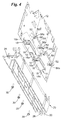
- FIG. 1 shows a frequency converter 10 according to the invention in an overall view, wherein a plastic hood of the frequency converter 10 in the illustration of FIG. 1 already removed. Based on Fig. 1 as well as the detailed representation of Fig. 2 and the exploded view of Fig. 4 the structure of the frequency converter 10 will be explained below.
- Main components of the frequency converter are a circuit board 12, on which various electronic components for frequency conversion are arranged.
- This also includes two IGBT modules 14, based on the representation of the FIG. 1 are provided at the bottom of the board 12.
- the circuit board 12 is screwed in a manner not shown with a heat sink 20.
- This heat sink 20 forms with its side facing away from the board 12 an attachment surface 22, the Attachment is provided on a wall of a cabinet.
- fastening devices 28 are provided in the form of recesses for fastening screws on the heat sink 20.
- the heat to be dissipated via the heat sink 20 is, in particular, that heat loss which is produced at the IGBT modules 14.
- the IGBT modules 14 therefore have their reference to the illustration of the FIG. 1 downwardly facing side a metallic heat extraction surface 16, which in the perspective of the FIG. 1 can not be seen. This is applied to an upwardly facing heat coupling surface 24 of the heat sink 20.
- the heat extraction surface 16 of the IGBT modules 14 and the heat coupling surface 24 of the heat sink 20 must be flush with each other.
- the heat sink 20 and the IGBT modules 14 are not only connected to one another indirectly via the circuit board 12, but are additionally pressed against one another by screw connections with screws 30. These screws 30 extend parallel to the main extension plane of the circuit board 12 and orthogonal to the heat extraction surfaces 16 of the IGBT modules 14 and the heat input surface 24 of the heat sink 20.
- the screws 30 are based on the perspective of FIG. 1 and screwed in the manner illustrated by the arrow 2 in the vertical direction upwards. They extend in the manner explained in more detail below through an opening 26 in the heat sink 20 and a recess or bore 18a on lateral mounting flanges 18 of the IGBT modules 14. Beyond these mounting flanges 18, the screws 30 are screwed into internal thread 56a.
- the two internal threads 56a are not on the IGBT modules 14 provided themselves. Instead, a fixing device 50 is provided for each IGBT module 14. These are designed in the manner of a metal bracket. Each fastening device 50 spans in the particular from FIG. 2 apparent manner of one of the IGBT modules 14th
- each of the fastening devices 50 has two fastening arms 52, which are respectively soldered to the circuit board 12.
- the two attachment arms 52 are connected to each other via the traverse 54 spanning the respective IGBT module 14.
- Attached to the attachment arms 52 are mutually facing fastening tabs 56 which have the said threaded bores 56a or which are provided with nuts having said threaded bores 56a.
- the assembly can be facilitated since the handling of a screwing tool does not have to take place in the immediate vicinity of the circuit board 12. Also, after attaching the frequency converter 10 to a cabinet wall, the accessibility of the screws 30 is severely limited, so that the unscrewing of these screws 30 is made difficult by insufficiently qualified persons.
- FIG. 3 illustrates the structure again in cross section.
- the IGBT module 14 is soldered by means of pin-like contact portions.
- the in this arrangement of this IGBT module 14 and in the representation of the FIG. 3 downwardly facing heat extraction surface 16 is applied to a heat input surface 24 of the heat sink 20 at.
- the desired contact force is achieved via a screw connection.
- screw 30 is provided by the heat sink 20 through a therein Through hole 26, screwed through the recess 18a on the IGBT module 14 into the threaded hole 56a of the fastening device 50.
Landscapes
- Engineering & Computer Science (AREA)
- Microelectronics & Electronic Packaging (AREA)
- Physics & Mathematics (AREA)
- Thermal Sciences (AREA)
- Cooling Or The Like Of Electrical Apparatus (AREA)
Applications Claiming Priority (1)
| Application Number | Priority Date | Filing Date | Title |
|---|---|---|---|
| DE102011085870.9A DE102011085870B4 (de) | 2011-11-07 | 2011-11-07 | Frequenzumrichter |
Publications (3)
| Publication Number | Publication Date |
|---|---|
| EP2590493A2 true EP2590493A2 (fr) | 2013-05-08 |
| EP2590493A3 EP2590493A3 (fr) | 2014-09-17 |
| EP2590493B1 EP2590493B1 (fr) | 2019-03-27 |
Family
ID=47294663
Family Applications (1)
| Application Number | Title | Priority Date | Filing Date |
|---|---|---|---|
| EP12191573.0A Active EP2590493B1 (fr) | 2011-11-07 | 2012-11-07 | Convertisseur de fréquence |
Country Status (2)
| Country | Link |
|---|---|
| EP (1) | EP2590493B1 (fr) |
| DE (1) | DE102011085870B4 (fr) |
Cited By (1)
| Publication number | Priority date | Publication date | Assignee | Title |
|---|---|---|---|---|
| CN103762829B (zh) * | 2014-01-02 | 2016-05-04 | 兰州空间技术物理研究所 | 一种模块化的多路输出电源 |
Families Citing this family (2)
| Publication number | Priority date | Publication date | Assignee | Title |
|---|---|---|---|---|
| DE102017214779B4 (de) * | 2017-08-23 | 2025-09-18 | Lenze Se | Elektrisches Steuergerät |
| DE102019213385A1 (de) | 2019-09-04 | 2021-03-04 | Zf Friedrichshafen Ag | Steuergerät zum Betreiben eines Elektroantriebs für ein Fahrzeug und Verfahren zum Herstellen eines deratigen Steuergeräts |
Family Cites Families (8)
| Publication number | Priority date | Publication date | Assignee | Title |
|---|---|---|---|---|
| DE3929701A1 (de) | 1989-09-07 | 1991-03-14 | Standard Elektrik Lorenz Ag | Steckbare baugruppe |
| WO1991019415A1 (fr) | 1990-05-31 | 1991-12-12 | Lee Lawrence Y | Puits thermique pour composants produisant de la chaleur |
| US6545871B1 (en) | 2000-10-27 | 2003-04-08 | Thomson Licensing, S.A. | Apparatus for providing heat dissipation for a circuit element |
| JP2006339170A (ja) | 2003-06-26 | 2006-12-14 | Toshiba Kyaria Kk | インバータ装置及びその製造方法 |
| JP2006140192A (ja) | 2004-11-10 | 2006-06-01 | Matsushita Electric Ind Co Ltd | 電子回路装置 |
| US7042745B1 (en) | 2004-11-29 | 2006-05-09 | Cotek Electronic Ind. Co. Ltd. | Insulating arrangement for DC/AC inverter |
| CN1905338A (zh) | 2005-07-27 | 2007-01-31 | 协欣电子工业股份有限公司 | 一种电源转换器的外壳结构与电子元件固定器结构 |
| DE102006052872A1 (de) | 2006-11-09 | 2008-05-15 | Tyco Electronics Raychem Gmbh | Elektrisches Leistungsmodul |
-
2011
- 2011-11-07 DE DE102011085870.9A patent/DE102011085870B4/de active Active
-
2012
- 2012-11-07 EP EP12191573.0A patent/EP2590493B1/fr active Active
Non-Patent Citations (1)
| Title |
|---|
| None |
Cited By (1)
| Publication number | Priority date | Publication date | Assignee | Title |
|---|---|---|---|---|
| CN103762829B (zh) * | 2014-01-02 | 2016-05-04 | 兰州空间技术物理研究所 | 一种模块化的多路输出电源 |
Also Published As
| Publication number | Publication date |
|---|---|
| DE102011085870A1 (de) | 2013-05-08 |
| DE102011085870B4 (de) | 2025-12-18 |
| EP2590493A3 (fr) | 2014-09-17 |
| EP2590493B1 (fr) | 2019-03-27 |
Similar Documents
| Publication | Publication Date | Title |
|---|---|---|
| EP3164911B1 (fr) | Fiche de raccordement | |
| EP0961535A1 (fr) | Dispositif d'entretoisement pour l'appui d'une carte à circuits imprimés à un support électriquement conducteur | |
| EP2590493B1 (fr) | Convertisseur de fréquence | |
| EP3563649B1 (fr) | Dispositif de fixation de composant | |
| DE102009060429B4 (de) | Vorrichtung zur Befestigung einer Strebe an einem Radschützer eines Fahrrads sowie Anordnung der Strebe an dem Radschützer | |
| DE102013105443A1 (de) | Befestigungselement | |
| DE102012106311A1 (de) | Befestigungselement | |
| EP2999315A1 (fr) | Fixation de carte circuit imprimé sur un élément support | |
| EP2323871B1 (fr) | Système d'airbag | |
| EP3736464A1 (fr) | Entretoise pour un agencement de fixation, agencement de fixation doté d'une telle entretoise ainsi que procédé de fixation d'une pièce de montage sur une pièce de support | |
| DE4309973C2 (de) | Montagesystem zum Verbinden einer Baugruppe mit einem Baugruppenträger | |
| DE102009059010A1 (de) | Moduleinheit | |
| DE102010035571A1 (de) | Elektrischer Schalter | |
| EP4114150A1 (fr) | Ensemble d'extension | |
| DE19527969C1 (de) | Anschlußbolzen für leistungselektronische Bauelemente | |
| EP2458229B1 (fr) | Dispositif de connexion | |
| DE102009058181A1 (de) | Träger für Leiterplatte | |
| WO2009092467A1 (fr) | Carter d’engrenage d’un système essuie-glace avec un point d’emboîtement comme point de fixation | |
| EP3014132B1 (fr) | Assemblage de composants | |
| DE102015213836B4 (de) | Anordnung und Verfahren zum elektrischen und mechanischen Verbinden einer Leiterplatte | |
| EP2642139A1 (fr) | Elément de montage | |
| EP1937046A2 (fr) | Fixation améliorée d'une plaquette dans un boîtier d'un appareil électronique | |
| DE102013107977B4 (de) | Vorrichtung zum Verbinden eines Gerätes mit einer integrierten Elektronikbaugruppe | |
| DE102024114051A1 (de) | Befestigungsformelement zum Befestigen einer Tragschiene an einer Montagebasis | |
| DE102017009402A1 (de) | Befestigungsvorrichtung |
Legal Events
| Date | Code | Title | Description |
|---|---|---|---|
| PUAI | Public reference made under article 153(3) epc to a published international application that has entered the european phase |
Free format text: ORIGINAL CODE: 0009012 |
|
| AK | Designated contracting states |
Kind code of ref document: A2 Designated state(s): AL AT BE BG CH CY CZ DE DK EE ES FI FR GB GR HR HU IE IS IT LI LT LU LV MC MK MT NL NO PL PT RO RS SE SI SK SM TR |
|
| AX | Request for extension of the european patent |
Extension state: BA ME |
|
| PUAL | Search report despatched |
Free format text: ORIGINAL CODE: 0009013 |
|
| AK | Designated contracting states |
Kind code of ref document: A3 Designated state(s): AL AT BE BG CH CY CZ DE DK EE ES FI FR GB GR HR HU IE IS IT LI LT LU LV MC MK MT NL NO PL PT RO RS SE SI SK SM TR |
|
| AX | Request for extension of the european patent |
Extension state: BA ME |
|
| RIC1 | Information provided on ipc code assigned before grant |
Ipc: H05K 7/14 20060101ALI20140814BHEP Ipc: H05K 7/20 20060101AFI20140814BHEP |
|
| 17P | Request for examination filed |
Effective date: 20150316 |
|
| RBV | Designated contracting states (corrected) |
Designated state(s): AL AT BE BG CH CY CZ DE DK EE ES FI FR GB GR HR HU IE IS IT LI LT LU LV MC MK MT NL NO PL PT RO RS SE SI SK SM TR |
|
| STAA | Information on the status of an ep patent application or granted ep patent |
Free format text: STATUS: EXAMINATION IS IN PROGRESS |
|
| 17Q | First examination report despatched |
Effective date: 20171113 |
|
| GRAP | Despatch of communication of intention to grant a patent |
Free format text: ORIGINAL CODE: EPIDOSNIGR1 |
|
| STAA | Information on the status of an ep patent application or granted ep patent |
Free format text: STATUS: GRANT OF PATENT IS INTENDED |
|
| INTG | Intention to grant announced |
Effective date: 20181113 |
|
| GRAS | Grant fee paid |
Free format text: ORIGINAL CODE: EPIDOSNIGR3 |
|
| GRAA | (expected) grant |
Free format text: ORIGINAL CODE: 0009210 |
|
| STAA | Information on the status of an ep patent application or granted ep patent |
Free format text: STATUS: THE PATENT HAS BEEN GRANTED |
|
| AK | Designated contracting states |
Kind code of ref document: B1 Designated state(s): AL AT BE BG CH CY CZ DE DK EE ES FI FR GB GR HR HU IE IS IT LI LT LU LV MC MK MT NL NO PL PT RO RS SE SI SK SM TR |
|
| REG | Reference to a national code |
Ref country code: GB Ref legal event code: FG4D Free format text: NOT ENGLISH |
|
| REG | Reference to a national code |
Ref country code: CH Ref legal event code: EP |
|
| REG | Reference to a national code |
Ref country code: AT Ref legal event code: REF Ref document number: 1114574 Country of ref document: AT Kind code of ref document: T Effective date: 20190415 |
|
| REG | Reference to a national code |
Ref country code: IE Ref legal event code: FG4D Free format text: LANGUAGE OF EP DOCUMENT: GERMAN |
|
| REG | Reference to a national code |
Ref country code: DE Ref legal event code: R096 Ref document number: 502012014493 Country of ref document: DE |
|
| PG25 | Lapsed in a contracting state [announced via postgrant information from national office to epo] |
Ref country code: SE Free format text: LAPSE BECAUSE OF FAILURE TO SUBMIT A TRANSLATION OF THE DESCRIPTION OR TO PAY THE FEE WITHIN THE PRESCRIBED TIME-LIMIT Effective date: 20190327 Ref country code: LT Free format text: LAPSE BECAUSE OF FAILURE TO SUBMIT A TRANSLATION OF THE DESCRIPTION OR TO PAY THE FEE WITHIN THE PRESCRIBED TIME-LIMIT Effective date: 20190327 Ref country code: NO Free format text: LAPSE BECAUSE OF FAILURE TO SUBMIT A TRANSLATION OF THE DESCRIPTION OR TO PAY THE FEE WITHIN THE PRESCRIBED TIME-LIMIT Effective date: 20190627 Ref country code: FI Free format text: LAPSE BECAUSE OF FAILURE TO SUBMIT A TRANSLATION OF THE DESCRIPTION OR TO PAY THE FEE WITHIN THE PRESCRIBED TIME-LIMIT Effective date: 20190327 |
|
| REG | Reference to a national code |
Ref country code: NL Ref legal event code: MP Effective date: 20190327 |
|
| PG25 | Lapsed in a contracting state [announced via postgrant information from national office to epo] |
Ref country code: HR Free format text: LAPSE BECAUSE OF FAILURE TO SUBMIT A TRANSLATION OF THE DESCRIPTION OR TO PAY THE FEE WITHIN THE PRESCRIBED TIME-LIMIT Effective date: 20190327 Ref country code: BG Free format text: LAPSE BECAUSE OF FAILURE TO SUBMIT A TRANSLATION OF THE DESCRIPTION OR TO PAY THE FEE WITHIN THE PRESCRIBED TIME-LIMIT Effective date: 20190627 Ref country code: GR Free format text: LAPSE BECAUSE OF FAILURE TO SUBMIT A TRANSLATION OF THE DESCRIPTION OR TO PAY THE FEE WITHIN THE PRESCRIBED TIME-LIMIT Effective date: 20190628 Ref country code: RS Free format text: LAPSE BECAUSE OF FAILURE TO SUBMIT A TRANSLATION OF THE DESCRIPTION OR TO PAY THE FEE WITHIN THE PRESCRIBED TIME-LIMIT Effective date: 20190327 Ref country code: NL Free format text: LAPSE BECAUSE OF FAILURE TO SUBMIT A TRANSLATION OF THE DESCRIPTION OR TO PAY THE FEE WITHIN THE PRESCRIBED TIME-LIMIT Effective date: 20190327 Ref country code: LV Free format text: LAPSE BECAUSE OF FAILURE TO SUBMIT A TRANSLATION OF THE DESCRIPTION OR TO PAY THE FEE WITHIN THE PRESCRIBED TIME-LIMIT Effective date: 20190327 |
|
| PG25 | Lapsed in a contracting state [announced via postgrant information from national office to epo] |
Ref country code: RO Free format text: LAPSE BECAUSE OF FAILURE TO SUBMIT A TRANSLATION OF THE DESCRIPTION OR TO PAY THE FEE WITHIN THE PRESCRIBED TIME-LIMIT Effective date: 20190327 Ref country code: CZ Free format text: LAPSE BECAUSE OF FAILURE TO SUBMIT A TRANSLATION OF THE DESCRIPTION OR TO PAY THE FEE WITHIN THE PRESCRIBED TIME-LIMIT Effective date: 20190327 Ref country code: EE Free format text: LAPSE BECAUSE OF FAILURE TO SUBMIT A TRANSLATION OF THE DESCRIPTION OR TO PAY THE FEE WITHIN THE PRESCRIBED TIME-LIMIT Effective date: 20190327 Ref country code: IT Free format text: LAPSE BECAUSE OF FAILURE TO SUBMIT A TRANSLATION OF THE DESCRIPTION OR TO PAY THE FEE WITHIN THE PRESCRIBED TIME-LIMIT Effective date: 20190327 Ref country code: SK Free format text: LAPSE BECAUSE OF FAILURE TO SUBMIT A TRANSLATION OF THE DESCRIPTION OR TO PAY THE FEE WITHIN THE PRESCRIBED TIME-LIMIT Effective date: 20190327 Ref country code: AL Free format text: LAPSE BECAUSE OF FAILURE TO SUBMIT A TRANSLATION OF THE DESCRIPTION OR TO PAY THE FEE WITHIN THE PRESCRIBED TIME-LIMIT Effective date: 20190327 Ref country code: PT Free format text: LAPSE BECAUSE OF FAILURE TO SUBMIT A TRANSLATION OF THE DESCRIPTION OR TO PAY THE FEE WITHIN THE PRESCRIBED TIME-LIMIT Effective date: 20190727 Ref country code: ES Free format text: LAPSE BECAUSE OF FAILURE TO SUBMIT A TRANSLATION OF THE DESCRIPTION OR TO PAY THE FEE WITHIN THE PRESCRIBED TIME-LIMIT Effective date: 20190327 |
|
| PG25 | Lapsed in a contracting state [announced via postgrant information from national office to epo] |
Ref country code: PL Free format text: LAPSE BECAUSE OF FAILURE TO SUBMIT A TRANSLATION OF THE DESCRIPTION OR TO PAY THE FEE WITHIN THE PRESCRIBED TIME-LIMIT Effective date: 20190327 Ref country code: SM Free format text: LAPSE BECAUSE OF FAILURE TO SUBMIT A TRANSLATION OF THE DESCRIPTION OR TO PAY THE FEE WITHIN THE PRESCRIBED TIME-LIMIT Effective date: 20190327 |
|
| PG25 | Lapsed in a contracting state [announced via postgrant information from national office to epo] |
Ref country code: IS Free format text: LAPSE BECAUSE OF FAILURE TO SUBMIT A TRANSLATION OF THE DESCRIPTION OR TO PAY THE FEE WITHIN THE PRESCRIBED TIME-LIMIT Effective date: 20190727 |
|
| REG | Reference to a national code |
Ref country code: DE Ref legal event code: R097 Ref document number: 502012014493 Country of ref document: DE |
|
| PG25 | Lapsed in a contracting state [announced via postgrant information from national office to epo] |
Ref country code: DK Free format text: LAPSE BECAUSE OF FAILURE TO SUBMIT A TRANSLATION OF THE DESCRIPTION OR TO PAY THE FEE WITHIN THE PRESCRIBED TIME-LIMIT Effective date: 20190327 |
|
| PLBE | No opposition filed within time limit |
Free format text: ORIGINAL CODE: 0009261 |
|
| STAA | Information on the status of an ep patent application or granted ep patent |
Free format text: STATUS: NO OPPOSITION FILED WITHIN TIME LIMIT |
|
| PG25 | Lapsed in a contracting state [announced via postgrant information from national office to epo] |
Ref country code: SI Free format text: LAPSE BECAUSE OF FAILURE TO SUBMIT A TRANSLATION OF THE DESCRIPTION OR TO PAY THE FEE WITHIN THE PRESCRIBED TIME-LIMIT Effective date: 20190327 |
|
| 26N | No opposition filed |
Effective date: 20200103 |
|
| PG25 | Lapsed in a contracting state [announced via postgrant information from national office to epo] |
Ref country code: TR Free format text: LAPSE BECAUSE OF FAILURE TO SUBMIT A TRANSLATION OF THE DESCRIPTION OR TO PAY THE FEE WITHIN THE PRESCRIBED TIME-LIMIT Effective date: 20190327 |
|
| REG | Reference to a national code |
Ref country code: CH Ref legal event code: PL |
|
| PG25 | Lapsed in a contracting state [announced via postgrant information from national office to epo] |
Ref country code: CH Free format text: LAPSE BECAUSE OF NON-PAYMENT OF DUE FEES Effective date: 20191130 Ref country code: MC Free format text: LAPSE BECAUSE OF FAILURE TO SUBMIT A TRANSLATION OF THE DESCRIPTION OR TO PAY THE FEE WITHIN THE PRESCRIBED TIME-LIMIT Effective date: 20190327 Ref country code: LU Free format text: LAPSE BECAUSE OF NON-PAYMENT OF DUE FEES Effective date: 20191107 Ref country code: LI Free format text: LAPSE BECAUSE OF NON-PAYMENT OF DUE FEES Effective date: 20191130 |
|
| REG | Reference to a national code |
Ref country code: BE Ref legal event code: MM Effective date: 20191130 |
|
| GBPC | Gb: european patent ceased through non-payment of renewal fee |
Effective date: 20191107 |
|
| PG25 | Lapsed in a contracting state [announced via postgrant information from national office to epo] |
Ref country code: FR Free format text: LAPSE BECAUSE OF NON-PAYMENT OF DUE FEES Effective date: 20191130 Ref country code: IE Free format text: LAPSE BECAUSE OF NON-PAYMENT OF DUE FEES Effective date: 20191107 Ref country code: GB Free format text: LAPSE BECAUSE OF NON-PAYMENT OF DUE FEES Effective date: 20191107 |
|
| PG25 | Lapsed in a contracting state [announced via postgrant information from national office to epo] |
Ref country code: BE Free format text: LAPSE BECAUSE OF NON-PAYMENT OF DUE FEES Effective date: 20191130 |
|
| REG | Reference to a national code |
Ref country code: AT Ref legal event code: MM01 Ref document number: 1114574 Country of ref document: AT Kind code of ref document: T Effective date: 20191107 |
|
| PG25 | Lapsed in a contracting state [announced via postgrant information from national office to epo] |
Ref country code: AT Free format text: LAPSE BECAUSE OF NON-PAYMENT OF DUE FEES Effective date: 20191107 |
|
| PG25 | Lapsed in a contracting state [announced via postgrant information from national office to epo] |
Ref country code: CY Free format text: LAPSE BECAUSE OF FAILURE TO SUBMIT A TRANSLATION OF THE DESCRIPTION OR TO PAY THE FEE WITHIN THE PRESCRIBED TIME-LIMIT Effective date: 20190327 |
|
| PG25 | Lapsed in a contracting state [announced via postgrant information from national office to epo] |
Ref country code: HU Free format text: LAPSE BECAUSE OF FAILURE TO SUBMIT A TRANSLATION OF THE DESCRIPTION OR TO PAY THE FEE WITHIN THE PRESCRIBED TIME-LIMIT; INVALID AB INITIO Effective date: 20121107 Ref country code: MT Free format text: LAPSE BECAUSE OF FAILURE TO SUBMIT A TRANSLATION OF THE DESCRIPTION OR TO PAY THE FEE WITHIN THE PRESCRIBED TIME-LIMIT Effective date: 20190327 |
|
| REG | Reference to a national code |
Ref country code: DE Ref legal event code: R081 Ref document number: 502012014493 Country of ref document: DE Owner name: LENZE SE, DE Free format text: FORMER OWNER: LENZE AUTOMATION GMBH, 31855 AERZEN, DE |
|
| PG25 | Lapsed in a contracting state [announced via postgrant information from national office to epo] |
Ref country code: MK Free format text: LAPSE BECAUSE OF FAILURE TO SUBMIT A TRANSLATION OF THE DESCRIPTION OR TO PAY THE FEE WITHIN THE PRESCRIBED TIME-LIMIT Effective date: 20190327 |
|
| PGFP | Annual fee paid to national office [announced via postgrant information from national office to epo] |
Ref country code: DE Payment date: 20251118 Year of fee payment: 14 |