EP2591702A1 - Halterungsteil zur Befestigung an Möbelstücken - Google Patents
Halterungsteil zur Befestigung an Möbelstücken Download PDFInfo
- Publication number
- EP2591702A1 EP2591702A1 EP11188933.3A EP11188933A EP2591702A1 EP 2591702 A1 EP2591702 A1 EP 2591702A1 EP 11188933 A EP11188933 A EP 11188933A EP 2591702 A1 EP2591702 A1 EP 2591702A1
- Authority
- EP
- European Patent Office
- Prior art keywords
- insert
- support member
- top surface
- elements
- resilient elements
- Prior art date
- Legal status (The legal status is an assumption and is not a legal conclusion. Google has not performed a legal analysis and makes no representation as to the accuracy of the status listed.)
- Granted
Links
Images


Classifications
-
- A—HUMAN NECESSITIES
- A47—FURNITURE; DOMESTIC ARTICLES OR APPLIANCES; COFFEE MILLS; SPICE MILLS; SUCTION CLEANERS IN GENERAL
- A47B—TABLES; DESKS; OFFICE FURNITURE; CABINETS; DRAWERS; GENERAL DETAILS OF FURNITURE
- A47B91/00—Feet for furniture in general
- A47B91/06—Gliders or the like
Definitions
- the invention relates to a support member for attachment to furniture, in particular furniture feet, according to the preamble of claim 1.
- Support parts are known for attachment to pieces of furniture, in particular furniture feet, in which an insert, which has a first ground contact layer on a first side, can be fastened.
- the support members are either attached directly to the furniture or inserted into a arranged on the piece of furniture receiving part.
- the ground contact layer of the insert may be adapted to the corresponding floor covering and in particular releasably fastened in the support member to allow easy replacement. It is known to attach the inserts in the support member via a snap-in connection to allow easy replacement.
- the object of the invention is to further improve a mounting part for attachment to furniture, in particular such that increased comfort is offered and / or the handling of the support parts is simplified.
- a plurality of resilient elements in particular two to six resilient elements, preferably four resilient elements are arranged on the one hand to allow a tilting movement of the insert in the support member to any horizontal axes and on the other hand sufficient stability of the position of the To be able to ensure use in the mounting part.
- the resilient elements are integrally arranged on the top surface to allow a simple and inexpensive manufacturing process, for example by injection molding.
- the resilient elements are designed as leaf spring-like elements, which can be produced in a particularly simple manner and, in particular, inexpensively and simply by injection molding.
- the spring-like elements are arranged in the radial direction on the top surface to allow sufficient stability of the position of the insert in the support member.
- the leaf spring-like elements on a free end which protrudes from the top surface in the direction of the insert to be fastened. This results in a particularly space-saving arrangement of the resilient elements.
- the insert is releasably securable, in particular by means of a latching connection, to allow easy replacement of the insert, for example when the insert is worn or when using inserts with different ground contact layers for use on different floor coverings.
- a cylindrical wall is arranged on the top surface, on which preferably a arranged on the inside of the wall, preferably circumferentially formed locking edge is arranged.
- a configured support member can be particularly easily produced by injection molding.
- the locking edge provides a simple and cost-effective way to produce a locking connection between the support member and the insert.
- the latching connection between the support member and the insert permits rotation of the insert about an axis relative to the support member and / or movement of the insert in the axial direction against the spring force of the resilient member Element along the axis relative to the support member.
- a flexible adjustment of the position of the insert to unevenness of the soil is made possible relative to the position of the support member.
- An inventive coaster for attachment to furniture, especially furniture feet has a support member according to one of the preceding claims, in which an insert, which has a first ground contact layer on a first side, is attached.
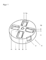
- FIGS. 1 and 2 show a support member 10, which has a substantially planar top surface 12 and a top surface 12 substantially perpendicularly arranged cylindrical wall 14.
- the top surface 12 is formed in particular round.
- a locking edge 15 is arranged on the inside of the wall 14, which is in particular formed circumferentially.
- a passage opening 18 is arranged centrally.
- a plurality in the present case four resilient elements 16 are arranged.
- the resilient elements 16 are arranged in particular at the same angular distance from each other.
- the resilient elements 16 are formed as leaf spring-like elements with a first end 16a and a second end 16b.
- the spring-like resilient elements 16 are arranged with their second end 16 b on the top surface 12 and in particular arranged integrally on the top surface 12.
- the first end 16a of the resilient elements 16 is thus a free end of the resilient elements 16.
- the leaf spring-like resilient elements 16 are arranged at an angle to the plane of the top surface 12 and protrude with its free first end 16a in the interior of the support member 10.
- the leaf spring-like resilient elements 16 are in particular rectangular and arranged such that the longitudinal axis of the rectangular resilient elements 16 are aligned in the radial direction on the circular top surface 12.
- the resilient elements 16 are arranged in particular in a respective recess 20 in the top surface 12.
- the recesses 20 are approximately rectangular and arranged with their longitudinal axis in the radial direction in the top surface 12.
- the mounting part 10 can be produced by injection molding, wherein in particular the resilient elements 16 are integrally arranged on the top surface 12.
- FIG. 3 shows a longitudinal section through the support member 10 according to the FIGS. 1 and 2 im in a chair leg 40 inserted state.
- the support member 10 can be pressed into the cavity in the chair leg 40, inserted, glued, screwed or clamped, as in FIG. 3 shown.
- the support member 10 can be secured in a recess of the chair leg 40 or under the chair leg 40 with a screw or the like, which is guided through the passage opening 18 and screwed into the chair leg 40.
- the support member 10 may be inserted into a non-illustrated receiving part on the chair leg 40, which may be formed for example as a vibration damping element.
- an insert 30 can be used, which is formed substantially cylindrical with a first end face 30a and an opposite second end face 30b.
- the first end face 30a is formed as a first ground contact layer 32, while the second end face 30b may have a second ground contact layer 34.
- the first ground contacting layer 32 may be made of various materials such as felt, plastic, rubber, metal, porcelain, elastic materials or lubricious materials to accommodate various floor coverings. If two bottom contact layers 32, 34 are arranged on the insert 30, these are preferably made of different materials in order to be used as a turning insert when using the corresponding furniture part on different floor coverings.
- the insert 30 has on its cylindrical outer wall on a locking edge 36, which is preferably formed circumferentially.
- the insert 30 is inserted into the mounting part 10, wherein the locking edge 36 of the insert 30 is pushed over the locking edge 15 of the wall 14 of the support member 10 and locked in the insertion direction behind it.
- the insert 30 is rotatable in the holding part 10, in particular about an axis A which corresponds to the longitudinal axis, in particular the axis of rotation, of the cylindrical wall 14 of the holding part 10, relative to the holding part 10. This is promoted in particular by the fact that both the locking edge 36 and the locking edge 15 are formed circumferentially.
- the insert 30 has a height h.
- the latching edge 36 of the insert 30 is arranged at a distance d from the second end face 30b of the insert 30. If both a first ground contact layer 32 and a second ground contact layer 34 are formed on the insert 30, the locking edge 36 is arranged approximately at half the height h.
- the distance d of the latching edge 36 to the second end face 30b is matched to the height of the wall 14 and the distance between the free first ends 16a of the resilient elements 16 to the top surface 12, which is used in inserted into the support member 10 insert 30, the free first ends 16a abut the resilient elements 16 on the second end face 30 b of the insert 30, if appropriate, rest under low bias.
- the insert 30 can be pressed against the force of the resilient elements 16 in the support member 10 in the axial direction along the axis A relative to the support member 10 in the support member 10, but also diametrically through the use 30 extending axes, in particular horizontal axes in which support member 10 are tilted to accommodate unevenness in the ground.
- the support member 10 may have in the wall 14 a recess 13 which in particular adjacent to the top surface 18, and through which a release tool, such as a screwdriver, can be inserted from the outside into the support member 10 to the arranged in the support member 10 insert 30th lever out or push out.
- a release tool such as a screwdriver
Landscapes
- Legs For Furniture In General (AREA)
Abstract
Description
- Die Erfindung betrifft ein Halterungsteil zur Befestigung an Möbelstücken, insbesondere an Möbelfüßen, gemäß dem Oberbegriff des Patentanspruchs 1.
- Bekannt sind Halterungsteile zur Befestigung an Möbelstücken, insbesondere an Möbelfüßen, in welchen ein Einsatz, welcher auf einer ersten Seite eine erste Bodenkontaktschicht aufweist, befestigbar ist. Die Halterungsteile werden entweder direkt an den Möbelstücken befestigt oder in ein an dem Möbelstück angeordnetes Aufnahmeteil eingesetzt. Die Bodenkontaktschicht des Einsatzes kann an dem entsprechenden Bodenbelag angepasst sein und insbesondere lösbar in dem Halterungsteil befestigbar sein, um ein einfaches Auswechseln zu ermöglichen. Bekannt ist es, die Einsätze in dem Halterungsteil über eine Rastverbindung zu befestigen, um ein einfaches Auswechseln zu ermöglichen.
- Die Aufgabe der Erfindung besteht darin, ein Halterungsteil zur Befestigung an Möbelstücken weiter zu verbessern, insbesondere derart, dass ein erhöhter Komfort geboten wird und/oder die Handhabung der Halterungsteile vereinfacht wird.
- Die Aufgabe wird erfindungsgemäß gelöst durch ein Halterungsteil mit den Merkmalen des Patentanspruchs 1.
- Vorteilhafte Ausgestaltungen und Weiterbildungen der Erfindung sind in den abhängigen Ansprüchen angegeben.
- Das erfindungsgemäße Halterungsteil zur Befestigung an Möbelstücken, insbesondere an Möbelfüßen, in welchem ein Einsatz, welcher auf einer ersten Seite eine erste Bodenkontaktschicht aufweist, befestigbar ist, zeichnet sich dadurch aus, dass das Halterungsteil eine Deckfläche aufweist, in welcher wenigstens ein federndes Element angeordnet ist. Bei in dem Halterungsteil eingesetztem Einsatz beaufschlagt das wenigstens eine Federelement den Einsatz, wobei eine Bewegung des Einsatzes gegen die Federkraft des federnden Elements möglich ist. Dadurch kann sich der Einsatz in dem Halterungsteil relativ zu dem Halterungsteil bewegen, wodurch sich der Einsatz in seiner relativen Position zu dem Halterungsteil an Unebenheiten der Bodenfläche anpassen kann.
- Gemäß einer bevorzugten Ausführungsform der Erfindung sind an der Deckfläche mehrere federnde Elemente, insbesondere zwei bis sechs federnde Elemente, vorzugsweise vier federnde Elemente angeordnet, um einerseits eine Kippbewegung des Einsatzes in dem Halterungsteil um beliebige horizontale Achsen zu ermöglichen und andererseits eine ausreichende Stabilität der Position des Einsatzes in dem Halterungsteil gewährleisten zu können.
- Gemäß einer besonders bevorzugten Ausführungsform der Erfindung sind die federnden Elemente einstückig an der Deckfläche angeordnet, um ein einfaches und kostengünstiges Herstellungsverfahren, beispielsweise im Spritzgussverfahren, zu ermöglichen.
- Vorzugsweise sind die federnden Elemente als blattfederartige Elemente ausgebildet, welche besonders einfach hergestellt und insbesondere kostengünstig und einfach im Spritzgussverfahren gefertigt werden können.
- Vorzugsweise sind die federartigen Elemente in radialer Richtung an der Deckfläche angeordnet, um eine ausreichende Stabilität der Position des Einsatzes in dem Halterungsteil zu ermöglichen.
- Gemäß einer bevorzugten Ausführungsform der Erfindung weisen die blattfederartigen Elemente ein freies Ende auf, welches aus der Deckfläche in Richtung auf den zu befestigenden Einsatz hervorragt. Dadurch ergibt sich eine besonders platzsparende Anordnung der federnden Elemente.
- Gemäß einer besonders bevorzugten Ausführungsform der Erfindung ist der Einsatz lösbar befestigbar, insbesondere mittels einer Rastverbindung, um ein einfaches Auswechseln des Einsatzes, beispielsweise bei Abnutzung des Einsatzes oder bei Verwendung von Einsätzen mit verschiedenen Bodenkontaktschichten zur Verwendung auf verschiedenen Bodenbelägen zu ermöglichen.
- Gemäß einer vorteilhaften Ausführungsform der Erfindung ist an der Deckfläche eine zylindrische Wandung angeordnet, an welcher vorzugsweise eine auf der Innenseite der Wandung angeordnete, vorzugsweise umlaufend ausgebildete Rastkante angeordnet ist. Ein derartig ausgestaltetes Halterungsteil kann besonders einfach im Spritzgussverfahren hergestellt werden. Die Rastkante bietet eine einfache und kostengünstige Möglichkeit zur Herstellung einer Rastverbindung zwischen dem Halterungsteil und dem Einsatz.
- Vorzugsweise ermöglicht die Rastverbindung zwischen dem Halterungsteil und dem Einsatz eine Drehung des Einsatzes um eine Achse relativ zu dem Halterungsteil und/oder eine Bewegung des Einsatzes in Axialrichtung gegen die Federkraft des federnden Elementes entlang der Achse relativ zu dem Halterungsteil. Dadurch wird eine flexible Anpassung der Position des Einsatzes an Unebenheiten des Bodens relativ zur Position des Halterungsteils ermöglicht.
- Ein erfindungsgemäßer Untersetzer zur Befestigung an Möbelstücken, insbesondere Möbelfüßen, weist ein Halterungsteil gemäß einem der vorhergehenden Ansprüche auf, in welchem ein Einsatz, welcher auf einer ersten Seite eine erste Bodenkontaktschicht aufweist, befestigt ist.
- Die Erfindung wird anhand der nachfolgenden Figuren ausführlich erläutert. Es zeigen:
- Figur 1:
- eine perspektivische Ansicht eines Ausführungsbeispiels eines Halterungsteils gemäß der Erfindung,
- Figur 2:
- eine weitere perspektivische Ansicht des Halterungsteils gemäß
Figur 1 und - Figur 3:
- einen Längsschnitt durch das Halterungsteil gemäß
Figur 1 mit einem eingesetzten Einsatz und dem Halterungsteil in in ein Stuhlbein eingesetztem Zustand. - Die
Figuren 1 und2 zeigen ein Halterungsteil 10, welches eine im Wesentlichen ebene Deckfläche 12 und eine an der Deckfläche 12 im Wesentlichen senkrecht angeordnete zylindrische Wandung 14 aufweist. Die Deckfläche 12 ist insbesondere rund ausgebildet. An dem der Deckfläche 12 abgewandten Rand der Wandung 14 ist auf der Innenseite der Wandung 14 eine Rastkante 15 angeordnet, welche insbesondere umlaufend ausgebildet ist. - In der Deckfläche 12 ist zentrisch eine Durchgangsöffnung 18 angeordnet.
- In der Deckfläche 12 sind mehrere, vorliegend vier federnde Elemente 16 angeordnet. Die federnden Elemente 16 sind insbesondere im gleichen Winkelabstand zueinander angeordnet.
- Die federnden Elemente 16 sind als blattfederartige Elemente mit einem ersten Ende 16a und einem zweiten Ende 16b ausgebildet. Dabei sind die federartigen federnden Elemente 16 mit ihrem zweiten Ende 16b an der Deckfläche 12 angeordnet und insbesondere einstückig an der Deckfläche 12 angeordnet. Das erste Ende 16a der federnden Elemente 16 ist somit ein freies Ende der federnden Elemente 16. Wie insbesondere in
Figur 2 erkennbar, sind die blattfederartigen federnden Elemente 16 in einem Winkel zur Ebene der Deckfläche 12 angeordnet und ragen mit ihrem freien ersten Ende 16a in den Innenraum des Halterungsteils 10. Die blattfederartigen federnden Elemente 16 sind insbesondere rechteckig ausgebildet und derart angeordnet, dass die Längsachse der rechteckigen federnden Elemente 16 in radialer Richtung an der runden Deckfläche 12 ausgerichtet sind. - Die federnden Elemente 16 sind insbesondere in jeweils einer Ausnehmung 20 in der Deckfläche 12 angeordnet. Die Ausnehmungen 20 sind dabei etwa rechteckig ausgebildet und mit ihrer Längsachse in radialer Richtung in der Deckfläche 12 angeordnet.
- Das Halterungsteil 10 kann im Spritzgussverfahren hergestellt werden, wobei insbesondere die federnden Elemente 16 einstückig an der Deckfläche 12 angeordnet werden.
-
Figur 3 zeigt einen Längsschnitt durch das Halterungsteil 10 gemäß denFiguren 1 und2 im in ein Stuhlbein 40 eingesetzten Zustand. Das Halterungsteil 10 kann in den Hohlraum in dem Stuhlbein 40 eingepresst, eingesteckt, eingeklebt, eingeschraubt oder eingeklemmt werden, wie inFigur 3 dargestellt. Alternativ oder zusätzlich kann das Halterungsteil 10 in einer Ausnehmung des Stuhlbeins 40 oder unter dem Stuhlbein 40 mit einer Schraube oder Ähnlichem befestigt werden, welche durch die Durchgangsöffnung 18 geführt und in dem Stuhlbein 40 verschraubt wird. In einer weiteren alternativen Ausführungsform kann das Halterungsteil 10 in ein nicht dargestelltes Aufnahmeteil an dem Stuhlbein 40 eingesetzt werden, welches beispielsweise als schwingungsdämpfendes Element ausgebildet sein kann. - In das Halterungsteil 10 ist ein Einsatz 30 einsetzbar, welcher im Wesentlichen zylindrisch mit einer ersten Stirnseite 30a und einer gegenüberliegenden zweiten Stirnseite 30b ausgebildet ist. Die erste Stirnseite 30a ist als erste Bodenkontaktschicht 32 ausgebildet, während die zweite Stirnseite 30b eine zweite Bodenkontaktschicht 34 aufweisen kann. Die erste Bodenkontaktschicht 32 kann aus verschiedenen Materialien, wie beispielsweise Filz, Kunststoff, Gummi, Metall, Porzellan, elastischen Materialien oder gleitfähigen Materialien gefertigt sein, um verschiedenen Bodenbelägen Rechnung zu tragen. Falls an dem Einsatz 30 zwei Bodenkontaktschichten 32, 34 angeordnet sind, sind diese vorzugsweise aus verschiedenen Materialien gefertigt, um als Wendeeinsatz bei Benutzung des entsprechenden Möbelteils auf verschiedenen Bodenbelägen verwendet werden zu können.
- Der Einsatz 30 weist an seiner zylindrischen Außenwand eine Rastkante 36 auf, welche vorzugsweise umlaufend ausgebildet ist. Der Einsatz 30 wird in das Halterungsteil 10 eingesetzt, wobei die Rastkante 36 des Einsatzes 30 über die Rastkante 15 der Wandung 14 des Halterungsteils 10 geschoben wird und in Einschubrichtung dahinter verrastet. Der Einsatz 30 ist in dem Halterungsteil 10 insbesondere um eine Achse A, welche der Längsachse, insbesondere der Rotationsachse, der zylindrischen Wandung 14 des Halterungsteils 10 entspricht, relativ zu dem Halterungsteil 10 drehbar. Dies wird insbesondere dadurch begünstigt, dass sowohl die Rastkante 36 als auch die Rastkante 15 umlaufend ausgebildet sind.
- Der Einsatz 30 weist eine Höhe h auf. Die Rastkante 36 des Einsatzes 30 ist in einem Abstand d zur zweiten Stirnseite 30b des Einsatzes 30 angeordnet. Sind sowohl eine erste Bodenkontaktschicht 32 als auch eine zweite Bodenkontaktschicht 34 an dem Einsatz 30 ausgebildet, ist die Rastkante 36 etwa auf halber Höhe h angeordnet.
- Der Abstand d der Rastkante 36 zu der zweiten Stirnseite 30b ist derart auf die Höhe der Wandung 14 und den Abstand der freien ersten Enden 16a der federnden Elemente 16 zur Deckfläche 12 abgestimmt, das bei in das Halterungsteil 10 eingesetztem Einsatz 30 die freien ersten Enden 16a der federnden Elemente 16 an der zweiten Stirnseite 30 b des Einsatzes 30 anliegen, gegebenenfalls unter geringer Vorspannung anliegen. Wird der Stuhl mit dem Stuhlbein 40 auf einen Boden gestellt, welcher uneben ist, kann der Einsatz 30 gegen die Kraft der federnden Elemente 16 in dem Halterungsteil 10 in axialer Richtung entlang der Achse A relativ zu dem Halterungsteil 10 in das Halterungsteil 10 hereingedrückt werden, aber auch um diametral durch den Einsatz 30 verlaufende Achsen, insbesondere horizontale Achsen, in dem Halterungsteil 10 gekippt werden, um sich an Unebenheiten in dem Boden anzupassen.
- Das Halterungsteil 10 kann in der Wandung 14 eine Ausnehmung 13 aufweisen, welche insbesondere an die Deckfläche 18 angrenzt, und durch welche ein Löswerkzeug, beispielsweise ein Schraubendreher, von außen in das Halterungsteil 10 eingeführt werden kann, um den in dem Halterungsteil 10 angeordneten Einsatz 30 herauszuhebeln oder herauszudrücken.
-
- 10
- Halterungsteil
- 12
- Deckfläche
- 13
- Ausnehmung
- 14
- Wandung
- 15
- Rastkante
- 16
- federndes Element
- 16a
- erstes Ende
- 16b
- zweites Ende
- 18
- Durchgangsöffnung
- 20
- Ausnehmung
- 30
- Einsatz
- 30a
- erste Stirnseite
- 30b
- zweite Stirnseite
- 32
- erste Bodenkontaktschicht
- 34
- zweite Bodenkontaktschicht
- 36
- Rastkante
- 40
- Stuhlbein
- A
- Achse
- h
- Höhe
- d
- Abstand
Claims (10)
- Halterungsteil (10) zur Befestigung an Möbelstücken, insbesondere an Möbelfüßen, in welchem ein Einsatz (30), welcher auf einer ersten Stirnseite (30a) eine erste Bodenkontaktschicht (32) aufweist, befestigbar ist,
dadurch gekennzeichnet, dass das Halterungsteil (10) eine Deckfläche (12) aufweist, an welcher wenigstens ein federndes Element (16) angeordnet ist. - Halterungsteil nach einem der vorhergehenden Ansprüche,
dadurch gekennzeichnet, dass an der Deckfläche (12) mehrere federnde Elemente (16), insbesondere zwei bis sechs federnde Elemente (16), vorzugsweise vier federnde Elemente (16) angeordnet sind. - Halterungsteil nach einem der vorhergehenden Ansprüche,
dadurch gekennzeichnet, dass die federnden Elemente (16) einstückig an der Deckfläche (12) angeordnet sind. - Halterungsteil nach einem der vorhergehenden Ansprüche,
dadurch gekennzeichnet, dass die federnden Elemente (16) als blattfederartige Elemente ausgebildet sind. - Halterungsteil nach Anspruch 4,
dadurch gekennzeichnet, dass die blattfederartigen Elemente in radialer Richtung an der Deckfläche (12) angeordnet sind. - Halterungsteil nach Anspruch 4 oder 5,
dadurch gekennzeichnet, dass die blattfederartigen Elemente ein freies erstes Ende (16a) aufweisen, welches aus der Deckfläche in Richtung auf den zu befestigenden Einsatz (30) hervorragen. - Halterungsteil nach einem der vorhergehenden Ansprüche,
dadurch gekennzeichnet, dass der Einsatz (30) lösbar befestigbar ist, insbesondere mittels einer Rastverbindung (36, 15). - Halterungsteil nach einem der vorhergehenden Ansprüche,
dadurch gekennzeichnet, dass an der Deckfläche (12) eine zylindrische Wandung (14) angeordnet ist, an welcher vorzugsweise eine auf der Innenseite der Wandung angeordnete vorzugsweise umlaufend ausgebildete Rastkante (15) angeordnet ist. - Halterungsteil nach Anspruch 7 oder 8,
dadurch gekennzeichnet, dass die Rastverbindung (36, 15) zwischen dem Halterungsteil (10) und dem Einsatz (30) eine Drehung des Einsatzes (30) um eine Achse (A) relativ zu dem Halterungsteil (10) und/oder eine Bewegung des Einsatzes (30) in axialer Richtung gegen die Federkraft des federnden Elements (16) entlang der Achse (A) relativ zu dem Halterungsteil (10) ermöglicht. - Untersetzer zur Befestigung an Möbelstücken, insbesondere
Möbelfüßen, mit einem Halterungsteil (10) gemäß einem der vorhergehenden Ansprüche, in welchem ein Einsatz (30), welcher auf einer ersten Stirnseite (30a) eine erste Bodenkontaktschicht (32) aufweist, befestigt ist.
Priority Applications (2)
| Application Number | Priority Date | Filing Date | Title |
|---|---|---|---|
| PL11188933T PL2591702T3 (pl) | 2011-11-14 | 2011-11-14 | Część ustalająca do mocowania do mebli |
| EP11188933.3A EP2591702B1 (de) | 2011-11-14 | 2011-11-14 | Halterungsteil zur Befestigung an Möbelstücken |
Applications Claiming Priority (1)
| Application Number | Priority Date | Filing Date | Title |
|---|---|---|---|
| EP11188933.3A EP2591702B1 (de) | 2011-11-14 | 2011-11-14 | Halterungsteil zur Befestigung an Möbelstücken |
Publications (2)
| Publication Number | Publication Date |
|---|---|
| EP2591702A1 true EP2591702A1 (de) | 2013-05-15 |
| EP2591702B1 EP2591702B1 (de) | 2015-05-27 |
Family
ID=45062925
Family Applications (1)
| Application Number | Title | Priority Date | Filing Date |
|---|---|---|---|
| EP11188933.3A Active EP2591702B1 (de) | 2011-11-14 | 2011-11-14 | Halterungsteil zur Befestigung an Möbelstücken |
Country Status (2)
| Country | Link |
|---|---|
| EP (1) | EP2591702B1 (de) |
| PL (1) | PL2591702T3 (de) |
Cited By (1)
| Publication number | Priority date | Publication date | Assignee | Title |
|---|---|---|---|---|
| EP3011867A1 (de) * | 2014-10-23 | 2016-04-27 | Fermob | Endabdeckung für möbelstück |
Citations (3)
| Publication number | Priority date | Publication date | Assignee | Title |
|---|---|---|---|---|
| US1580781A (en) * | 1924-08-16 | 1926-04-13 | Gen Fireproofing Co | Foot for furniture legs |
| US20060231702A1 (en) * | 2005-04-05 | 2006-10-19 | Acp, Llc | Furniture Glide |
| FR2947440A1 (fr) * | 2009-07-02 | 2011-01-07 | Gpi | Patin de glissement destine a etre fixe sous des pieds de meubles ou similaires |
-
2011
- 2011-11-14 PL PL11188933T patent/PL2591702T3/pl unknown
- 2011-11-14 EP EP11188933.3A patent/EP2591702B1/de active Active
Patent Citations (3)
| Publication number | Priority date | Publication date | Assignee | Title |
|---|---|---|---|---|
| US1580781A (en) * | 1924-08-16 | 1926-04-13 | Gen Fireproofing Co | Foot for furniture legs |
| US20060231702A1 (en) * | 2005-04-05 | 2006-10-19 | Acp, Llc | Furniture Glide |
| FR2947440A1 (fr) * | 2009-07-02 | 2011-01-07 | Gpi | Patin de glissement destine a etre fixe sous des pieds de meubles ou similaires |
Cited By (2)
| Publication number | Priority date | Publication date | Assignee | Title |
|---|---|---|---|---|
| EP3011867A1 (de) * | 2014-10-23 | 2016-04-27 | Fermob | Endabdeckung für möbelstück |
| FR3027498A1 (fr) * | 2014-10-23 | 2016-04-29 | Fermob | Embout pour article mobilier |
Also Published As
| Publication number | Publication date |
|---|---|
| PL2591702T3 (pl) | 2015-10-30 |
| EP2591702B1 (de) | 2015-05-27 |
Similar Documents
| Publication | Publication Date | Title |
|---|---|---|
| EP1784318B1 (de) | Einbauvorrichtung für einen sensor | |
| EP4175512B1 (de) | Schublade mit einer haltevorrichtung zur halterung einer auf der schubladenseitenwand aufsetzbaren dekorplatte | |
| WO2016146272A1 (de) | Halteelement für einen tür- oder fensterdrücker und anordnung eines tür- oder fensterdrückers an einer aufnahmeöffnung eines fensterrahmens, eines türblatts oder dergleichen | |
| DE102012208084B3 (de) | Anlenk-Vorrichtung zum Anlenken eines Reibungs-Dämpfers an eine Waschmaschine | |
| EP2591702B1 (de) | Halterungsteil zur Befestigung an Möbelstücken | |
| DE202007008827U1 (de) | Vorrichtung mit einem Unterteil und einer Rückholfeder zur drehbaren Lagerung eines Ausstattungsteils, insbesondere eines Türdrückers | |
| DE102010032778A1 (de) | Vorrichtung zum Aufstecken auf einen Gewindebolzen | |
| EP2588766B1 (de) | Befestigungseinrichtung | |
| DE102016124327A1 (de) | Scheibeneinheit und Einlegeteil für eine Scheibeneinheit | |
| DE202020100611U1 (de) | Stützfuß | |
| EP1751437B1 (de) | Positionsmesseinrichtung | |
| DE202020100612U1 (de) | Stützfuß | |
| DE102013114247B4 (de) | Mit einem Möbelbeschlag ausgestattetes Möbelstück | |
| EP3543433B1 (de) | Zentrieranordnung für eine türgriffgarnitur und türgriffgarnitur mit einer solchen positionieranordnung | |
| EP1747941B1 (de) | Sensorhalterung zur Herstellung eines Sensors an einem Fahrzeugteil | |
| DE29701469U1 (de) | Verbindungselement aus Kunststoff | |
| DE202010006027U1 (de) | Abstützvorrichtung für Maschinenfüße | |
| EP1507684A1 (de) | Halteteil zur anbringung von metallrahmennetzen, insbesondere von kofferraumseitennetzen | |
| EP2048377B1 (de) | Vorrichtung zum Befestigen eines Anbauteiles an einem Trägerteil | |
| EP3045617B1 (de) | Rosette und anordnung eines tür- oder fensterdrückers und einer rosette an einer aufnahmeöffnung eines türblatts, eines fensterblatts oder dergleichen | |
| DE102020102243A1 (de) | Stützfuß | |
| DE202015009658U1 (de) | Windschildvorrichtung | |
| EP2499939A1 (de) | Einsatz für Untersetzer für Möbelstücke | |
| DE102019119157B4 (de) | Verfahren zur Montage eines eine federbasierte Rasthaptik aufweisenden Bedienelements sowie ein zugehöriges Bedienelement | |
| DE102005000972B4 (de) | Elektrische Steckverbinderhälfte |
Legal Events
| Date | Code | Title | Description |
|---|---|---|---|
| PUAI | Public reference made under article 153(3) epc to a published international application that has entered the european phase |
Free format text: ORIGINAL CODE: 0009012 |
|
| AK | Designated contracting states |
Kind code of ref document: A1 Designated state(s): AL AT BE BG CH CY CZ DE DK EE ES FI FR GB GR HR HU IE IS IT LI LT LU LV MC MK MT NL NO PL PT RO RS SE SI SK SM TR |
|
| AX | Request for extension of the european patent |
Extension state: BA ME |
|
| 17P | Request for examination filed |
Effective date: 20131113 |
|
| RBV | Designated contracting states (corrected) |
Designated state(s): AL AT BE BG CH CY CZ DE DK EE ES FI FR GB GR HR HU IE IS IT LI LT LU LV MC MK MT NL NO PL PT RO RS SE SI SK SM TR |
|
| GRAP | Despatch of communication of intention to grant a patent |
Free format text: ORIGINAL CODE: EPIDOSNIGR1 |
|
| INTG | Intention to grant announced |
Effective date: 20150218 |
|
| GRAS | Grant fee paid |
Free format text: ORIGINAL CODE: EPIDOSNIGR3 |
|
| GRAA | (expected) grant |
Free format text: ORIGINAL CODE: 0009210 |
|
| AK | Designated contracting states |
Kind code of ref document: B1 Designated state(s): AL AT BE BG CH CY CZ DE DK EE ES FI FR GB GR HR HU IE IS IT LI LT LU LV MC MK MT NL NO PL PT RO RS SE SI SK SM TR |
|
| REG | Reference to a national code |
Ref country code: GB Ref legal event code: FG4D Free format text: NOT ENGLISH |
|
| REG | Reference to a national code |
Ref country code: CH Ref legal event code: EP |
|
| REG | Reference to a national code |
Ref country code: AT Ref legal event code: REF Ref document number: 728363 Country of ref document: AT Kind code of ref document: T Effective date: 20150615 |
|
| REG | Reference to a national code |
Ref country code: IE Ref legal event code: FG4D Free format text: LANGUAGE OF EP DOCUMENT: GERMAN |
|
| REG | Reference to a national code |
Ref country code: DE Ref legal event code: R096 Ref document number: 502011006934 Country of ref document: DE Effective date: 20150702 |
|
| REG | Reference to a national code |
Ref country code: RO Ref legal event code: EPE |
|
| REG | Reference to a national code |
Ref country code: LT Ref legal event code: MG4D |
|
| PG25 | Lapsed in a contracting state [announced via postgrant information from national office to epo] |
Ref country code: ES Free format text: LAPSE BECAUSE OF FAILURE TO SUBMIT A TRANSLATION OF THE DESCRIPTION OR TO PAY THE FEE WITHIN THE PRESCRIBED TIME-LIMIT Effective date: 20150527 Ref country code: FI Free format text: LAPSE BECAUSE OF FAILURE TO SUBMIT A TRANSLATION OF THE DESCRIPTION OR TO PAY THE FEE WITHIN THE PRESCRIBED TIME-LIMIT Effective date: 20150527 Ref country code: LT Free format text: LAPSE BECAUSE OF FAILURE TO SUBMIT A TRANSLATION OF THE DESCRIPTION OR TO PAY THE FEE WITHIN THE PRESCRIBED TIME-LIMIT Effective date: 20150527 Ref country code: NO Free format text: LAPSE BECAUSE OF FAILURE TO SUBMIT A TRANSLATION OF THE DESCRIPTION OR TO PAY THE FEE WITHIN THE PRESCRIBED TIME-LIMIT Effective date: 20150827 Ref country code: HR Free format text: LAPSE BECAUSE OF FAILURE TO SUBMIT A TRANSLATION OF THE DESCRIPTION OR TO PAY THE FEE WITHIN THE PRESCRIBED TIME-LIMIT Effective date: 20150527 Ref country code: PT Free format text: LAPSE BECAUSE OF FAILURE TO SUBMIT A TRANSLATION OF THE DESCRIPTION OR TO PAY THE FEE WITHIN THE PRESCRIBED TIME-LIMIT Effective date: 20150928 |
|
| REG | Reference to a national code |
Ref country code: PL Ref legal event code: T3 |
|
| REG | Reference to a national code |
Ref country code: NL Ref legal event code: MP Effective date: 20150527 |
|
| PG25 | Lapsed in a contracting state [announced via postgrant information from national office to epo] |
Ref country code: LV Free format text: LAPSE BECAUSE OF FAILURE TO SUBMIT A TRANSLATION OF THE DESCRIPTION OR TO PAY THE FEE WITHIN THE PRESCRIBED TIME-LIMIT Effective date: 20150527 Ref country code: GR Free format text: LAPSE BECAUSE OF FAILURE TO SUBMIT A TRANSLATION OF THE DESCRIPTION OR TO PAY THE FEE WITHIN THE PRESCRIBED TIME-LIMIT Effective date: 20150828 Ref country code: BG Free format text: LAPSE BECAUSE OF FAILURE TO SUBMIT A TRANSLATION OF THE DESCRIPTION OR TO PAY THE FEE WITHIN THE PRESCRIBED TIME-LIMIT Effective date: 20150827 Ref country code: IS Free format text: LAPSE BECAUSE OF FAILURE TO SUBMIT A TRANSLATION OF THE DESCRIPTION OR TO PAY THE FEE WITHIN THE PRESCRIBED TIME-LIMIT Effective date: 20150927 Ref country code: RS Free format text: LAPSE BECAUSE OF FAILURE TO SUBMIT A TRANSLATION OF THE DESCRIPTION OR TO PAY THE FEE WITHIN THE PRESCRIBED TIME-LIMIT Effective date: 20150527 |
|
| PG25 | Lapsed in a contracting state [announced via postgrant information from national office to epo] |
Ref country code: EE Free format text: LAPSE BECAUSE OF FAILURE TO SUBMIT A TRANSLATION OF THE DESCRIPTION OR TO PAY THE FEE WITHIN THE PRESCRIBED TIME-LIMIT Effective date: 20150527 Ref country code: DK Free format text: LAPSE BECAUSE OF FAILURE TO SUBMIT A TRANSLATION OF THE DESCRIPTION OR TO PAY THE FEE WITHIN THE PRESCRIBED TIME-LIMIT Effective date: 20150527 |
|
| PG25 | Lapsed in a contracting state [announced via postgrant information from national office to epo] |
Ref country code: SK Free format text: LAPSE BECAUSE OF FAILURE TO SUBMIT A TRANSLATION OF THE DESCRIPTION OR TO PAY THE FEE WITHIN THE PRESCRIBED TIME-LIMIT Effective date: 20150527 Ref country code: CZ Free format text: LAPSE BECAUSE OF FAILURE TO SUBMIT A TRANSLATION OF THE DESCRIPTION OR TO PAY THE FEE WITHIN THE PRESCRIBED TIME-LIMIT Effective date: 20150527 |
|
| REG | Reference to a national code |
Ref country code: DE Ref legal event code: R097 Ref document number: 502011006934 Country of ref document: DE |
|
| PLBE | No opposition filed within time limit |
Free format text: ORIGINAL CODE: 0009261 |
|
| STAA | Information on the status of an ep patent application or granted ep patent |
Free format text: STATUS: NO OPPOSITION FILED WITHIN TIME LIMIT |
|
| PG25 | Lapsed in a contracting state [announced via postgrant information from national office to epo] |
Ref country code: IT Free format text: LAPSE BECAUSE OF FAILURE TO SUBMIT A TRANSLATION OF THE DESCRIPTION OR TO PAY THE FEE WITHIN THE PRESCRIBED TIME-LIMIT Effective date: 20150527 |
|
| 26N | No opposition filed |
Effective date: 20160301 |
|
| PG25 | Lapsed in a contracting state [announced via postgrant information from national office to epo] |
Ref country code: SI Free format text: LAPSE BECAUSE OF FAILURE TO SUBMIT A TRANSLATION OF THE DESCRIPTION OR TO PAY THE FEE WITHIN THE PRESCRIBED TIME-LIMIT Effective date: 20150527 |
|
| PG25 | Lapsed in a contracting state [announced via postgrant information from national office to epo] |
Ref country code: LU Free format text: LAPSE BECAUSE OF FAILURE TO SUBMIT A TRANSLATION OF THE DESCRIPTION OR TO PAY THE FEE WITHIN THE PRESCRIBED TIME-LIMIT Effective date: 20151114 Ref country code: MC Free format text: LAPSE BECAUSE OF FAILURE TO SUBMIT A TRANSLATION OF THE DESCRIPTION OR TO PAY THE FEE WITHIN THE PRESCRIBED TIME-LIMIT Effective date: 20150527 |
|
| REG | Reference to a national code |
Ref country code: CH Ref legal event code: PL |
|
| GBPC | Gb: european patent ceased through non-payment of renewal fee |
Effective date: 20151114 |
|
| PG25 | Lapsed in a contracting state [announced via postgrant information from national office to epo] |
Ref country code: LI Free format text: LAPSE BECAUSE OF NON-PAYMENT OF DUE FEES Effective date: 20151130 Ref country code: CH Free format text: LAPSE BECAUSE OF NON-PAYMENT OF DUE FEES Effective date: 20151130 |
|
| REG | Reference to a national code |
Ref country code: IE Ref legal event code: MM4A |
|
| REG | Reference to a national code |
Ref country code: FR Ref legal event code: ST Effective date: 20160729 |
|
| PG25 | Lapsed in a contracting state [announced via postgrant information from national office to epo] |
Ref country code: GB Free format text: LAPSE BECAUSE OF NON-PAYMENT OF DUE FEES Effective date: 20151114 Ref country code: IE Free format text: LAPSE BECAUSE OF NON-PAYMENT OF DUE FEES Effective date: 20151114 |
|
| PG25 | Lapsed in a contracting state [announced via postgrant information from national office to epo] |
Ref country code: FR Free format text: LAPSE BECAUSE OF NON-PAYMENT OF DUE FEES Effective date: 20151130 |
|
| PG25 | Lapsed in a contracting state [announced via postgrant information from national office to epo] |
Ref country code: HU Free format text: LAPSE BECAUSE OF FAILURE TO SUBMIT A TRANSLATION OF THE DESCRIPTION OR TO PAY THE FEE WITHIN THE PRESCRIBED TIME-LIMIT; INVALID AB INITIO Effective date: 20111114 Ref country code: SM Free format text: LAPSE BECAUSE OF FAILURE TO SUBMIT A TRANSLATION OF THE DESCRIPTION OR TO PAY THE FEE WITHIN THE PRESCRIBED TIME-LIMIT Effective date: 20150527 |
|
| PG25 | Lapsed in a contracting state [announced via postgrant information from national office to epo] |
Ref country code: SE Free format text: LAPSE BECAUSE OF FAILURE TO SUBMIT A TRANSLATION OF THE DESCRIPTION OR TO PAY THE FEE WITHIN THE PRESCRIBED TIME-LIMIT Effective date: 20150527 Ref country code: CY Free format text: LAPSE BECAUSE OF FAILURE TO SUBMIT A TRANSLATION OF THE DESCRIPTION OR TO PAY THE FEE WITHIN THE PRESCRIBED TIME-LIMIT Effective date: 20150527 Ref country code: NL Free format text: LAPSE BECAUSE OF FAILURE TO SUBMIT A TRANSLATION OF THE DESCRIPTION OR TO PAY THE FEE WITHIN THE PRESCRIBED TIME-LIMIT Effective date: 20150527 |
|
| PG25 | Lapsed in a contracting state [announced via postgrant information from national office to epo] |
Ref country code: BE Free format text: LAPSE BECAUSE OF NON-PAYMENT OF DUE FEES Effective date: 20151130 |
|
| PG25 | Lapsed in a contracting state [announced via postgrant information from national office to epo] |
Ref country code: MT Free format text: LAPSE BECAUSE OF FAILURE TO SUBMIT A TRANSLATION OF THE DESCRIPTION OR TO PAY THE FEE WITHIN THE PRESCRIBED TIME-LIMIT Effective date: 20150527 |
|
| PG25 | Lapsed in a contracting state [announced via postgrant information from national office to epo] |
Ref country code: TR Free format text: LAPSE BECAUSE OF FAILURE TO SUBMIT A TRANSLATION OF THE DESCRIPTION OR TO PAY THE FEE WITHIN THE PRESCRIBED TIME-LIMIT Effective date: 20150527 Ref country code: MK Free format text: LAPSE BECAUSE OF FAILURE TO SUBMIT A TRANSLATION OF THE DESCRIPTION OR TO PAY THE FEE WITHIN THE PRESCRIBED TIME-LIMIT Effective date: 20150527 |
|
| PG25 | Lapsed in a contracting state [announced via postgrant information from national office to epo] |
Ref country code: AL Free format text: LAPSE BECAUSE OF FAILURE TO SUBMIT A TRANSLATION OF THE DESCRIPTION OR TO PAY THE FEE WITHIN THE PRESCRIBED TIME-LIMIT Effective date: 20150527 |
|
| PGFP | Annual fee paid to national office [announced via postgrant information from national office to epo] |
Ref country code: RO Payment date: 20221108 Year of fee payment: 12 |
|
| PGFP | Annual fee paid to national office [announced via postgrant information from national office to epo] |
Ref country code: PL Payment date: 20221020 Year of fee payment: 12 |
|
| PG25 | Lapsed in a contracting state [announced via postgrant information from national office to epo] |
Ref country code: RO Free format text: LAPSE BECAUSE OF NON-PAYMENT OF DUE FEES Effective date: 20231114 |
|
| PG25 | Lapsed in a contracting state [announced via postgrant information from national office to epo] |
Ref country code: PL Free format text: LAPSE BECAUSE OF NON-PAYMENT OF DUE FEES Effective date: 20231114 |
|
| PGFP | Annual fee paid to national office [announced via postgrant information from national office to epo] |
Ref country code: AT Payment date: 20251117 Year of fee payment: 15 |
|
| PGFP | Annual fee paid to national office [announced via postgrant information from national office to epo] |
Ref country code: DE Payment date: 20251218 Year of fee payment: 15 |