EP2592182B1 - Lave-linge avec détrempage réduit et procédé de fonctionnement de celui-ci - Google Patents
Lave-linge avec détrempage réduit et procédé de fonctionnement de celui-ci Download PDFInfo
- Publication number
- EP2592182B1 EP2592182B1 EP12191352.9A EP12191352A EP2592182B1 EP 2592182 B1 EP2592182 B1 EP 2592182B1 EP 12191352 A EP12191352 A EP 12191352A EP 2592182 B1 EP2592182 B1 EP 2592182B1
- Authority
- EP
- European Patent Office
- Prior art keywords
- drum
- washing machine
- outer tub
- tub wall
- structures
- Prior art date
- Legal status (The legal status is an assumption and is not a legal conclusion. Google has not performed a legal analysis and makes no representation as to the accuracy of the status listed.)
- Not-in-force
Links
- 238000005406 washing Methods 0.000 title claims description 66
- 238000000034 method Methods 0.000 title claims description 15
- XLYOFNOQVPJJNP-UHFFFAOYSA-N water Substances O XLYOFNOQVPJJNP-UHFFFAOYSA-N 0.000 claims description 43
- 230000000295 complement effect Effects 0.000 claims description 2
- 238000003466 welding Methods 0.000 claims description 2
- 238000009987 spinning Methods 0.000 description 8
- 101150114468 TUB1 gene Proteins 0.000 description 7
- 230000000694 effects Effects 0.000 description 6
- 241000722921 Tulipa gesneriana Species 0.000 description 5
- 241000446313 Lamella Species 0.000 description 4
- 239000002184 metal Substances 0.000 description 4
- 239000011324 bead Substances 0.000 description 3
- 230000015572 biosynthetic process Effects 0.000 description 3
- 238000001035 drying Methods 0.000 description 3
- 238000005755 formation reaction Methods 0.000 description 3
- 238000005086 pumping Methods 0.000 description 3
- 230000009467 reduction Effects 0.000 description 3
- 238000009736 wetting Methods 0.000 description 3
- 230000001133 acceleration Effects 0.000 description 2
- 230000008901 benefit Effects 0.000 description 2
- 230000001419 dependent effect Effects 0.000 description 2
- 239000011521 glass Substances 0.000 description 2
- 239000007788 liquid Substances 0.000 description 2
- 238000004519 manufacturing process Methods 0.000 description 2
- 230000002093 peripheral effect Effects 0.000 description 2
- 230000004888 barrier function Effects 0.000 description 1
- 238000005452 bending Methods 0.000 description 1
- 244000309464 bull Species 0.000 description 1
- 230000006835 compression Effects 0.000 description 1
- 238000007906 compression Methods 0.000 description 1
- 238000010276 construction Methods 0.000 description 1
- 239000003599 detergent Substances 0.000 description 1
- 238000009826 distribution Methods 0.000 description 1
- 230000007613 environmental effect Effects 0.000 description 1
- 239000002979 fabric softener Substances 0.000 description 1
- 239000012530 fluid Substances 0.000 description 1
- 230000003993 interaction Effects 0.000 description 1
- 238000000465 moulding Methods 0.000 description 1
- 230000008569 process Effects 0.000 description 1
- 230000002035 prolonged effect Effects 0.000 description 1
- 230000004044 response Effects 0.000 description 1
- 238000000926 separation method Methods 0.000 description 1
- 239000007921 spray Substances 0.000 description 1
Images


Classifications
-
- D—TEXTILES; PAPER
- D06—TREATMENT OF TEXTILES OR THE LIKE; LAUNDERING; FLEXIBLE MATERIALS NOT OTHERWISE PROVIDED FOR
- D06F—LAUNDERING, DRYING, IRONING, PRESSING OR FOLDING TEXTILE ARTICLES
- D06F37/00—Details specific to washing machines covered by groups D06F21/00 - D06F25/00
- D06F37/02—Rotary receptacles, e.g. drums
- D06F37/04—Rotary receptacles, e.g. drums adapted for rotation or oscillation about a horizontal or inclined axis
Definitions
- the invention relates to a washing machine with reduced rewetting and a preferred method for its operation.
- the invention relates to a washing machine for the treatment of laundry with a program control, a water supply system, a rotatably mounted drum in a tub and a drive motor for the drum, wherein structures on the drum and / or in the tub influence the air flow, and a particularly suitable method to operate this washing machine (see DE-20 2009 000376 U ).
- a washing program generally has a rinsing phase with several spinning steps after a wetting phase and a washing phase.
- the centrifugal force forces the water from the laundry through drainage holes of the drum to the outside into a space between the drum and the tub, where it ideally flows into a lower part of the tub, a region comprising a heater, also referred to as a "heater bag" , From the radiator pocket, this water can then be pumped out for disposal or reuse.
- a heater also referred to as a "heater bag”
- the drum thus gives due to their rapid rotation of the amount of air, which is located in the space between the drum and tub, a tangential pulse in the direction of rotation of the drum.
- a tangential pulse in the direction of rotation of the drum.
- the water exiting through the perforated drum also leaves the drum in the tangential direction, i. In tangential direction, there is an additional, dependent on the actual water flow contribution to the tangential pulse.
- a circular circulation of the amount of air is obtained in the space between the drum and tub, which affects a forming on the inner wall of the tub water ring.
- a certain amount of water instead of being landed in the radiator pocket for pumping, is circulated on the inside of the tub (also referred to herein as the "side tub wall") as a so-called water ring.
- Known measures for deriving this water ring and thus to reduce the re-wetting are introduced into the tub form elements.
- This air flow entrains water droplets, for example from the surface of the water ring, so that the water ring is more like a wild spray than a compact amount of water and thus has a correspondingly large surface area.
- water droplets are in particular entrained from the water in the radiator bag. This effect is more pronounced when due to uneven, i. unbalanced, rotation of the drum, which may arise, for example, by an uneven distribution of the laundry in the drum, water droplets are thrown from the radiator pocket.
- the water droplets are drawn perpendicular to the air flow according to the velocity gradient in the flow (Bernoulli or Venturi effect) and thereby entrained in the longitudinal direction with the flow.
- the water droplets entrained with the air flow can in particular pass back to the laundry via the drum gap and thus bring about rewetting of the laundry, which thus has an increased residual moisture content.
- a disproportionate time and energy-consuming spin would be required, especially as the amount of water still in the system is progressively withdrawn slowly as the spin progresses.
- the EP 1 050 616 A1 describes a method for spinning in a washing machine, in which the reduction of the speed (“Abtouren”) after the spin is not carried out with high negative acceleration, but the steepness of the Abtourrampe is reduced, to avoid that the water ring coincides during Abtouren and dripping on the drum. A rewetting by the amount of water during the Skidding passes through the described air flow over the drum gap on the laundry, this is not avoided.
- the DE 197 52 512 A1 describes a washing machine with a washing tub rotatably arranged in a tub around a horizontal axis, wherein in the washing drum shell outwardly or inwardly directed formations are present.
- the DE 10 2005 026 175 A1 describes a water-leading household appliance, such as a washing machine, with a rotatably mounted laundry drum with a drum shell and at least one drum top surface, wherein imprints are applied to the laundry drum, wherein the edges of the embossments are formed elliptical.
- a washing drum for a washing machine which is provided via a cylindrical shell with a plurality of holes for the passage of working fluid. Between these holes trough-like characteristics or elevations are provided.
- the DE 102 05 306 A1 describes a drum washing machine with a laundry drum whose shell is perforated, and which is surrounded by a container within which it is mounted on its rear wall at least horizontally flying, and with a working section for spin-drying the laundry located in the drum.
- this drum type washing machine provision is made for substantially no air to flow from the container through the interior of the drum and back to the container during spin-drying.
- a precaution for example, is a barrier disposed in the annular gap between the charging opening of the drum and the front opening of the container.
- another measure is that the drum shell on a ring section, which is attached to the rear wall of the drum adjoins, at least a smaller specific hole area portion than on the closer to the feed opening arranged ring section.
- the DE 20 2009 000 376 U1 describes a washing drum for a washing machine, the cylindrical shell has a plurality of flow holes and attached to the outer side of the washing drum compression space paddles.
- the blades When spinning after the rinse and pumping out the rinsing liquid, the blades generate a negative pressure due to their wedge shape, so that the moisture in the laundry is exposed not only to the centrifugal forces but also this negative pressure.
- the object of the present invention was to provide a washing machine in which the treated laundry has a reduced residual moisture after spinning.
- the invention has for its object to provide a method for operating this washing machine.
- the invention thus relates to a washing machine for the treatment of laundry with a program control, a water supply system, a rotatably mounted drum in a tub and a drive motor for the drum wherein on a drum surface and / or a side tub wall in a space between the drum and the tub outwardly projecting structures are arranged, which generate upon rotation of the drum about a substantially horizontal axis of rotation directed towards a rear suds container wall axial air flow, with protruding structures are those which from the Surface of the drum or the side tub wall protrude into the space.
- the protruding structures on the drum surface and / or the side tub wall have an incline with respect to the axis of rotation of the drum increasing from the back tub wall toward the door of the washing machine.
- the term "generating a directed toward a rear tub wall air flow” is interpreted broad and includes in particular directed toward a rear tub wall axial air flow component, which counteracts a usually directed forward to the door of the washing machine axial air flow component.
- a reduced axial flow in the direction of the door is obtained, a quiescent state when both components cancel, or an axial air flow directed towards the rear suds container wall.
- no axial air flow occurs in the direction of the door of the washing machine more.
- the protruding structures form a helical structure.
- the protruding structures are lamellas, in particular helically arranged lamellae.
- the term "fin” herein generally refers to thin, long slices or leaves which may be flat or tortuous.
- the protruding structures are regularly arranged in a ring around the drum surface.
- a plurality of rings of protruding structures can be used.
- the protruding structures eg lamellas, are preferably larger or provided with a greater pitch of the structures than in a rear area of the drum surface.
- the protruding structures are disposed in a front half of the drum surface and / or a front half of the side tub wall.
- lamellas are arranged on the drum surface and on the lateral tub wall as outwardly projecting structures.
- the lamellae on the drum surface can be spaced axially and / or radially away from the lamellae on the lateral lye container wall.
- the protruding structures in particular lamellae, can differ from each other in their number, arrangement, shape and / or size. These are chosen as a function of the desired influence on the flow suitable.
- the protruding structures on the surface enhance radial air flow.
- the protruding structures are therefore chosen such that a radial flow around the drum is at least partially converted into an axial air flow directed towards the rear tub wall.
- a rotating air mass is then at least partially reshaped by the lamellae located on the inside of the tub, in particular the lateral tub wall, into an axial flow.
- the protruding structures in particular lamellae, on the drum surface and on the side tub wall wall in terms of number, arrangement, shape and / or size during the rotation of the drum in their influence on the air flow complement each other such that greater axial flow towards the rear tub wall results.
- the protruding structures in particular lamellae, on the drum surface and on the side tub wall wall in terms of number, arrangement, shape and / or size during the rotation of the drum in their influence on the air flow complement each other such that greater axial flow towards the rear tub wall results.
- a radial flow around the drum is converted into a flow directed towards the rear tub wall.
- protruding structures particularly lamellae
- their arrangement, size and number are generally similar.
- the direction of inclination of the structures on the drum surface is usually opposite to that on the side tub wall.
- beads are arranged on the drum surface as outwardly projecting structures.
- externally embossed helical beads can be incorporated into the drum.
- drainage holes are arranged on the drum surface with arranged obliquely to the axis of rotation of the drum tulips as protruding structures.
- the drainage holes can be suitably shaped for this purpose, eg elliptical.
- tulips are understood in particular to be outwardly directed collars, eg funnel-shaped collars. These can be shaped such that preferably tulips arranged helically on the drum surface be present and achieve a desired effect according to the invention in this way.
- these tulips can advantageously lie in the direction of lamellae also used on the drum surface.
- the tulips are preferably used as a supporting measure, e.g. together with lamellae on a side lye container wall.
- punched sheet metal parts can remain on one side of the drainage holes and be used as outwardly projecting structures in the context of the invention.
- a seam closing the drum can be designed as a spot weld with bent sheet metal ends as structures projecting outwards.
- a drum is made by bending a sheet and welding the sheet ends together.
- Such a seam can be provided obliquely in the blank of the sheet, so that it runs in the finished drum helically on the drum surface.
- Such seams can also be incorporated several times, preferably three times, in the drum shell.
- additional protruding structures can be incorporated as a correspondingly shaped blind seam. These would be, for example, in the drum shell inflected ribs.
- the suds container wall in particular the lateral suds container wall, can be suitably structured in order to facilitate an outflow of the water located on it and / or to reduce the velocity of an air flow on its surface.
- the structuring of the tub interior side can be achieved by various protuberances or recesses or by the arrangement of at least one component on the tub wall. For example, grooves or beads would be conceivable as depressions.
- less drainage holes may be provided than in the middle, since in these areas the holes are highly permeable to air in all probability the middle of the drum when hurling the Wäschering the local drainage holes covered.
- the air circulation should be reduced overall.
- the drum gap can be narrowed, for example, by a suitable construction of the sleeve, wherein the drum gap is narrowed, in particular in the areas of the presumed remindbefeuchtungs inflow.
- the invention also relates to a method for operating a washing machine for the treatment of laundry with a program control, a water supply system, a drum rotatably mounted in a tub and a drive motor for the drum, wherein on a drum surface and / or a side tub wall in a space between the drum and the tub outwardly projecting structures are arranged which generate upon rotation of the drum about a substantially horizontal axis of rotation directed towards a rear tub wall axial air flow, with protruding structures are those which from the surface of the drum or the lateral LaugenITAerwand protrude into the intermediate space, and wherein the protruding structures on the drum surface and / or the side tub wall have a pitch, relative to the axis of rotation of the drum, which from the rear tub wall in Direction towards the door of the washing machine increases.
- the drum is operated in the last spin step at a speed above the compensation speed. That is, in particular, that the rotational speed is so high that an axial air flow is present in the direction of a rear tub wall.
- This can be reduced, for example, a reinforced re-wetting during the reduction of the rotational speed of the drum during Abtouren, since the air flow takes a long time axially towards a rear tub wall.
- the washing machine according to the invention has the advantage that the axial flow of the air, which is usually directed forward in the direction of the door of the washing machine, can be compensated. This makes it possible to return water to laundry in the drum, i. a rewetting, reduces and thus improves the residual moisture. In this way, the drying process of the laundry following the washing can be considerably shortened without the need for prolonging the spinning step. This is very advantageous for reasons of economy and environmental protection. As part of the air flow is eliminated, a saving of energy, a longer life of the engine and other machine components can be achieved. In addition, the operation of the washing machine with a lower required drive power, larger accelerations, especially in the higher speed range, and in embodiments also a reduction of flow noise is possible.
- the radial flow can be significantly reduced, so that the formation of a continuously moving in a circle water ring can be counteracted to the tub wall.
- the water produced during the spin phase can be better dissipated.
- a spin phase can be shortened in time. This also makes the components of the Washing machine (especially drive motor and bearings) spared and it is consumed less energy.
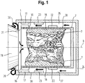
- Fig. 1 is a section through a first embodiment of a washing machine in the direction of the axis of rotation 3 of the drum 2 and thus shows a section through a side view.
- the tub 1 can be opened at the front by a door 19 with a bull's eye glass, which is sealed by a collar 20.
- first embodiment are on the drum surface 28 axially spaced from each other front slats 16 and rear slats 22 as protruding structures according to the invention arranged.
- front lamellae 17 counter blades with compared to the situation on the drum surface reversed slope
- rear slats 23 are arranged.
- the rear fins 22 and 23 are arranged on the side of the tub side wall 27 and the drum surface 28 that they can mesh with each other during a rotation of the drum 2.
- the combing effect is greater if - not shown here - the rear slats protrude more strongly into the intermediate space 26 between the tub 1 and drum 2 and there is a radial overlap between them.
- the front fins 16 and 17 on the side tub wall 27 and the drum surface 28, however, are opposed to each other.
- Fig. 1 shows the situation during spin, wherein the laundry 7 is applied as a laundry ring substantially the drum inside by the rotational movement of the drum 2 about its axis of rotation 3.
- a complex air flow is generated with a radial and an axial component, of which only the axial flow in the intermediate space 26 is shown here with arrows, which in the present case by a generated axial counterflow in the direction of the rear tub wall 24 at least reduced and is preferably compensated.
- This air flow circulates through the drainage holes 18 of the drum 2 according to the pressure equalization and passes through the drum gap 21 back into the interior of the drum 2, where entrained water droplets can hit the laundry and so contribute to the rewetting, if this flow is not counteracted according to the invention.
- first slats 16 are arranged in a front half 29 of the drum surface 28 and fins 17 and 23 in a front half of the side tub wall 27.
- Fig. 2 is a schematic representation of the presently relevant parts of a second embodiment of a washing machine.
- the washing machine has a tub 1, in which a drum 2 is rotatably mounted about a substantially horizontal axis of rotation 3 and can be operated by a drive motor 14. Wäschemit choir 4 and scooping devices 5 on the inner surface of the drum shell for example, a wash liquor 6 allow intensive washing of the laundry 7 with 6 or water wash.
- the washing machine also has a liquor inlet system, which includes a water connection fitting for the domestic water network 8, an electrically controllable valve 9 and a supply line 10 to the tub 1, which is guided via a dispenser 11, from the incoming water detergent can carry into the tub 1.
- a liquor inlet system which includes a water connection fitting for the domestic water network 8, an electrically controllable valve 9 and a supply line 10 to the tub 1, which is guided via a dispenser 11, from the incoming water detergent can carry into the tub 1.
- a heater 13 means a pump for the liquid contained in the tub 1 and the drum 2.
- Valve 9, Heater 13 and drive motor 14 may be controlled by a program controller 12 in response to a program schedule.
- FIG. 2 shown second embodiment of a washing machine are in the space 31 between the drum 2 and tub 1 on the drum surface 28 a total of four arranged as a helical in a ring slats 17 as protruding structures available. During a rotation of the drum, these generate an axial air flow in the direction of a rear suds container wall (not shown here in detail).
- the arrow indicates the direction of rotation of the drum 1 and thus the flow direction of the air.
- 25 means a radiator pocket in which centrifuged water is collected for pumping.
- FIG. 3 is a side view of a third embodiment of a washing machine shown.
- fins 16 are arranged in a front half 29 of the drum surface 28 and a front half 30 of the side tub wall 27.
- 19 means a door, 21 the drum gap and 24 the rear tub wall.
Landscapes
- Engineering & Computer Science (AREA)
- Textile Engineering (AREA)
- Main Body Construction Of Washing Machines And Laundry Dryers (AREA)
Claims (13)
- Lave-linge destiné au traitement de linge, comprenant une commande de programme (12), un système d'arrivée d'eau (8, 9, 10, 11), un tambour (2) logé de manière rotative dans une cuve de liquide de lavage (1), un moteur d'entraînement (14) pour le tambour (2), et comprenant des structures en saillie (16, 17, 22, 23), lesquelles sont disposées sur une surface de tambour (28) et/ou sur une paroi latérale (27) de la cuve de liquide de lavage, dans un espace intermédiaire (26) entre le tambour (2) et la cuve de liquide de lavage (1), les structures en saillie étant celles qui dépassent dans l'espace intermédiaire (26), hors de la surface du tambour (2), resp. de la paroi latérale (24) de la cuve de liquide de lavage, caractérisé en ce que les structures en saillie (16, 17, 22, 23), lors de la rotation du tambour (2) autour d'un axe de rotation (3) essentiellement horizontal, génèrent un flux d'air axial dirigé en direction d'une paroi arrière (24) de la cuve de liquide de lavage et en ce que les structures en saillie (16, 17, 22, 23) présentent sur la surface de tambour (28) et/ou sur la paroi latérale (27) de la cuve de lavage une pente par rapport à l'axe de rotation (3) du tambour (2), laquelle augmente de la paroi arrière (24) de la cuve de liquide de lavage en direction allant vers la porte (19) du lave-linge.
- Lave-linge selon la revendication 1, caractérisé en ce que les structures en saillie (16, 17, 22, 23) forment une structure hélicoïdale.
- Lave-linge selon la revendication 2, caractérisé en ce que les structures en saillie (16, 17, 22, 23) sont des lamelles disposées de manière hélicoïdale.
- Lave-linge selon l'une quelconque des revendications précédentes, caractérisé en ce que les structures en saillie (16, 17, 22, 23) sont disposées de manière régulière en une couronne autour de la surface de tambour (28).
- Lave-linge selon l'une quelconque des revendications précédentes, caractérisé en ce que les structures en saillie (16, 17, 22, 23) sont disposées dans une moitié avant (29) de la surface de tambour (28) et/ou dans une moitié avant (30) de la paroi latérale (27) de la cuve de liquide de lavage.
- Lave-linge selon l'une quelconque des revendications précédentes, caractérisé en ce que des lamelles sont disposées sur la surface de tambour (28) et sur la paroi latérale (27) de la cuve de liquide de lavage en tant que structures en saillie (16, 17, 22, 23).
- Lave-linge selon la revendication 6, caractérisé en ce que les lamelles (16, 17, 22, 23) situées sur la surface de tambour (28) sont axialement et/ou radialement distancées des lamelles situées sur la paroi latérale (27) de la cuve de liquide de lavage.
- Lave-linge selon l'une quelconque des revendications 6 et 7, caractérisé en ce que les lamelles sur la surface de tambour (28) et sur la paroi latérale (27) de la cuve de liquide de lavage se complètent, au point de vue quantité, disposition, forme et/ou taille, pendant la rotation du tambour (2) quant à leur influence sur le flux d'air de manière à ce qu'il en résulte un flux axial plus important en direction de la paroi arrière (24) de la cuve de liquide de lavage, les lamelles (16, 22) étant disposées en plusieurs couronnes autour de la surface de tambour (28) et, dans une couronne disposée plus près de la porte (19) du lave-linge sur la surface de tambour (28), les lamelles (16) étant plus grandes ou munies d'une pente plus importante des structures que dans une partie arrière de la surface de tambour (28).
- Lave-linge selon l'une quelconque des revendications précédentes, caractérisé en ce que des nervures sont disposées sur la surface de tambour (28) en tant que structures en saillie (16, 22).
- Lave-linge selon l'une quelconque des revendications précédentes, caractérisé en ce que des trous de drainage (18) munis de fourreaux disposés de manière inclinée par rapport à l'axe de rotation (3) du tambour (2) sont disposés en tant que structures en saillie (16, 22).
- Lave-linge selon l'une quelconque des revendications précédentes, caractérisé en ce qu'au moins une soudure fermant le tambour (2) est réalisée comme soudure par points comprenant des extrémités de tôle repliées en tant que structures en saillie (16,22).
- Procédé de fonctionnement d'un lave-linge destiné au traitement de linge, comprenant une commande de programme (12), un système d'arrivée d'eau (8, 9, 10, 11), un tambour (2) logé de manière rotative dans une cuve de liquide de lavage (1) et un moteur d'entraînement (14) pour le tambour (2), des structures en saillie (16, 17, 22, 23) étant disposées dans un espace intermédiaire (26) entre le tambour (2) et la cuve de liquide de lavage (1) sur une surface de tambour (28) et/ou sur une paroi latérale (27) de la cuve de liquide de lavage, les structures en saillie étant celles qui dépassent dans l'espace intermédiaire (26), hors de la surface du tambour (2), resp. de la paroi latérale (24) de la cuve de liquide de lavage,
caractérisé par une étape à laquelle le tambour (2) est tourné, les structures en saillie (16, 17, 22, 23), lors de la rotation du tambour (2) autour d'un axe de rotation (3) essentiellement horizontal, générant un flux d'air axial dirigé en direction d'une paroi arrière (24) de la cuve de liquide de lavage, les structures en saillie (16, 17, 22, 23) présentant sur la surface de tambour (28) et/ou sur la paroi latérale (27) de la cuve de lavage une pente par rapport à l'axe de rotation (3) du tambour (2), laquelle augmente de la paroi arrière (24) de la cuve de liquide de lavage en direction allant vers la porte (19) du lave-linge. - Procédé selon la revendication 12, caractérisé en ce que le tambour (2), à la dernière étape d'essorage, fonctionne avec une vitesse de rotation située au-delà d'une vitesse de compensation, la vitesse de compensation étant la vitesse de rotation du tambour (2) à laquelle il n'y a plus de flux d'air en direction axiale.
Applications Claiming Priority (1)
| Application Number | Priority Date | Filing Date | Title |
|---|---|---|---|
| DE102011086142A DE102011086142A1 (de) | 2011-11-11 | 2011-11-11 | Waschmaschine mit verringerter Rückbefeuchtung sowie Verfahren zu ihrem Betrieb |
Publications (2)
| Publication Number | Publication Date |
|---|---|
| EP2592182A1 EP2592182A1 (fr) | 2013-05-15 |
| EP2592182B1 true EP2592182B1 (fr) | 2018-02-21 |
Family
ID=47146226
Family Applications (1)
| Application Number | Title | Priority Date | Filing Date |
|---|---|---|---|
| EP12191352.9A Not-in-force EP2592182B1 (fr) | 2011-11-11 | 2012-11-06 | Lave-linge avec détrempage réduit et procédé de fonctionnement de celui-ci |
Country Status (2)
| Country | Link |
|---|---|
| EP (1) | EP2592182B1 (fr) |
| DE (1) | DE102011086142A1 (fr) |
Families Citing this family (7)
| Publication number | Priority date | Publication date | Assignee | Title |
|---|---|---|---|---|
| DE102013225532B3 (de) * | 2013-12-11 | 2015-01-08 | BSH Bosch und Siemens Hausgeräte GmbH | Waschmaschine mit interner Reinigungsvorrichtung für eine Waschlauge sowie Verfahren zu ihrem Betrieb |
| DE102013225531B3 (de) * | 2013-12-11 | 2015-01-08 | BSH Bosch und Siemens Hausgeräte GmbH | Waschmaschine mit interner Reinigungsvorrichtung für eine Waschlauge sowie Verfahren zu ihrem Betrieb |
| US10538871B2 (en) * | 2016-11-24 | 2020-01-21 | Samsung Electronics Co., Ltd. | Washing machine |
| DE102020206484A1 (de) | 2020-05-25 | 2021-11-25 | BSH Hausgeräte GmbH | Wäschebehandlungsmaschine mit einer drehbaren trommel und einer druckausgleichsanordnung sowie verfahren zu ihrem betreiben |
| DE102020206483A1 (de) * | 2020-05-25 | 2021-11-25 | BSH Hausgeräte GmbH | Wäschebehandlungsmaschine, eingerichtet zum einbringen von prozessflüssigkeit direkt in den innenraum einer trommel, und verfahren zu ihrem betreiben |
| CN114672952A (zh) * | 2020-12-24 | 2022-06-28 | 山西法克特瑞科技有限公司 | 迷你壁挂式洗烘一体机 |
| RU2761593C1 (ru) * | 2021-01-15 | 2021-12-10 | Владимир Иванович Милкин | Стиральная машина барабанного типа с волновой интенсификацией |
Family Cites Families (10)
| Publication number | Priority date | Publication date | Assignee | Title |
|---|---|---|---|---|
| SE385717B (sv) | 1973-10-16 | 1976-07-19 | Osby Pannan Ab | Sett och anordning for centrifugering i en tvettmaskin |
| IT1083527B (it) * | 1977-06-17 | 1985-05-21 | Bertolino Riccardo | Perfezionamenti nelle macchine lavatrici |
| DE4445669A1 (de) | 1994-12-21 | 1996-06-27 | Aeg Hausgeraete Gmbh | Waschtrommel für eine Waschmaschine |
| DE19603710A1 (de) | 1996-02-02 | 1997-08-07 | Aeg Hausgeraete Gmbh | Wasserführendes Haushaltsgerät, z. B. Waschtrockner oder Waschmaschine |
| DE19752512A1 (de) | 1997-11-27 | 1999-06-02 | Aeg Hausgeraete Gmbh | Waschmaschine |
| DE19918879A1 (de) | 1999-04-26 | 2000-11-02 | Bsh Bosch Siemens Hausgeraete | Verfahren und Waschmaschine zum Schleudern von nasser Wäsche |
| DE10205306B4 (de) * | 2002-02-08 | 2006-12-28 | BSH Bosch und Siemens Hausgeräte GmbH | Trommelwaschmaschine mit einer von vorn beschickbaren Wäschetrommel |
| DE102005026175A1 (de) | 2005-06-06 | 2006-12-07 | BSH Bosch und Siemens Hausgeräte GmbH | Wasserführendes Haushaltsgerät mit einer Prägungen aufweisenden Wäschetrommel |
| DE202009000376U1 (de) * | 2009-01-14 | 2009-05-20 | Breden, Karl-Heinz | Waschtrommel mit Kompressionsschaufeln für eine Waschmaschine |
| DE102009001323A1 (de) * | 2009-03-04 | 2010-09-09 | BSH Bosch und Siemens Hausgeräte GmbH | Vorrichtung und Verfahren zum Schleudern von Wäsche |
-
2011
- 2011-11-11 DE DE102011086142A patent/DE102011086142A1/de not_active Withdrawn
-
2012
- 2012-11-06 EP EP12191352.9A patent/EP2592182B1/fr not_active Not-in-force
Non-Patent Citations (1)
| Title |
|---|
| None * |
Also Published As
| Publication number | Publication date |
|---|---|
| EP2592182A1 (fr) | 2013-05-15 |
| DE102011086142A1 (de) | 2013-05-16 |
Similar Documents
| Publication | Publication Date | Title |
|---|---|---|
| EP2592182B1 (fr) | Lave-linge avec détrempage réduit et procédé de fonctionnement de celui-ci | |
| DE60317274T2 (de) | Waschmaschine | |
| EP1644566B1 (fr) | Processus de lavage et de rincage d'un lave-linge | |
| DE60319472T2 (de) | Eine Waschmaschine und ein Trockner mit einem verbesserten Kondensationskanal | |
| EP3004448B1 (fr) | Procédé de fonctionnement d'une machine à laver à humidité résiduelle du linge améliorée et machine à laver adaptée dans ce but | |
| DE10245217B4 (de) | Trommelwaschmaschine | |
| DE102009002782B4 (de) | Verfahren zum Spülen in einer Waschmaschine mit einem Spülschritt bei hoher Trommeldrehzahl | |
| DE102015212738A1 (de) | Wäschepflegegerät und Wäschepflegeverfahren | |
| EP2744935B1 (fr) | Appareil électroménager, par exemple lave-linge, avec écoulement de liquide, par exemple de lessive, sur un corps de chauffe tubulaire | |
| CH710594B1 (de) | Waschmaschine mit reduziertem Wasserverbrauch. | |
| DE102011087258A1 (de) | Waschmaschine mit verringerter Rückbefeuchtung sowie Verfahren zu ihrem Betrieb | |
| EP1476599B1 (fr) | Lave-linge a chargement frontal du tambour | |
| DE102013225531B3 (de) | Waschmaschine mit interner Reinigungsvorrichtung für eine Waschlauge sowie Verfahren zu ihrem Betrieb | |
| DE102009029240A1 (de) | Verfahren zur Behandlung von Wäsche sowie hierzu geeignete programmgesteuerte Waschmaschine | |
| EP3039179B1 (fr) | Dispositifs de traitement par voie humide, en particulier centrifugeuses de teinture, et procédé pour les faire fonctionner | |
| DE102009001323A1 (de) | Vorrichtung und Verfahren zum Schleudern von Wäsche | |
| EP2474659A1 (fr) | Tambour doté d'une structure bombée pour un lave-linge | |
| DE102021127688B3 (de) | Waschmaschine und verfahren zum waschen von textilien | |
| DE102013106097B4 (de) | Verfahren zum Betreiben einer Waschmaschine und Waschmaschine | |
| DE102005032045B4 (de) | Trommelwaschmaschine | |
| DE102013225532B3 (de) | Waschmaschine mit interner Reinigungsvorrichtung für eine Waschlauge sowie Verfahren zu ihrem Betrieb | |
| DE4002809C2 (de) | Waschmaschinen zum Waschen und Trocknen | |
| EP3916147B1 (fr) | Lave-linge conçu pour introduire le fluide de processus directement dans l'espace intérieur d'un tambour et son procédé de fonctionnement | |
| EP4324973A1 (fr) | Appareil ménager pour l'entretien de pièces de linge avec système de rinçage spécifique pour un système de guidage d'air, ainsi que procédé | |
| DE2301285A1 (de) | Verfahren und vorrichtung zum ausbringen von fluessigkeit aus einem rotierenden, im wesentlichen horizontalen behaelter, beispielsweise einer waschtrommel |
Legal Events
| Date | Code | Title | Description |
|---|---|---|---|
| PUAI | Public reference made under article 153(3) epc to a published international application that has entered the european phase |
Free format text: ORIGINAL CODE: 0009012 |
|
| AK | Designated contracting states |
Kind code of ref document: A1 Designated state(s): AL AT BE BG CH CY CZ DE DK EE ES FI FR GB GR HR HU IE IS IT LI LT LU LV MC MK MT NL NO PL PT RO RS SE SI SK SM TR |
|
| AX | Request for extension of the european patent |
Extension state: BA ME |
|
| 17P | Request for examination filed |
Effective date: 20131115 |
|
| RBV | Designated contracting states (corrected) |
Designated state(s): AL AT BE BG CH CY CZ DE DK EE ES FI FR GB GR HR HU IE IS IT LI LT LU LV MC MK MT NL NO PL PT RO RS SE SI SK SM TR |
|
| RAP1 | Party data changed (applicant data changed or rights of an application transferred) |
Owner name: BSH HAUSGERAETE GMBH |
|
| 17Q | First examination report despatched |
Effective date: 20170322 |
|
| GRAP | Despatch of communication of intention to grant a patent |
Free format text: ORIGINAL CODE: EPIDOSNIGR1 |
|
| INTG | Intention to grant announced |
Effective date: 20170927 |
|
| GRAS | Grant fee paid |
Free format text: ORIGINAL CODE: EPIDOSNIGR3 |
|
| GRAA | (expected) grant |
Free format text: ORIGINAL CODE: 0009210 |
|
| AK | Designated contracting states |
Kind code of ref document: B1 Designated state(s): AL AT BE BG CH CY CZ DE DK EE ES FI FR GB GR HR HU IE IS IT LI LT LU LV MC MK MT NL NO PL PT RO RS SE SI SK SM TR |
|
| REG | Reference to a national code |
Ref country code: GB Ref legal event code: FG4D Free format text: NOT ENGLISH |
|
| REG | Reference to a national code |
Ref country code: CH Ref legal event code: EP |
|
| REG | Reference to a national code |
Ref country code: AT Ref legal event code: REF Ref document number: 971837 Country of ref document: AT Kind code of ref document: T Effective date: 20180315 |
|
| REG | Reference to a national code |
Ref country code: IE Ref legal event code: FG4D Free format text: LANGUAGE OF EP DOCUMENT: GERMAN |
|
| REG | Reference to a national code |
Ref country code: DE Ref legal event code: R096 Ref document number: 502012012178 Country of ref document: DE |
|
| REG | Reference to a national code |
Ref country code: NL Ref legal event code: MP Effective date: 20180221 |
|
| REG | Reference to a national code |
Ref country code: LT Ref legal event code: MG4D |
|
| PG25 | Lapsed in a contracting state [announced via postgrant information from national office to epo] |
Ref country code: ES Free format text: LAPSE BECAUSE OF FAILURE TO SUBMIT A TRANSLATION OF THE DESCRIPTION OR TO PAY THE FEE WITHIN THE PRESCRIBED TIME-LIMIT Effective date: 20180221 Ref country code: NL Free format text: LAPSE BECAUSE OF FAILURE TO SUBMIT A TRANSLATION OF THE DESCRIPTION OR TO PAY THE FEE WITHIN THE PRESCRIBED TIME-LIMIT Effective date: 20180221 Ref country code: HR Free format text: LAPSE BECAUSE OF FAILURE TO SUBMIT A TRANSLATION OF THE DESCRIPTION OR TO PAY THE FEE WITHIN THE PRESCRIBED TIME-LIMIT Effective date: 20180221 Ref country code: LT Free format text: LAPSE BECAUSE OF FAILURE TO SUBMIT A TRANSLATION OF THE DESCRIPTION OR TO PAY THE FEE WITHIN THE PRESCRIBED TIME-LIMIT Effective date: 20180221 Ref country code: NO Free format text: LAPSE BECAUSE OF FAILURE TO SUBMIT A TRANSLATION OF THE DESCRIPTION OR TO PAY THE FEE WITHIN THE PRESCRIBED TIME-LIMIT Effective date: 20180521 Ref country code: FI Free format text: LAPSE BECAUSE OF FAILURE TO SUBMIT A TRANSLATION OF THE DESCRIPTION OR TO PAY THE FEE WITHIN THE PRESCRIBED TIME-LIMIT Effective date: 20180221 Ref country code: CY Free format text: LAPSE BECAUSE OF FAILURE TO SUBMIT A TRANSLATION OF THE DESCRIPTION OR TO PAY THE FEE WITHIN THE PRESCRIBED TIME-LIMIT Effective date: 20180221 |
|
| PG25 | Lapsed in a contracting state [announced via postgrant information from national office to epo] |
Ref country code: SE Free format text: LAPSE BECAUSE OF FAILURE TO SUBMIT A TRANSLATION OF THE DESCRIPTION OR TO PAY THE FEE WITHIN THE PRESCRIBED TIME-LIMIT Effective date: 20180221 Ref country code: LV Free format text: LAPSE BECAUSE OF FAILURE TO SUBMIT A TRANSLATION OF THE DESCRIPTION OR TO PAY THE FEE WITHIN THE PRESCRIBED TIME-LIMIT Effective date: 20180221 Ref country code: GR Free format text: LAPSE BECAUSE OF FAILURE TO SUBMIT A TRANSLATION OF THE DESCRIPTION OR TO PAY THE FEE WITHIN THE PRESCRIBED TIME-LIMIT Effective date: 20180522 Ref country code: BG Free format text: LAPSE BECAUSE OF FAILURE TO SUBMIT A TRANSLATION OF THE DESCRIPTION OR TO PAY THE FEE WITHIN THE PRESCRIBED TIME-LIMIT Effective date: 20180521 Ref country code: RS Free format text: LAPSE BECAUSE OF FAILURE TO SUBMIT A TRANSLATION OF THE DESCRIPTION OR TO PAY THE FEE WITHIN THE PRESCRIBED TIME-LIMIT Effective date: 20180221 |
|
| PG25 | Lapsed in a contracting state [announced via postgrant information from national office to epo] |
Ref country code: MT Free format text: LAPSE BECAUSE OF FAILURE TO SUBMIT A TRANSLATION OF THE DESCRIPTION OR TO PAY THE FEE WITHIN THE PRESCRIBED TIME-LIMIT Effective date: 20180221 |
|
| PG25 | Lapsed in a contracting state [announced via postgrant information from national office to epo] |
Ref country code: RO Free format text: LAPSE BECAUSE OF FAILURE TO SUBMIT A TRANSLATION OF THE DESCRIPTION OR TO PAY THE FEE WITHIN THE PRESCRIBED TIME-LIMIT Effective date: 20180221 Ref country code: IT Free format text: LAPSE BECAUSE OF FAILURE TO SUBMIT A TRANSLATION OF THE DESCRIPTION OR TO PAY THE FEE WITHIN THE PRESCRIBED TIME-LIMIT Effective date: 20180221 Ref country code: AL Free format text: LAPSE BECAUSE OF FAILURE TO SUBMIT A TRANSLATION OF THE DESCRIPTION OR TO PAY THE FEE WITHIN THE PRESCRIBED TIME-LIMIT Effective date: 20180221 Ref country code: PL Free format text: LAPSE BECAUSE OF FAILURE TO SUBMIT A TRANSLATION OF THE DESCRIPTION OR TO PAY THE FEE WITHIN THE PRESCRIBED TIME-LIMIT Effective date: 20180221 Ref country code: EE Free format text: LAPSE BECAUSE OF FAILURE TO SUBMIT A TRANSLATION OF THE DESCRIPTION OR TO PAY THE FEE WITHIN THE PRESCRIBED TIME-LIMIT Effective date: 20180221 |
|
| REG | Reference to a national code |
Ref country code: DE Ref legal event code: R097 Ref document number: 502012012178 Country of ref document: DE |
|
| PG25 | Lapsed in a contracting state [announced via postgrant information from national office to epo] |
Ref country code: DK Free format text: LAPSE BECAUSE OF FAILURE TO SUBMIT A TRANSLATION OF THE DESCRIPTION OR TO PAY THE FEE WITHIN THE PRESCRIBED TIME-LIMIT Effective date: 20180221 Ref country code: SM Free format text: LAPSE BECAUSE OF FAILURE TO SUBMIT A TRANSLATION OF THE DESCRIPTION OR TO PAY THE FEE WITHIN THE PRESCRIBED TIME-LIMIT Effective date: 20180221 Ref country code: CZ Free format text: LAPSE BECAUSE OF FAILURE TO SUBMIT A TRANSLATION OF THE DESCRIPTION OR TO PAY THE FEE WITHIN THE PRESCRIBED TIME-LIMIT Effective date: 20180221 Ref country code: SK Free format text: LAPSE BECAUSE OF FAILURE TO SUBMIT A TRANSLATION OF THE DESCRIPTION OR TO PAY THE FEE WITHIN THE PRESCRIBED TIME-LIMIT Effective date: 20180221 |
|
| PLBE | No opposition filed within time limit |
Free format text: ORIGINAL CODE: 0009261 |
|
| STAA | Information on the status of an ep patent application or granted ep patent |
Free format text: STATUS: NO OPPOSITION FILED WITHIN TIME LIMIT |
|
| 26N | No opposition filed |
Effective date: 20181122 |
|
| PG25 | Lapsed in a contracting state [announced via postgrant information from national office to epo] |
Ref country code: SI Free format text: LAPSE BECAUSE OF FAILURE TO SUBMIT A TRANSLATION OF THE DESCRIPTION OR TO PAY THE FEE WITHIN THE PRESCRIBED TIME-LIMIT Effective date: 20180221 |
|
| REG | Reference to a national code |
Ref country code: CH Ref legal event code: PL |
|
| GBPC | Gb: european patent ceased through non-payment of renewal fee |
Effective date: 20181106 |
|
| PG25 | Lapsed in a contracting state [announced via postgrant information from national office to epo] |
Ref country code: LU Free format text: LAPSE BECAUSE OF NON-PAYMENT OF DUE FEES Effective date: 20181106 Ref country code: MC Free format text: LAPSE BECAUSE OF FAILURE TO SUBMIT A TRANSLATION OF THE DESCRIPTION OR TO PAY THE FEE WITHIN THE PRESCRIBED TIME-LIMIT Effective date: 20180221 |
|
| REG | Reference to a national code |
Ref country code: DE Ref legal event code: R084 Ref document number: 502012012178 Country of ref document: DE |
|
| REG | Reference to a national code |
Ref country code: BE Ref legal event code: MM Effective date: 20181130 |
|
| REG | Reference to a national code |
Ref country code: IE Ref legal event code: MM4A |
|
| PG25 | Lapsed in a contracting state [announced via postgrant information from national office to epo] |
Ref country code: LI Free format text: LAPSE BECAUSE OF NON-PAYMENT OF DUE FEES Effective date: 20181130 Ref country code: CH Free format text: LAPSE BECAUSE OF NON-PAYMENT OF DUE FEES Effective date: 20181130 |
|
| PG25 | Lapsed in a contracting state [announced via postgrant information from national office to epo] |
Ref country code: FR Free format text: LAPSE BECAUSE OF NON-PAYMENT OF DUE FEES Effective date: 20181130 Ref country code: IE Free format text: LAPSE BECAUSE OF NON-PAYMENT OF DUE FEES Effective date: 20181106 |
|
| PG25 | Lapsed in a contracting state [announced via postgrant information from national office to epo] |
Ref country code: BE Free format text: LAPSE BECAUSE OF NON-PAYMENT OF DUE FEES Effective date: 20181130 |
|
| PG25 | Lapsed in a contracting state [announced via postgrant information from national office to epo] |
Ref country code: GB Free format text: LAPSE BECAUSE OF NON-PAYMENT OF DUE FEES Effective date: 20181106 |
|
| REG | Reference to a national code |
Ref country code: AT Ref legal event code: MM01 Ref document number: 971837 Country of ref document: AT Kind code of ref document: T Effective date: 20181106 |
|
| PG25 | Lapsed in a contracting state [announced via postgrant information from national office to epo] |
Ref country code: AT Free format text: LAPSE BECAUSE OF NON-PAYMENT OF DUE FEES Effective date: 20181106 |
|
| PG25 | Lapsed in a contracting state [announced via postgrant information from national office to epo] |
Ref country code: TR Free format text: LAPSE BECAUSE OF FAILURE TO SUBMIT A TRANSLATION OF THE DESCRIPTION OR TO PAY THE FEE WITHIN THE PRESCRIBED TIME-LIMIT Effective date: 20180221 |
|
| PG25 | Lapsed in a contracting state [announced via postgrant information from national office to epo] |
Ref country code: PT Free format text: LAPSE BECAUSE OF FAILURE TO SUBMIT A TRANSLATION OF THE DESCRIPTION OR TO PAY THE FEE WITHIN THE PRESCRIBED TIME-LIMIT Effective date: 20180221 |
|
| PG25 | Lapsed in a contracting state [announced via postgrant information from national office to epo] |
Ref country code: MK Free format text: LAPSE BECAUSE OF NON-PAYMENT OF DUE FEES Effective date: 20180221 Ref country code: HU Free format text: LAPSE BECAUSE OF FAILURE TO SUBMIT A TRANSLATION OF THE DESCRIPTION OR TO PAY THE FEE WITHIN THE PRESCRIBED TIME-LIMIT; INVALID AB INITIO Effective date: 20121106 |
|
| PG25 | Lapsed in a contracting state [announced via postgrant information from national office to epo] |
Ref country code: IS Free format text: LAPSE BECAUSE OF FAILURE TO SUBMIT A TRANSLATION OF THE DESCRIPTION OR TO PAY THE FEE WITHIN THE PRESCRIBED TIME-LIMIT Effective date: 20180621 |
|
| PGFP | Annual fee paid to national office [announced via postgrant information from national office to epo] |
Ref country code: DE Payment date: 20201130 Year of fee payment: 9 |
|
| REG | Reference to a national code |
Ref country code: DE Ref legal event code: R119 Ref document number: 502012012178 Country of ref document: DE |
|
| PG25 | Lapsed in a contracting state [announced via postgrant information from national office to epo] |
Ref country code: DE Free format text: LAPSE BECAUSE OF NON-PAYMENT OF DUE FEES Effective date: 20220601 |