EP2592193A1 - Dosing device of a service liquid for a flushing tank, and flushing tank provided with said device - Google Patents
Dosing device of a service liquid for a flushing tank, and flushing tank provided with said device Download PDFInfo
- Publication number
- EP2592193A1 EP2592193A1 EP12398007.0A EP12398007A EP2592193A1 EP 2592193 A1 EP2592193 A1 EP 2592193A1 EP 12398007 A EP12398007 A EP 12398007A EP 2592193 A1 EP2592193 A1 EP 2592193A1
- Authority
- EP
- European Patent Office
- Prior art keywords
- chamber
- reservoir
- piston
- tank
- dosing
- Prior art date
- Legal status (The legal status is an assumption and is not a legal conclusion. Google has not performed a legal analysis and makes no representation as to the accuracy of the status listed.)
- Withdrawn
Links
- 239000007788 liquid Substances 0.000 title claims abstract description 25
- 238000011010 flushing procedure Methods 0.000 title claims abstract description 18
- XLYOFNOQVPJJNP-UHFFFAOYSA-N water Substances O XLYOFNOQVPJJNP-UHFFFAOYSA-N 0.000 claims abstract description 18
- 238000005086 pumping Methods 0.000 claims abstract description 7
- 238000007789 sealing Methods 0.000 claims description 8
- 239000012530 fluid Substances 0.000 claims description 4
- 230000000694 effects Effects 0.000 claims description 2
- 238000005192 partition Methods 0.000 claims description 2
- 230000002093 peripheral effect Effects 0.000 claims description 2
- 239000003599 detergent Substances 0.000 description 3
- 238000004659 sterilization and disinfection Methods 0.000 description 2
- 230000004913 activation Effects 0.000 description 1
- 230000001419 dependent effect Effects 0.000 description 1
- 238000010586 diagram Methods 0.000 description 1
- 238000002347 injection Methods 0.000 description 1
- 239000007924 injection Substances 0.000 description 1
- 238000004519 manufacturing process Methods 0.000 description 1
- 230000004048 modification Effects 0.000 description 1
- 238000012986 modification Methods 0.000 description 1
Images
Classifications
-
- E—FIXED CONSTRUCTIONS
- E03—WATER SUPPLY; SEWERAGE
- E03D—WATER-CLOSETS OR URINALS WITH FLUSHING DEVICES; FLUSHING VALVES THEREFOR
- E03D9/00—Sanitary or other accessories for lavatories ; Devices for cleaning or disinfecting the toilet room or the toilet bowl; Devices for eliminating smells
- E03D9/02—Devices adding a disinfecting, deodorising, or cleaning agent to the water while flushing
- E03D9/03—Devices adding a disinfecting, deodorising, or cleaning agent to the water while flushing consisting of a separate container with an outlet through which the agent is introduced into the flushing water, e.g. by suction ; Devices for agents in direct contact with flushing water
- E03D9/033—Devices placed inside or dispensing into the cistern
- E03D9/037—Active dispensers, i.e. comprising a moving dosing element
-
- B—PERFORMING OPERATIONS; TRANSPORTING
- B65—CONVEYING; PACKING; STORING; HANDLING THIN OR FILAMENTARY MATERIAL
- B65D—CONTAINERS FOR STORAGE OR TRANSPORT OF ARTICLES OR MATERIALS, e.g. BAGS, BARRELS, BOTTLES, BOXES, CANS, CARTONS, CRATES, DRUMS, JARS, TANKS, HOPPERS, FORWARDING CONTAINERS; ACCESSORIES, CLOSURES, OR FITTINGS THEREFOR; PACKAGING ELEMENTS; PACKAGES
- B65D83/00—Containers or packages with special means for dispensing contents
- B65D83/76—Containers or packages with special means for dispensing contents for dispensing fluent contents by means of a piston
-
- E—FIXED CONSTRUCTIONS
- E03—WATER SUPPLY; SEWERAGE
- E03D—WATER-CLOSETS OR URINALS WITH FLUSHING DEVICES; FLUSHING VALVES THEREFOR
- E03D9/00—Sanitary or other accessories for lavatories ; Devices for cleaning or disinfecting the toilet room or the toilet bowl; Devices for eliminating smells
- E03D9/02—Devices adding a disinfecting, deodorising, or cleaning agent to the water while flushing
- E03D9/03—Devices adding a disinfecting, deodorising, or cleaning agent to the water while flushing consisting of a separate container with an outlet through which the agent is introduced into the flushing water, e.g. by suction ; Devices for agents in direct contact with flushing water
-
- E—FIXED CONSTRUCTIONS
- E03—WATER SUPPLY; SEWERAGE
- E03D—WATER-CLOSETS OR URINALS WITH FLUSHING DEVICES; FLUSHING VALVES THEREFOR
- E03D9/00—Sanitary or other accessories for lavatories ; Devices for cleaning or disinfecting the toilet room or the toilet bowl; Devices for eliminating smells
- E03D9/02—Devices adding a disinfecting, deodorising, or cleaning agent to the water while flushing
- E03D2009/028—Devices adding a disinfecting, deodorising, or cleaning agent to the water while flushing using a liquid substance
Definitions
- the present invention relates to a dosing device for dosing a service liquid in the water stream discharged from a flushing tank for bathroom appliances, and to a flushing tank provided with such device.
- a flushing tank for bathroom appliances (toilets, urinals, etc.) is provided with a flush valve, which is operated in order to discharge the water contained in the tank in the bathroom appliance to be flushed, and a supply mechanism, which provides for filling the tank, up to a pre-established level, after every activation of the flush valve.
- Some flushing tanks are provided with detergent and/or disinfection systems, by means of which a detergent liquid is added to the water of the tank which is flushed in the bathroom appliance.
- the known systems have margins of improvement, especially in terms of efficiency, reliability and simplicity of production and use.
- An object of the present invention is to provide a dosing device for a flushing tank which is simple, effective and reliable.
- the present invention relates to a dosing device for dosing a service liquid in a water stream discharged from a flushing tank, and a flushing tank provided with such a device, as defined in essential terms in the appended claims 1 and 8, respectively, as well as for the preferred additional features in the dependent claims.
- the device according to the invention allows, in a particularly simple, effective and reliable manner, to ensure a suitable water disposal capacity.
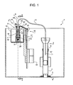
- Figure 1 diagrammatically and partially shows, with parts not in scale, a flushing tank 1 for bathroom appliances.
- the tank 1 comprises a flush valve 2 and a dosing device 3 for dosing a service liquid, for example (but not necessarily) a detergent and/or disinfection liquid or other type of water treatment liquid, in the water stream which is discharged from the flushing tank 1 by means of the flush valve 2.
- a service liquid for example (but not necessarily) a detergent and/or disinfection liquid or other type of water treatment liquid
- the flush valve 2 is of a known type and is shown only diagrammatically and partially in figure 1 ; in general terms, the flush valve 2 comprises a vertically slidable tubular body 4, which is provided below with a shutter 5 cooperating with a sealing seat 6 for closing a drain hole of the tank 1; the tubular body 4, which also constitutes an overflow tube 8, is raised by means of a known actuating mechanism (not shown).
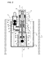
- the dosing device 3 comprises a reservoir 10 containing the service liquid, a pumping system 11 and a supply tube 12.
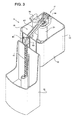
- the reservoir 10 comprises a cup-shaped body 13 open at the top, housed inside the tank 1 and positioned and shaped so as the water contained in the tank 1 does not enter inside the reservoir 10.
- the pumping system 11 comprises: a tubular dosing chamber 14, extending along a substantially vertical axis A between an upper axial end 15 and a lower axial end 16 and housed inside the reservoir 10 and integral with the reservoir 10; a piston 17 slidable in the chamber 14 along the axis A and operated by a float 18 by means of a lever system 19, and a lateral delivery conduit 20 communicating with the chamber 14.
- the chamber 14 is delimited by a lateral wall 21 and is joined below to a support piece 21A which projects from a bottom wall of cup-shaped body 13; the support piece 21A and the chamber 14 comprise a lower compartment 22 and an upper compartment 23, respectively, arranged along the axis A and separated by a transverse partition 24 provided with an opening 25 through which the piston 17 is arranged, with radial clearance.
- the lower compartment 22 of the chamber 14 has at least one inlet opening 26 arranged at the lower axial end 16 and communicating with the reservoir 10 to allow service liquid to enter from the reservoir 10 inside the chamber 14.
- the upper compartment 23 of the chamber 14 has a delivery opening 27, formed for example by means of the lateral wall 21 of the chamber 14 and set higher than the inlet opening 26; the delivery opening 27 connects the chamber 14 and precisely the upper compartment 23 with the delivery conduit 20.
- the chamber 14 is provided with a non-return valve 31, arranged at the lower axial end 16 of the chamber 14 in the lower compartment 22 above the inlet opening 26 and which allows the passage of fluids from the bottom upwards, but not vice versa; for example, the valve 31 comprises a sphere 32 which is vertically movable in the chamber 14 and cooperates with a sealing seat 33 formed inside the chamber 14.
- the piston 17 is provided with a radial sealing main gasket 34, which is arranged close to an upper head 35 of the piston 17, above the delivery opening 27, and is radially forced coupled and slidingly cooperates with an inner surface of the chamber 14 and precisely of the upper compartment 23; and with an auxiliary gasket 36, arranged at a lower end 37 of the piston 17 opposite the head 35 and axially cooperating, when the piston 17 is raised vertically, with a sealing seat 39 defined by a peripheral edge of the opening 25 to close the opening 25; when the piston 17 is lowered, on the other hand, it rests on an axial shoulder 38 formed in the lower compartment 22, above the non-return valve 31, and delimiting an opening which is not closed by gasket 36.
- a radial sealing main gasket 34 which is arranged close to an upper head 35 of the piston 17, above the delivery opening 27, and is radially forced coupled and slidingly cooperates with an inner surface of the chamber 14 and precisely of the upper compartment 23
- an auxiliary gasket 36 arranged at a lower end 37 of the piston
- the float 18 is arranged outside the reservoir 10 and is supported by the reservoir 10 by means of the lever system 19; the float 18 is slidable vertically along a guide 40 formed on a wall of the cup-shaped body 13 and projects downwards from the reservoir 10 so as to be movable, in use, by effect of level changes of the water contained in the tank 1.
- the lever system 19 comprises a substantially vertical stem 41 connected to the float 18, an arm 42 having opposite longitudinal ends which are hinged, respectively, to an upper head 43 of the stem 41 and to a support 44 which projects from the upper axial end 15 of the chamber 14, and a traction bar 45 hinged above to the arm 42 and connected below to the head 35 of the piston 17.
- the delivery conduit 20 comprises a portion 50 which projects laterally from the chamber 14 and a portion 51 which is substantially parallel to the chamber 14 and the axis A; the portion 50 communicates with the chamber 14 by means of the delivery opening 27; the portion 51 is provided with a non-return valve 52 which allows the passage of fluids from the bottom upwards, but not vice versa; for example, the valve 52 comprises a sphere or a pair of overlapping spheres 53 which are vertically movable in the portion 51 and cooperate with a sealing seat 54 formed inside the portion 51.
- the supply tube 12 for example constituted by a flexible tube, has an end 55 which is connected, for example by means of a connection 56, to the delivery conduit 20, and an end 57 arranged inside the overflow tube 8 (i.e. the tubular body 4).
- the float 18 of the pumping system 11 moves upwards to an upper position, and also moves piston 17 in the same direction (upwards) so favouring the filling of the dosing chamber 14 with the service liquid which is drawn from the reservoir 10 through the inlet opening 26; the movement of the piston 17 opens the sealing seat 38 and the service liquid specifically fills the lower compartment 22 and, through the opening 25, the upper compartment 23. During the upward movement of the piston 17, the piston 17 therefore draws service liquid from the reservoir 10 in the chamber 14.
- the piston 17 closes the auxiliary opening 25 with the gasket 36, ensuring the anti-siphoning.
- the service liquid mixes with the water of the tank 1 only at the moment of the flush without contaminating the inside of the tank 1.
Landscapes
- Health & Medical Sciences (AREA)
- Public Health (AREA)
- Engineering & Computer Science (AREA)
- Water Supply & Treatment (AREA)
- Life Sciences & Earth Sciences (AREA)
- Hydrology & Water Resources (AREA)
- Epidemiology (AREA)
- Mechanical Engineering (AREA)
- Devices For Dispensing Beverages (AREA)
- Float Valves (AREA)
- Photographic Developing Apparatuses (AREA)
- Cleaning By Liquid Or Steam (AREA)
- Photographic Processing Devices Using Wet Methods (AREA)
Applications Claiming Priority (1)
| Application Number | Priority Date | Filing Date | Title |
|---|---|---|---|
| IT001038A ITTO20111038A1 (it) | 2011-11-10 | 2011-11-10 | Dispositivo dosatore di un liquido di servizio per una cassetta di risciacquo, e cassetta di risciacquo provvista di tale dispositivo dosatore |
Publications (1)
| Publication Number | Publication Date |
|---|---|
| EP2592193A1 true EP2592193A1 (en) | 2013-05-15 |
Family
ID=45044658
Family Applications (1)
| Application Number | Title | Priority Date | Filing Date |
|---|---|---|---|
| EP12398007.0A Withdrawn EP2592193A1 (en) | 2011-11-10 | 2012-11-09 | Dosing device of a service liquid for a flushing tank, and flushing tank provided with said device |
Country Status (4)
| Country | Link |
|---|---|
| EP (1) | EP2592193A1 (it) |
| AU (1) | AU2012247074A1 (it) |
| IT (1) | ITTO20111038A1 (it) |
| RU (1) | RU2610122C2 (it) |
Cited By (2)
| Publication number | Priority date | Publication date | Assignee | Title |
|---|---|---|---|---|
| CN111335426A (zh) * | 2018-12-18 | 2020-06-26 | 德尔塔阀门公司 | 用于安装在马桶水箱中的冲洗阀以及用于清洁马桶的方法 |
| CN118911253A (zh) * | 2024-08-21 | 2024-11-08 | 泉州科牧智能厨卫有限公司 | 一种加液装置及其智能座便器 |
Citations (4)
| Publication number | Priority date | Publication date | Assignee | Title |
|---|---|---|---|---|
| US1087060A (en) * | 1910-12-03 | 1914-02-10 | James Gilson | Disinfectant device. |
| US2243454A (en) * | 1939-12-30 | 1941-05-27 | Lee C Collinge | Dispenser for disinfectants |
| GB1364063A (en) * | 1972-08-03 | 1974-08-21 | Uni Hygea Ltd | Fluid dispensing devices |
| US3999226A (en) * | 1975-06-23 | 1976-12-28 | Tobin Wolf | Toilet sanitizer with disposable container |
Family Cites Families (5)
| Publication number | Priority date | Publication date | Assignee | Title |
|---|---|---|---|---|
| US4312082A (en) * | 1980-06-30 | 1982-01-26 | Shell Oil Company | Dispensing apparatus for toilets |
| GB9617124D0 (en) * | 1996-08-15 | 1996-09-25 | Ghobrial Abraam R | Improvement in the lavatory |
| WO2002061212A1 (en) * | 2001-01-29 | 2002-08-08 | Jan Nowak | A flush, particularly for sanitary facilities |
| FR2887904B1 (fr) * | 2005-07-01 | 2007-09-28 | Gilles Allard | Dispositif distributeur d'un produit nettoyant |
| RU2009117985A (ru) * | 2009-05-12 | 2010-11-20 | Владимир Александрович Парамошко (RU) | Устройство для дезинфекции и ароматизации смывной воды |
-
2011
- 2011-11-10 IT IT001038A patent/ITTO20111038A1/it unknown
-
2012
- 2012-11-09 AU AU2012247074A patent/AU2012247074A1/en not_active Abandoned
- 2012-11-09 RU RU2012147855A patent/RU2610122C2/ru not_active IP Right Cessation
- 2012-11-09 EP EP12398007.0A patent/EP2592193A1/en not_active Withdrawn
Patent Citations (4)
| Publication number | Priority date | Publication date | Assignee | Title |
|---|---|---|---|---|
| US1087060A (en) * | 1910-12-03 | 1914-02-10 | James Gilson | Disinfectant device. |
| US2243454A (en) * | 1939-12-30 | 1941-05-27 | Lee C Collinge | Dispenser for disinfectants |
| GB1364063A (en) * | 1972-08-03 | 1974-08-21 | Uni Hygea Ltd | Fluid dispensing devices |
| US3999226A (en) * | 1975-06-23 | 1976-12-28 | Tobin Wolf | Toilet sanitizer with disposable container |
Cited By (2)
| Publication number | Priority date | Publication date | Assignee | Title |
|---|---|---|---|---|
| CN111335426A (zh) * | 2018-12-18 | 2020-06-26 | 德尔塔阀门公司 | 用于安装在马桶水箱中的冲洗阀以及用于清洁马桶的方法 |
| CN118911253A (zh) * | 2024-08-21 | 2024-11-08 | 泉州科牧智能厨卫有限公司 | 一种加液装置及其智能座便器 |
Also Published As
| Publication number | Publication date |
|---|---|
| AU2012247074A1 (en) | 2013-05-30 |
| ITTO20111038A1 (it) | 2013-05-11 |
| RU2610122C2 (ru) | 2017-02-08 |
| RU2012147855A (ru) | 2014-05-20 |
Similar Documents
| Publication | Publication Date | Title |
|---|---|---|
| US4064572A (en) | Level actuated apparatus for delivering chemicals | |
| US20100299824A1 (en) | Jet Powered Toilet Flushing System | |
| US11021863B2 (en) | Pre-primed siphonic toilet | |
| CN107532747A (zh) | 虹吸式致动阀 | |
| US9869080B2 (en) | Cleaning liquid dispenser | |
| US9611632B2 (en) | Toilet controls | |
| EA039580B1 (ru) | Устройство для туалетов | |
| EP2696003A1 (en) | Flush tank service liquid dispenser device | |
| EP2592193A1 (en) | Dosing device of a service liquid for a flushing tank, and flushing tank provided with said device | |
| JP6187759B2 (ja) | 水洗大便器装置 | |
| CN105605292B (zh) | 液体中置式限量排放控制器 | |
| JP4958070B2 (ja) | 水洗便器 | |
| JP6361856B2 (ja) | 水洗大便器装置 | |
| JP2018100575A (ja) | 水洗大便器 | |
| EP3009573B1 (en) | Dosing device of a service liquid for a flushing tank, and flushing tank provided with such a dosing device | |
| EP2650450B1 (en) | Dispenser device of a service liquid for a flushing tank | |
| AU2017201777B2 (en) | A WC Suite | |
| RU2283928C1 (ru) | Сливная арматура | |
| JP2019203256A (ja) | 便器システム | |
| US20220316196A1 (en) | System and method for self-cleaning toilet rim | |
| RU107800U1 (ru) | Клапан с двойным сливом | |
| US881145A (en) | Flushing-tank. | |
| EP2803773A1 (en) | Toilet flushing system | |
| US638441A (en) | Flushing apparatus for bowls, tanks, &c. | |
| US292901A (en) | demajrest |
Legal Events
| Date | Code | Title | Description |
|---|---|---|---|
| PUAI | Public reference made under article 153(3) epc to a published international application that has entered the european phase |
Free format text: ORIGINAL CODE: 0009012 |
|
| AK | Designated contracting states |
Kind code of ref document: A1 Designated state(s): AL AT BE BG CH CY CZ DE DK EE ES FI FR GB GR HR HU IE IS IT LI LT LU LV MC MK MT NL NO PL PT RO RS SE SI SK SM TR |
|
| AX | Request for extension of the european patent |
Extension state: BA ME |
|
| 17P | Request for examination filed |
Effective date: 20131115 |
|
| RBV | Designated contracting states (corrected) |
Designated state(s): AL AT BE BG CH CY CZ DE DK EE ES FI FR GB GR HR HU IE IS IT LI LT LU LV MC MK MT NL NO PL PT RO RS SE SI SK SM TR |
|
| STAA | Information on the status of an ep patent application or granted ep patent |
Free format text: STATUS: THE APPLICATION IS DEEMED TO BE WITHDRAWN |
|
| 18D | Application deemed to be withdrawn |
Effective date: 20160601 |