EP2592199A1 - Tour pour une éolienne - Google Patents
Tour pour une éolienne Download PDFInfo
- Publication number
- EP2592199A1 EP2592199A1 EP12191435.2A EP12191435A EP2592199A1 EP 2592199 A1 EP2592199 A1 EP 2592199A1 EP 12191435 A EP12191435 A EP 12191435A EP 2592199 A1 EP2592199 A1 EP 2592199A1
- Authority
- EP
- European Patent Office
- Prior art keywords
- tower
- transition body
- lattice
- section
- tower according
- Prior art date
- Legal status (The legal status is an assumption and is not a legal conclusion. Google has not performed a legal analysis and makes no representation as to the accuracy of the status listed.)
- Granted
Links
Images


Classifications
-
- E—FIXED CONSTRUCTIONS
- E04—BUILDING
- E04H—BUILDINGS OR LIKE STRUCTURES FOR PARTICULAR PURPOSES; SWIMMING OR SPLASH BATHS OR POOLS; MASTS; FENCING; TENTS OR CANOPIES, IN GENERAL
- E04H12/00—Towers; Masts or poles; Chimney stacks; Water-towers; Methods of erecting such structures
- E04H12/02—Structures made of specified materials
- E04H12/08—Structures made of specified materials of metal
- E04H12/10—Truss-like structures
-
- E—FIXED CONSTRUCTIONS
- E04—BUILDING
- E04H—BUILDINGS OR LIKE STRUCTURES FOR PARTICULAR PURPOSES; SWIMMING OR SPLASH BATHS OR POOLS; MASTS; FENCING; TENTS OR CANOPIES, IN GENERAL
- E04H12/00—Towers; Masts or poles; Chimney stacks; Water-towers; Methods of erecting such structures
- E04H12/02—Structures made of specified materials
- E04H12/08—Structures made of specified materials of metal
-
- F—MECHANICAL ENGINEERING; LIGHTING; HEATING; WEAPONS; BLASTING
- F03—MACHINES OR ENGINES FOR LIQUIDS; WIND, SPRING, OR WEIGHT MOTORS; PRODUCING MECHANICAL POWER OR A REACTIVE PROPULSIVE THRUST, NOT OTHERWISE PROVIDED FOR
- F03D—WIND MOTORS
- F03D13/00—Assembly, mounting or commissioning of wind motors; Arrangements specially adapted for transporting wind motor components
- F03D13/20—Arrangements for mounting or supporting wind motors; Masts or towers for wind motors
-
- E—FIXED CONSTRUCTIONS
- E04—BUILDING
- E04H—BUILDINGS OR LIKE STRUCTURES FOR PARTICULAR PURPOSES; SWIMMING OR SPLASH BATHS OR POOLS; MASTS; FENCING; TENTS OR CANOPIES, IN GENERAL
- E04H12/00—Towers; Masts or poles; Chimney stacks; Water-towers; Methods of erecting such structures
- E04H2012/006—Structures with truss-like sections combined with tubular-like sections
-
- F—MECHANICAL ENGINEERING; LIGHTING; HEATING; WEAPONS; BLASTING
- F05—INDEXING SCHEMES RELATING TO ENGINES OR PUMPS IN VARIOUS SUBCLASSES OF CLASSES F01-F04
- F05B—INDEXING SCHEME RELATING TO WIND, SPRING, WEIGHT, INERTIA OR LIKE MOTORS, TO MACHINES OR ENGINES FOR LIQUIDS COVERED BY SUBCLASSES F03B, F03D AND F03G
- F05B2240/00—Components
- F05B2240/90—Mounting on supporting structures or systems
- F05B2240/91—Mounting on supporting structures or systems on a stationary structure
- F05B2240/912—Mounting on supporting structures or systems on a stationary structure on a tower
- F05B2240/9121—Mounting on supporting structures or systems on a stationary structure on a tower on a lattice tower
-
- F—MECHANICAL ENGINEERING; LIGHTING; HEATING; WEAPONS; BLASTING
- F05—INDEXING SCHEMES RELATING TO ENGINES OR PUMPS IN VARIOUS SUBCLASSES OF CLASSES F01-F04
- F05B—INDEXING SCHEME RELATING TO WIND, SPRING, WEIGHT, INERTIA OR LIKE MOTORS, TO MACHINES OR ENGINES FOR LIQUIDS COVERED BY SUBCLASSES F03B, F03D AND F03G
- F05B2240/00—Components
- F05B2240/90—Mounting on supporting structures or systems
- F05B2240/91—Mounting on supporting structures or systems on a stationary structure
- F05B2240/913—Mounting on supporting structures or systems on a stationary structure on a mast
-
- Y—GENERAL TAGGING OF NEW TECHNOLOGICAL DEVELOPMENTS; GENERAL TAGGING OF CROSS-SECTIONAL TECHNOLOGIES SPANNING OVER SEVERAL SECTIONS OF THE IPC; TECHNICAL SUBJECTS COVERED BY FORMER USPC CROSS-REFERENCE ART COLLECTIONS [XRACs] AND DIGESTS
- Y02—TECHNOLOGIES OR APPLICATIONS FOR MITIGATION OR ADAPTATION AGAINST CLIMATE CHANGE
- Y02E—REDUCTION OF GREENHOUSE GAS [GHG] EMISSIONS, RELATED TO ENERGY GENERATION, TRANSMISSION OR DISTRIBUTION
- Y02E10/00—Energy generation through renewable energy sources
- Y02E10/70—Wind energy
- Y02E10/72—Wind turbines with rotation axis in wind direction
-
- Y—GENERAL TAGGING OF NEW TECHNOLOGICAL DEVELOPMENTS; GENERAL TAGGING OF CROSS-SECTIONAL TECHNOLOGIES SPANNING OVER SEVERAL SECTIONS OF THE IPC; TECHNICAL SUBJECTS COVERED BY FORMER USPC CROSS-REFERENCE ART COLLECTIONS [XRACs] AND DIGESTS
- Y02—TECHNOLOGIES OR APPLICATIONS FOR MITIGATION OR ADAPTATION AGAINST CLIMATE CHANGE
- Y02E—REDUCTION OF GREENHOUSE GAS [GHG] EMISSIONS, RELATED TO ENERGY GENERATION, TRANSMISSION OR DISTRIBUTION
- Y02E10/00—Energy generation through renewable energy sources
- Y02E10/70—Wind energy
- Y02E10/728—Onshore wind turbines
Definitions
- This invention relates to a tower for a wind energy device, including a lattice tower part which has a polygonal cross section at least at a top, and a tubular tower part extending thereabove which has a substantially circular cross section at the bottom.
- Such a tower is known, for example, from WO2008/064861 .
- a frustoconical envelope is provided to couple a lattice tower to a tubular tower part.
- a disadvantage of that configuration is that it is relatively weak and requires relatively much material.
- the conical bending of plate material is rather laborious and relatively difficult since bending is to be done about two different axes.
- the present invention contemplates an improved tower for a wind energy device.
- a tower is characterized by the features of claim 1.
- the lattice tower part and the tubular tower part are coupled to each other by means of a transition body, wherein the lattice tower part extends partly along the transition body, wherein the transition body includes a lowermost part having a polygonal cross section adapted to the lattice tower part, as well as an uppermost part having a circular cross section adapted to the circular cross section of the tubular tower part.
- Fig. 1 shows a part of a tower known from the prior art ( W02008/064861 ), which tower includes a tubular upper part 2 having a substantially round (circular) cross section at least at the bottom, as well as a lattice tower part 101 which has a polygonal cross section at least at a top, and a transition body 103 extending between the tower parts 101, 2.
- Corners of the lattice tower part 101 are defined by respective substantially vertical corner posts/legs.
- an uppermost part of the lattice tower part 101 extends along the transition body 103, in a vertical direction, i.e., the uppermost part of the lattice tower part 101 extends into a transition region defined by the transition body 103.
- the transition body 103 is implemented as a frustoconical envelope.
- a lattice tower part 101 as mentioned and the tubular upper part 2 may be designed in different manners, which will be clear to those skilled in the art.
- the lattice tower part 101 can have, for example, a triangular cross section, with three posts, or a quadrangular cross section, with four posts, or an otherwise polygonal cross section.
- the lattice tower part 101 comprises a number of corner posts or main legs B, which extend somewhat obliquely upwards (and converge mutually), preferably in a mutually symmetrical arrangement (in particular with rotational symmetry relative to a central vertical axis of symmetry).
- the main legs B are coupled to each other by multiple cross connections so as to provide a relatively stiff and strong construction.
- the main legs B are tubular (in particular having a constant circular diameter).
- the tubular upper part 2 can comprise a substantially closed envelope, preferably having a circular cross section throughout its length, which may or may not have a substantially constant diameter.
- the upper part 2 is provided at the top with a generator (normally with blades) known per se, not represented, which is configured to generate electricity from wind power.
- the upper part 2 may for instance be coupled to the transition body 103 by means of a suitable flange coupling 105. After assembly, the tubular upper part 2 extends in particular centrally above the lattice part 101 (i.e., with longitudinal centerlines mutually aligned).
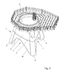
- Fig. 2 shows a part of an exemplary embodiment according to the present invention.
- the exemplary embodiment comprises a transition body 3 to couple a lattice tower part 1 (of which only a top part, viz., uppermost sections of respective main legs B, is visible) to a tubular upper part 2 (not shown in Fig. 2 ), for example, via a circular flange 5.
- the exemplary embodiment differs from the known configuration shown in Fig. 1 in that the transition body 103 is not implemented as a frustoconical envelope.
- the exemplary embodiment includes a transition body 3 which has a lowermost part with a polygonal cross section adapted specifically to the lattice tower part. Further, the transition body 3 includes an uppermost part having a circular cross section adapted to the circular cross section of the tubular tower part.
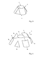
- a basic configuration of the transition body 3 is represented in Figs. 3-4 .
- the transition body 3 in this example includes a multiangular bottom edge E (having as many angles as the number of angles of the lattice tower, viz., three in this example), with a multiangular contour between the bottom edge and a circular top edge C.
- the transition body 3 is provided with substantially rounded external corners, and straight, flat parts extending therebetween.
- the transition body 3 is substantially, and preferably completely, manufactured of plate material, for example, of steel.
- the transition body 3 is provided with a number of mutually coupled, substantially straight (i.e., non-curved) plate parts 3a, which extend between the corners of the body.
- the straight plate parts 3a after tower assembly, can extend, for example, parallel to longitudinal sides of the subjacent lattice tower 1 (these longitudinal sides being defined in particular by planes extending between each pair of adjacent corner legs B).
- the straight plate parts are substantially triangle-shaped plate parts 3a.
- Each of these plate parts 3a is provided with a top point/corner which is at or near the circular top edge C.
- the remaining two points/corners of each of the triangular plate parts 3a are at or near the bottom edge E of the transition body 3 shown.
- the straight plate parts 3a can be coupled to each other in different manners, for example, through direct welded joints and/or via angle sections or the like.
- the transition body 3 includes a number of bent plate parts 3b which each have a substantially constant radius of curvature, and in particular comprise circular cylinder sections.
- bent plate parts 3b may be formed, for example, by roll bending a flat plate or by cutting-through a circular cylinder tube or casing, or in a different manner.
- the present bent plate parts 3b viewed in a transversal cross section, have a slightly elliptical curvature. This can be achieved, for example, by roll bending a flat plate or by cutting-through a circular cylinder tube or casing slightly obliquely, which will be clear to those skilled in the art.
- the curved plate parts 3b may each be formed such that these parts 3b, at least at one end, are provided with a circular section-shaped end edge D.
- the (circular) top edge C of the transition body 3 is formed by the circular section-shaped end edges D of the plate parts 3b mentioned.
- the end edges D of the bent plate parts 3b may be fixed to a strengthening element, for example, a ring-shaped or plate-shaped element 3c, and may be attached, for example, directly or indirectly, to a flange 5 as mentioned (to receive/carry an upper tower part 2).
- bent plate parts 3b described here can be manufactured relatively simply, for example, in a cutting process, a rolling process and/or both.
- a rolling process can be carried out particularly simply.
- these curved plate parts form the corners of the body 3, and couple the straight plate parts 3a.
- the various plate parts 3a, 3b can be fixed to each other in different manners, for example, by means of welded joints.
- the transition body 3 in a further elaboration may be provided, along a bottom edge, with recesses situated between lowermost corner parts 3d, for example, substantially V-shaped or substantially U-shaped recesses U.
- the lowermost corner parts 3d can comprise, for example, lowermost sections of the bent (plate) parts 3b.
- each flat side of the transition body 3 may be formed, for example, by one or several respective flat plate parts 3a.
- each bent corner part 3b of the transition body 3 may be formed, for example, by one or several respective bent plate parts 3b. These several plate parts for forming a bent part 3b or flat part 3a may be fixed to each other, for example, through suitable welded joints, which will be clear to those skilled in the art.
- the lattice tower 1 may by an upper part thereof, viz., uppermost sections (end parts) of the legs B, be slot-connected ("slotted in") with the transition body, and preferably be welded together.
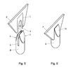
- Figs. 5 and 6 show a preferred embodiment of such a coupling, i.e., between a plate part P which represents a corner part 3d of the transition body 3, and a main leg B of the lattice tower part 1.
- a straight plate part P is shown as corner part 3d. It will be clear that the plate part can also be a curved corner part 3b, 3d (as in Fig. 2 ).
- the corner parts P (3b, 3d) of the transition body 3 can each be provided, in a bottom edge thereof, with a recess 7, for example, a substantially U-shaped notch, which extends within a welding area indicated with broken lines L.
- a recess 7 for example, a substantially U-shaped notch, which extends within a welding area indicated with broken lines L.
- the broken lines L are, in particular, welding seam locations, where edges of the leg B to be fixed, touch, upon assembly, the corner part P (3b, 3d) (and along those welding locations are fixed to the corner part 3d through welded joints).
- Tubular end parts of the legs B can each be provided with slots 8 to engage the transition body 3, and in particular to slide over a corner part P (3b, 3d) over a defined distance.
- the tube wall of each leg B may, for example, be advantageously provided with two parallel straight slots 8 extending opposite each other, for receiving a corner part 3b, 3d (curved about one single axis).
- tubular parts of the legs B may be designed, for example, to be slid substantially throughout the height of the transition body 3 onto the corners of that body, via respective slots 8.
- the legs may be slid, for example, over just a relatively short distance onto the corners 3d of the transition body.
- Figs. 2 and 6 show the slot fixation after assembly, with the legs B each welded via slot edges to the plate material (P) of the transition body, along respective welding lines L.
- tubular upper parts of the legs B are furthermore provided with tapering tube parts F extending along the respective slots 8, to reduce stress concentrations.
- cover plates G are provided (in this case elliptically shaped plates G) to close off the tubular upper parts along the tapering edges.
- Building the tower can comprise, for example, the following steps, in a random order:
- the transition body 3 can be arranged at different moments, for example, prior to and/or during placement of the lattice tower part, which will be clear to those skilled in the art. Owing to the above-described configuration, a relatively rapid and accurate assembly of the tower can be achieved. In addition, the tower can be built from relatively little material, especially with a transition body 3 constructed from relatively little (plate) material. Moreover, the shape of the transition body 3 leads to a very stable and strong construction.
- Fig. 7 shows an alternative, likewise advantageous, elaboration of the invention, which is different from the example shown in Figs. 2-4 in that the transition body 3' is provided with a circular cylinder-shaped upper part 13 which has a constant diameter.
- the circular cylinder-shaped upper part 13 may be provided with optional corner parts 13a (e.g., tube sections 13a) to provide a polygonal cross section adapted to the lattice tower part 1 (i.e., the legs B).
- the uppermost part of the circular cylinder-shaped part 13 has a diameter associated with the tubular tower part.
- the transition body 3' is provided with corner leg parts 3d' extending under the circular cylinder-shaped upper part 13, which receive the lattice tower legs B (and, for example, are fixed thereto through the above-described slot-weld connections).
- the corner leg parts 3d' are preferably curved plate parts, and preferably have each a substantially constant radius of curvature (to this end, the corner leg parts 3d' may comprise, for example, circular cylinder sections).
- the curved corner leg parts 3d' can each be formed such that these parts 3d' are provided at least at one end with a circular section-shaped end edge D, which adjoins a circular bottom edge of the cylinder part 13.
Landscapes
- Engineering & Computer Science (AREA)
- Architecture (AREA)
- Chemical & Material Sciences (AREA)
- Life Sciences & Earth Sciences (AREA)
- Civil Engineering (AREA)
- Wood Science & Technology (AREA)
- Materials Engineering (AREA)
- Structural Engineering (AREA)
- Sustainable Development (AREA)
- Sustainable Energy (AREA)
- Combustion & Propulsion (AREA)
- Mechanical Engineering (AREA)
- General Engineering & Computer Science (AREA)
- Wind Motors (AREA)
Applications Claiming Priority (1)
| Application Number | Priority Date | Filing Date | Title |
|---|---|---|---|
| NL2007759A NL2007759C2 (nl) | 2011-11-09 | 2011-11-09 | Toren voor een windenergieinrichting. |
Publications (2)
| Publication Number | Publication Date |
|---|---|
| EP2592199A1 true EP2592199A1 (fr) | 2013-05-15 |
| EP2592199B1 EP2592199B1 (fr) | 2017-04-26 |
Family
ID=47080381
Family Applications (1)
| Application Number | Title | Priority Date | Filing Date |
|---|---|---|---|
| EP12191435.2A Active EP2592199B1 (fr) | 2011-11-09 | 2012-11-06 | Tour pour une éolienne |
Country Status (2)
| Country | Link |
|---|---|
| EP (1) | EP2592199B1 (fr) |
| NL (1) | NL2007759C2 (fr) |
Cited By (5)
| Publication number | Priority date | Publication date | Assignee | Title |
|---|---|---|---|---|
| DE102013110495A1 (de) * | 2013-09-23 | 2015-03-26 | Thyssenkrupp Steel Europe Ag | Übergangskörper zwischen Turmabschnitten einer Windkraftanlage und Turm einer Windkraftanlage umfassend einen Übergangskörper |
| WO2015150593A1 (fr) * | 2014-03-04 | 2015-10-08 | Nabrawind Sl | Liaison entre mât en treillis et nacelle |
| EP3450748A4 (fr) * | 2017-03-03 | 2019-07-24 | Qingdao Hua-Strong Energy Technology Co., Ltd. | Structure de liaison pour armature de tube d'acier et corps de tour d'une tour de génération d'énergie éolienne en treillis, tour éolienne polygonale précontrainte munie d'une poutre de caisson circulaire pour ventilateur direct au sommet d'une tour, tour de génération d'énergie éolienne et tour éolienne ayant une structure anti-fatigue précontrainte |
| US20190249647A1 (en) * | 2016-09-09 | 2019-08-15 | Siemens Gamesa Renewable Energy A/S | Transition piece for a wind turbine |
| CN114215699A (zh) * | 2021-12-16 | 2022-03-22 | 珠海巨涛海洋石油服务有限公司 | 一种海上风电导管架过渡段及其组装工艺 |
Citations (8)
| Publication number | Priority date | Publication date | Assignee | Title |
|---|---|---|---|---|
| DE102005012817A1 (de) * | 2005-03-17 | 2006-09-21 | Seeba Technik Gmbh | Profilgestaltung |
| EP1729007A2 (fr) * | 2005-06-03 | 2006-12-06 | Gamesa Eolica, S.A.U. | Tour pour une éolienne |
| DE102005033600B3 (de) | 2005-07-14 | 2006-12-14 | Oehme, Hermann R. | Turm für eine Windenergieanlage |
| DE102005047961A1 (de) * | 2005-10-06 | 2007-04-12 | Seeba Technik Gmbh | Hybridturm |
| WO2008064861A2 (fr) | 2006-11-27 | 2008-06-05 | Repower Systems Ag | Tour d'une éolienne |
| EP2067915A2 (fr) * | 2007-12-04 | 2009-06-10 | WeserWind GmbH | Structure de grille d'une construction offshore, en particulier d'une éolienne offshore |
| GB2476051A (en) * | 2009-12-08 | 2011-06-15 | Atkins Ltd | Mast and truss structure suitable for wind turbines |
| US20110138721A1 (en) * | 2010-12-07 | 2011-06-16 | Bharat Sampathkumaran Bagepalli | Wind turbine tower assembly and method for assembling the same |
-
2011
- 2011-11-09 NL NL2007759A patent/NL2007759C2/nl not_active IP Right Cessation
-
2012
- 2012-11-06 EP EP12191435.2A patent/EP2592199B1/fr active Active
Patent Citations (8)
| Publication number | Priority date | Publication date | Assignee | Title |
|---|---|---|---|---|
| DE102005012817A1 (de) * | 2005-03-17 | 2006-09-21 | Seeba Technik Gmbh | Profilgestaltung |
| EP1729007A2 (fr) * | 2005-06-03 | 2006-12-06 | Gamesa Eolica, S.A.U. | Tour pour une éolienne |
| DE102005033600B3 (de) | 2005-07-14 | 2006-12-14 | Oehme, Hermann R. | Turm für eine Windenergieanlage |
| DE102005047961A1 (de) * | 2005-10-06 | 2007-04-12 | Seeba Technik Gmbh | Hybridturm |
| WO2008064861A2 (fr) | 2006-11-27 | 2008-06-05 | Repower Systems Ag | Tour d'une éolienne |
| EP2067915A2 (fr) * | 2007-12-04 | 2009-06-10 | WeserWind GmbH | Structure de grille d'une construction offshore, en particulier d'une éolienne offshore |
| GB2476051A (en) * | 2009-12-08 | 2011-06-15 | Atkins Ltd | Mast and truss structure suitable for wind turbines |
| US20110138721A1 (en) * | 2010-12-07 | 2011-06-16 | Bharat Sampathkumaran Bagepalli | Wind turbine tower assembly and method for assembling the same |
Cited By (10)
| Publication number | Priority date | Publication date | Assignee | Title |
|---|---|---|---|---|
| DE102013110495A1 (de) * | 2013-09-23 | 2015-03-26 | Thyssenkrupp Steel Europe Ag | Übergangskörper zwischen Turmabschnitten einer Windkraftanlage und Turm einer Windkraftanlage umfassend einen Übergangskörper |
| US10001111B2 (en) | 2013-09-23 | 2018-06-19 | Thyssenkrupp Steel Europe Ag | Transition body between tower sections of a wind turbine and wind turbine tower comprising same |
| WO2015150593A1 (fr) * | 2014-03-04 | 2015-10-08 | Nabrawind Sl | Liaison entre mât en treillis et nacelle |
| CN106536922A (zh) * | 2014-03-04 | 2017-03-22 | 纳巴风力公司 | 格塔和吊舱之间的连接 |
| US20190249647A1 (en) * | 2016-09-09 | 2019-08-15 | Siemens Gamesa Renewable Energy A/S | Transition piece for a wind turbine |
| US10767632B2 (en) * | 2016-09-09 | 2020-09-08 | Siemens Gamesa Renewable Energy A/S | Transition piece for a wind turbine |
| EP3450748A4 (fr) * | 2017-03-03 | 2019-07-24 | Qingdao Hua-Strong Energy Technology Co., Ltd. | Structure de liaison pour armature de tube d'acier et corps de tour d'une tour de génération d'énergie éolienne en treillis, tour éolienne polygonale précontrainte munie d'une poutre de caisson circulaire pour ventilateur direct au sommet d'une tour, tour de génération d'énergie éolienne et tour éolienne ayant une structure anti-fatigue précontrainte |
| US10823150B2 (en) | 2017-03-03 | 2020-11-03 | Qindao Hua-Strong Energy Technology Co., Ltd. | Connecting structure for steel tube truss and tower barrel of lattice wind power generation tower, prestressed polygon wind tower provided with circular box girder for direct fan on top of tower, wind power generation tower, and wind tower having prestressed anti-fatigue structure |
| CN114215699A (zh) * | 2021-12-16 | 2022-03-22 | 珠海巨涛海洋石油服务有限公司 | 一种海上风电导管架过渡段及其组装工艺 |
| CN114215699B (zh) * | 2021-12-16 | 2023-12-01 | 珠海巨涛海洋石油服务有限公司 | 一种海上风电导管架过渡段及其组装工艺 |
Also Published As
| Publication number | Publication date |
|---|---|
| NL2007759C2 (nl) | 2013-05-14 |
| EP2592199B1 (fr) | 2017-04-26 |
Similar Documents
| Publication | Publication Date | Title |
|---|---|---|
| EP2592199B1 (fr) | Tour pour une éolienne | |
| US9765547B2 (en) | Node structures for lattice frames | |
| EP2751424B1 (fr) | Structure de transition pour tour d'éolienne | |
| DK2877642T3 (en) | Node structures for grid racks | |
| ES2730968T3 (es) | Sección de torre de aerogenerador, torre de aerogenerador y procedimiento de ensamblaje | |
| JP2016502668A5 (fr) | ||
| EP2662495A1 (fr) | Fondation d'éolienne | |
| WO2011029994A1 (fr) | Élément de liaison et structure d'armature radiale | |
| EP2857614A1 (fr) | Tour de béton formée de pièces préfabriquées | |
| CN102817327A (zh) | 用于钢管拱桥操作平台的爬梯装置及其搭设方法 | |
| CN205077917U (zh) | 一种轻巧载车板 | |
| CN201649770U (zh) | 三管通讯塔 | |
| JP6664648B1 (ja) | パイプ一体型ラセン杭、パイプ一体型ラセン杭の製造方法および構造物 | |
| TWM404858U (en) | Composite construction of steel pipe and sheet pile | |
| FI122863B (fi) | Ristikkorakenteinen masto | |
| CN104234210B (zh) | 一种预制梁柱节点的钢筋连接装置及其施工方法 | |
| CN209509620U (zh) | 用于塔筒段的弧形塔片和塔筒段 | |
| CN206438753U (zh) | 脚手架钢管简易校直架 | |
| ES2629607B2 (es) | Dispositivo conector para estructuras colaborantes de madera y hormigón y estructura mixta que incorpora una pluralidad de dispositivos conectores | |
| US20250392250A1 (en) | Terrain following support systems and installation methods for solar energy modules | |
| CN204967128U (zh) | 一种塔桥式公路跨越架 | |
| CN218346565U (zh) | 一种一体化钢筋上下保护层专用马镫 | |
| KR20110106085A (ko) | 탱크 제조 방법 | |
| CN201385673Y (zh) | 登高脚踏 | |
| ES2587677T3 (es) | Procedimiento para la fabricación de estructuras tubulares, así como bastidor de montaje |
Legal Events
| Date | Code | Title | Description |
|---|---|---|---|
| PUAI | Public reference made under article 153(3) epc to a published international application that has entered the european phase |
Free format text: ORIGINAL CODE: 0009012 |
|
| AK | Designated contracting states |
Kind code of ref document: A1 Designated state(s): AL AT BE BG CH CY CZ DE DK EE ES FI FR GB GR HR HU IE IS IT LI LT LU LV MC MK MT NL NO PL PT RO RS SE SI SK SM TR |
|
| AX | Request for extension of the european patent |
Extension state: BA ME |
|
| 17P | Request for examination filed |
Effective date: 20131114 |
|
| RBV | Designated contracting states (corrected) |
Designated state(s): AL AT BE BG CH CY CZ DE DK EE ES FI FR GB GR HR HU IE IS IT LI LT LU LV MC MK MT NL NO PL PT RO RS SE SI SK SM TR |
|
| RAP1 | Party data changed (applicant data changed or rights of an application transferred) |
Owner name: KCI THE ENGINEERS B.V. |
|
| 17Q | First examination report despatched |
Effective date: 20150623 |
|
| GRAP | Despatch of communication of intention to grant a patent |
Free format text: ORIGINAL CODE: EPIDOSNIGR1 |
|
| INTG | Intention to grant announced |
Effective date: 20160506 |
|
| RIN1 | Information on inventor provided before grant (corrected) |
Inventor name: VAN GELDER, KLAAS BOUDEWIJN Inventor name: KORNDORFFER, DIETER |
|
| RAP1 | Party data changed (applicant data changed or rights of an application transferred) |
Owner name: KCI THE ENGINEERS B.V. |
|
| GRAJ | Information related to disapproval of communication of intention to grant by the applicant or resumption of examination proceedings by the epo deleted |
Free format text: ORIGINAL CODE: EPIDOSDIGR1 |
|
| INTC | Intention to grant announced (deleted) | ||
| GRAP | Despatch of communication of intention to grant a patent |
Free format text: ORIGINAL CODE: EPIDOSNIGR1 |
|
| INTG | Intention to grant announced |
Effective date: 20161014 |
|
| GRAS | Grant fee paid |
Free format text: ORIGINAL CODE: EPIDOSNIGR3 |
|
| GRAA | (expected) grant |
Free format text: ORIGINAL CODE: 0009210 |
|
| AK | Designated contracting states |
Kind code of ref document: B1 Designated state(s): AL AT BE BG CH CY CZ DE DK EE ES FI FR GB GR HR HU IE IS IT LI LT LU LV MC MK MT NL NO PL PT RO RS SE SI SK SM TR |
|
| REG | Reference to a national code |
Ref country code: GB Ref legal event code: FG4D |
|
| REG | Reference to a national code |
Ref country code: CH Ref legal event code: EP |
|
| REG | Reference to a national code |
Ref country code: AT Ref legal event code: REF Ref document number: 888021 Country of ref document: AT Kind code of ref document: T Effective date: 20170515 |
|
| REG | Reference to a national code |
Ref country code: IE Ref legal event code: FG4D |
|
| REG | Reference to a national code |
Ref country code: DE Ref legal event code: R096 Ref document number: 602012031565 Country of ref document: DE |
|
| REG | Reference to a national code |
Ref country code: NL Ref legal event code: FP |
|
| REG | Reference to a national code |
Ref country code: LT Ref legal event code: MG4D |
|
| REG | Reference to a national code |
Ref country code: AT Ref legal event code: MK05 Ref document number: 888021 Country of ref document: AT Kind code of ref document: T Effective date: 20170426 |
|
| PG25 | Lapsed in a contracting state [announced via postgrant information from national office to epo] |
Ref country code: GR Free format text: LAPSE BECAUSE OF FAILURE TO SUBMIT A TRANSLATION OF THE DESCRIPTION OR TO PAY THE FEE WITHIN THE PRESCRIBED TIME-LIMIT Effective date: 20170727 Ref country code: LT Free format text: LAPSE BECAUSE OF FAILURE TO SUBMIT A TRANSLATION OF THE DESCRIPTION OR TO PAY THE FEE WITHIN THE PRESCRIBED TIME-LIMIT Effective date: 20170426 Ref country code: HR Free format text: LAPSE BECAUSE OF FAILURE TO SUBMIT A TRANSLATION OF THE DESCRIPTION OR TO PAY THE FEE WITHIN THE PRESCRIBED TIME-LIMIT Effective date: 20170426 Ref country code: FI Free format text: LAPSE BECAUSE OF FAILURE TO SUBMIT A TRANSLATION OF THE DESCRIPTION OR TO PAY THE FEE WITHIN THE PRESCRIBED TIME-LIMIT Effective date: 20170426 Ref country code: ES Free format text: LAPSE BECAUSE OF FAILURE TO SUBMIT A TRANSLATION OF THE DESCRIPTION OR TO PAY THE FEE WITHIN THE PRESCRIBED TIME-LIMIT Effective date: 20170426 Ref country code: NO Free format text: LAPSE BECAUSE OF FAILURE TO SUBMIT A TRANSLATION OF THE DESCRIPTION OR TO PAY THE FEE WITHIN THE PRESCRIBED TIME-LIMIT Effective date: 20170726 Ref country code: AT Free format text: LAPSE BECAUSE OF FAILURE TO SUBMIT A TRANSLATION OF THE DESCRIPTION OR TO PAY THE FEE WITHIN THE PRESCRIBED TIME-LIMIT Effective date: 20170426 |
|
| PG25 | Lapsed in a contracting state [announced via postgrant information from national office to epo] |
Ref country code: PL Free format text: LAPSE BECAUSE OF FAILURE TO SUBMIT A TRANSLATION OF THE DESCRIPTION OR TO PAY THE FEE WITHIN THE PRESCRIBED TIME-LIMIT Effective date: 20170426 Ref country code: SE Free format text: LAPSE BECAUSE OF FAILURE TO SUBMIT A TRANSLATION OF THE DESCRIPTION OR TO PAY THE FEE WITHIN THE PRESCRIBED TIME-LIMIT Effective date: 20170426 Ref country code: IS Free format text: LAPSE BECAUSE OF FAILURE TO SUBMIT A TRANSLATION OF THE DESCRIPTION OR TO PAY THE FEE WITHIN THE PRESCRIBED TIME-LIMIT Effective date: 20170826 Ref country code: LV Free format text: LAPSE BECAUSE OF FAILURE TO SUBMIT A TRANSLATION OF THE DESCRIPTION OR TO PAY THE FEE WITHIN THE PRESCRIBED TIME-LIMIT Effective date: 20170426 Ref country code: RS Free format text: LAPSE BECAUSE OF FAILURE TO SUBMIT A TRANSLATION OF THE DESCRIPTION OR TO PAY THE FEE WITHIN THE PRESCRIBED TIME-LIMIT Effective date: 20170426 Ref country code: BG Free format text: LAPSE BECAUSE OF FAILURE TO SUBMIT A TRANSLATION OF THE DESCRIPTION OR TO PAY THE FEE WITHIN THE PRESCRIBED TIME-LIMIT Effective date: 20170726 |
|
| REG | Reference to a national code |
Ref country code: DE Ref legal event code: R097 Ref document number: 602012031565 Country of ref document: DE |
|
| PG25 | Lapsed in a contracting state [announced via postgrant information from national office to epo] |
Ref country code: EE Free format text: LAPSE BECAUSE OF FAILURE TO SUBMIT A TRANSLATION OF THE DESCRIPTION OR TO PAY THE FEE WITHIN THE PRESCRIBED TIME-LIMIT Effective date: 20170426 Ref country code: SK Free format text: LAPSE BECAUSE OF FAILURE TO SUBMIT A TRANSLATION OF THE DESCRIPTION OR TO PAY THE FEE WITHIN THE PRESCRIBED TIME-LIMIT Effective date: 20170426 Ref country code: DK Free format text: LAPSE BECAUSE OF FAILURE TO SUBMIT A TRANSLATION OF THE DESCRIPTION OR TO PAY THE FEE WITHIN THE PRESCRIBED TIME-LIMIT Effective date: 20170426 Ref country code: RO Free format text: LAPSE BECAUSE OF FAILURE TO SUBMIT A TRANSLATION OF THE DESCRIPTION OR TO PAY THE FEE WITHIN THE PRESCRIBED TIME-LIMIT Effective date: 20170426 Ref country code: CZ Free format text: LAPSE BECAUSE OF FAILURE TO SUBMIT A TRANSLATION OF THE DESCRIPTION OR TO PAY THE FEE WITHIN THE PRESCRIBED TIME-LIMIT Effective date: 20170426 |
|
| PG25 | Lapsed in a contracting state [announced via postgrant information from national office to epo] |
Ref country code: SM Free format text: LAPSE BECAUSE OF FAILURE TO SUBMIT A TRANSLATION OF THE DESCRIPTION OR TO PAY THE FEE WITHIN THE PRESCRIBED TIME-LIMIT Effective date: 20170426 Ref country code: IT Free format text: LAPSE BECAUSE OF FAILURE TO SUBMIT A TRANSLATION OF THE DESCRIPTION OR TO PAY THE FEE WITHIN THE PRESCRIBED TIME-LIMIT Effective date: 20170426 |
|
| PLBE | No opposition filed within time limit |
Free format text: ORIGINAL CODE: 0009261 |
|
| STAA | Information on the status of an ep patent application or granted ep patent |
Free format text: STATUS: NO OPPOSITION FILED WITHIN TIME LIMIT |
|
| 26N | No opposition filed |
Effective date: 20180129 |
|
| PG25 | Lapsed in a contracting state [announced via postgrant information from national office to epo] |
Ref country code: SI Free format text: LAPSE BECAUSE OF FAILURE TO SUBMIT A TRANSLATION OF THE DESCRIPTION OR TO PAY THE FEE WITHIN THE PRESCRIBED TIME-LIMIT Effective date: 20170426 |
|
| PG25 | Lapsed in a contracting state [announced via postgrant information from national office to epo] |
Ref country code: MC Free format text: LAPSE BECAUSE OF FAILURE TO SUBMIT A TRANSLATION OF THE DESCRIPTION OR TO PAY THE FEE WITHIN THE PRESCRIBED TIME-LIMIT Effective date: 20170426 |
|
| PG25 | Lapsed in a contracting state [announced via postgrant information from national office to epo] |
Ref country code: CH Free format text: LAPSE BECAUSE OF NON-PAYMENT OF DUE FEES Effective date: 20171130 Ref country code: LI Free format text: LAPSE BECAUSE OF NON-PAYMENT OF DUE FEES Effective date: 20171130 |
|
| PG25 | Lapsed in a contracting state [announced via postgrant information from national office to epo] |
Ref country code: LU Free format text: LAPSE BECAUSE OF NON-PAYMENT OF DUE FEES Effective date: 20171106 |
|
| REG | Reference to a national code |
Ref country code: FR Ref legal event code: ST Effective date: 20180731 |
|
| REG | Reference to a national code |
Ref country code: IE Ref legal event code: MM4A |
|
| PG25 | Lapsed in a contracting state [announced via postgrant information from national office to epo] |
Ref country code: MT Free format text: LAPSE BECAUSE OF NON-PAYMENT OF DUE FEES Effective date: 20171106 |
|
| PG25 | Lapsed in a contracting state [announced via postgrant information from national office to epo] |
Ref country code: IE Free format text: LAPSE BECAUSE OF NON-PAYMENT OF DUE FEES Effective date: 20171106 Ref country code: FR Free format text: LAPSE BECAUSE OF NON-PAYMENT OF DUE FEES Effective date: 20171130 |
|
| PG25 | Lapsed in a contracting state [announced via postgrant information from national office to epo] |
Ref country code: HU Free format text: LAPSE BECAUSE OF FAILURE TO SUBMIT A TRANSLATION OF THE DESCRIPTION OR TO PAY THE FEE WITHIN THE PRESCRIBED TIME-LIMIT; INVALID AB INITIO Effective date: 20121106 |
|
| PG25 | Lapsed in a contracting state [announced via postgrant information from national office to epo] |
Ref country code: CY Free format text: LAPSE BECAUSE OF NON-PAYMENT OF DUE FEES Effective date: 20170426 |
|
| PG25 | Lapsed in a contracting state [announced via postgrant information from national office to epo] |
Ref country code: MK Free format text: LAPSE BECAUSE OF FAILURE TO SUBMIT A TRANSLATION OF THE DESCRIPTION OR TO PAY THE FEE WITHIN THE PRESCRIBED TIME-LIMIT Effective date: 20170426 |
|
| PG25 | Lapsed in a contracting state [announced via postgrant information from national office to epo] |
Ref country code: TR Free format text: LAPSE BECAUSE OF FAILURE TO SUBMIT A TRANSLATION OF THE DESCRIPTION OR TO PAY THE FEE WITHIN THE PRESCRIBED TIME-LIMIT Effective date: 20170426 |
|
| PG25 | Lapsed in a contracting state [announced via postgrant information from national office to epo] |
Ref country code: PT Free format text: LAPSE BECAUSE OF FAILURE TO SUBMIT A TRANSLATION OF THE DESCRIPTION OR TO PAY THE FEE WITHIN THE PRESCRIBED TIME-LIMIT Effective date: 20170426 |
|
| PG25 | Lapsed in a contracting state [announced via postgrant information from national office to epo] |
Ref country code: AL Free format text: LAPSE BECAUSE OF FAILURE TO SUBMIT A TRANSLATION OF THE DESCRIPTION OR TO PAY THE FEE WITHIN THE PRESCRIBED TIME-LIMIT Effective date: 20170426 |
|
| PGFP | Annual fee paid to national office [announced via postgrant information from national office to epo] |
Ref country code: NL Payment date: 20251119 Year of fee payment: 14 |
|
| PGFP | Annual fee paid to national office [announced via postgrant information from national office to epo] |
Ref country code: DE Payment date: 20251119 Year of fee payment: 14 |
|
| PGFP | Annual fee paid to national office [announced via postgrant information from national office to epo] |
Ref country code: GB Payment date: 20251121 Year of fee payment: 14 |
|
| PGFP | Annual fee paid to national office [announced via postgrant information from national office to epo] |
Ref country code: BE Payment date: 20251119 Year of fee payment: 14 |