EP2592256B1 - Vorrichtung zur steuerung der kraftstoffeinspritzung für einen verbrennungsmotor - Google Patents
Vorrichtung zur steuerung der kraftstoffeinspritzung für einen verbrennungsmotor Download PDFInfo
- Publication number
- EP2592256B1 EP2592256B1 EP12191863.5A EP12191863A EP2592256B1 EP 2592256 B1 EP2592256 B1 EP 2592256B1 EP 12191863 A EP12191863 A EP 12191863A EP 2592256 B1 EP2592256 B1 EP 2592256B1
- Authority
- EP
- European Patent Office
- Prior art keywords
- injector
- fuel injection
- driving
- fuel
- voltage
- Prior art date
- Legal status (The legal status is an assumption and is not a legal conclusion. Google has not performed a legal analysis and makes no representation as to the accuracy of the status listed.)
- Active
Links
Images








Classifications
-
- F—MECHANICAL ENGINEERING; LIGHTING; HEATING; WEAPONS; BLASTING
- F02—COMBUSTION ENGINES; HOT-GAS OR COMBUSTION-PRODUCT ENGINE PLANTS
- F02D—CONTROLLING COMBUSTION ENGINES
- F02D41/00—Electrical control of supply of combustible mixture or its constituents
- F02D41/30—Controlling fuel injection
- F02D41/32—Controlling fuel injection of the low pressure type
- F02D41/34—Controlling fuel injection of the low pressure type with means for controlling injection timing or duration
- F02D41/345—Controlling injection timing
-
- F—MECHANICAL ENGINEERING; LIGHTING; HEATING; WEAPONS; BLASTING
- F02—COMBUSTION ENGINES; HOT-GAS OR COMBUSTION-PRODUCT ENGINE PLANTS
- F02D—CONTROLLING COMBUSTION ENGINES
- F02D41/00—Electrical control of supply of combustible mixture or its constituents
- F02D41/20—Output circuits, e.g. for controlling currents in command coils
-
- F—MECHANICAL ENGINEERING; LIGHTING; HEATING; WEAPONS; BLASTING
- F02—COMBUSTION ENGINES; HOT-GAS OR COMBUSTION-PRODUCT ENGINE PLANTS
- F02D—CONTROLLING COMBUSTION ENGINES
- F02D41/00—Electrical control of supply of combustible mixture or its constituents
- F02D41/30—Controlling fuel injection
- F02D41/38—Controlling fuel injection of the high pressure type
- F02D41/40—Controlling fuel injection of the high pressure type with means for controlling injection timing or duration
- F02D41/401—Controlling injection timing
-
- F—MECHANICAL ENGINEERING; LIGHTING; HEATING; WEAPONS; BLASTING
- F02—COMBUSTION ENGINES; HOT-GAS OR COMBUSTION-PRODUCT ENGINE PLANTS
- F02D—CONTROLLING COMBUSTION ENGINES
- F02D41/00—Electrical control of supply of combustible mixture or its constituents
- F02D41/20—Output circuits, e.g. for controlling currents in command coils
- F02D2041/2003—Output circuits, e.g. for controlling currents in command coils using means for creating a boost voltage, i.e. generation or use of a voltage higher than the battery voltage, e.g. to speed up injector opening
-
- F—MECHANICAL ENGINEERING; LIGHTING; HEATING; WEAPONS; BLASTING
- F02—COMBUSTION ENGINES; HOT-GAS OR COMBUSTION-PRODUCT ENGINE PLANTS
- F02D—CONTROLLING COMBUSTION ENGINES
- F02D41/00—Electrical control of supply of combustible mixture or its constituents
- F02D41/20—Output circuits, e.g. for controlling currents in command coils
- F02D2041/202—Output circuits, e.g. for controlling currents in command coils characterised by the control of the circuit
- F02D2041/2024—Output circuits, e.g. for controlling currents in command coils characterised by the control of the circuit the control switching a load after time-on and time-off pulses
- F02D2041/2027—Control of the current by pulse width modulation or duty cycle control
-
- F—MECHANICAL ENGINEERING; LIGHTING; HEATING; WEAPONS; BLASTING
- F02—COMBUSTION ENGINES; HOT-GAS OR COMBUSTION-PRODUCT ENGINE PLANTS
- F02D—CONTROLLING COMBUSTION ENGINES
- F02D2200/00—Input parameters for engine control
- F02D2200/02—Input parameters for engine control the parameters being related to the engine
- F02D2200/06—Fuel or fuel supply system parameters
- F02D2200/0602—Fuel pressure
-
- Y—GENERAL TAGGING OF NEW TECHNOLOGICAL DEVELOPMENTS; GENERAL TAGGING OF CROSS-SECTIONAL TECHNOLOGIES SPANNING OVER SEVERAL SECTIONS OF THE IPC; TECHNICAL SUBJECTS COVERED BY FORMER USPC CROSS-REFERENCE ART COLLECTIONS [XRACs] AND DIGESTS
- Y02—TECHNOLOGIES OR APPLICATIONS FOR MITIGATION OR ADAPTATION AGAINST CLIMATE CHANGE
- Y02T—CLIMATE CHANGE MITIGATION TECHNOLOGIES RELATED TO TRANSPORTATION
- Y02T10/00—Road transport of goods or passengers
- Y02T10/10—Internal combustion engine [ICE] based vehicles
- Y02T10/40—Engine management systems
Definitions
- the present invention relates to a fuel injection control device for an internal combustion engine.
- Internal combustion engines are equipped with a fuel injection control device that computes an appropriate fuel injection quantity according to the particular operational state of the engine and drives injectors for supplying a fuel.
- the injectors each open or close a valve constituting the injector, by utilizing the magnetic force generated by a built-in coil energized with an electric current allowing the injector to open the valve and to retain this open state, and thus inject the amount of fuel appropriate for the particular opening duration of the valve.
- the quantity of fuel injected is determined primarily by a differential between the pressure of the fuel and the atmospheric pressure of the injector nozzle, and by the time during which the fuel is being injected with the valve maintained in the open state. To inject the appropriate quantity of fuel, therefore, there is a need to set up the appropriate valve-open state hold time according to the particular fuel pressure and to open/close the valve rapidly and accurately.
- the start of the opening operation is retarded by a response delay due to a change in a driving voltage supplied to the injector.
- a driving voltage supplied to the injector One of the causes of the change in a driving voltage is that the injectors in different cylinders may have been driven in overlapped timing by the execution of a plurality of fuel injection actions during one cycle.
- JP 2002 013430 A prevents that the capacitor voltage of a drive circuit which drives the fuel injection valve of each cylinder is insufficient during catalyst early warming-up control of a direct-injection engine (in process of post-injection execution).
- WO 03/085246 A1 and DE 197 52 638 A1 are also interesting documents of the prior art.
- the method in JP-2001-207898-A aims at preventing the plurality of injectors from overlapping in pulse width, and does not include monitoring a state of the high voltage required for the fuel injectors.
- This first method has therefore had a problem in that desired fuel injection quantity accuracy cannot be obtained in a system that uses the high voltage to drive the opening of the injectors.
- the fuel injection timing is determined only by the pulse width of the main fuel injection executed, there is a problem in that even if fuel injection quantity accuracy satisfies a predetermined level requirement, no consideration is given to the execution of fuel injection in at least three split cycles, as well as to probable impacts upon combustion.
- the method in JP-2002-206446-A has a problem that since the change in supply voltage is unpredictable, desired fuel injection quantity accuracy cannot be obtained if the change in supply voltage follows the execution of fuel injection.
- the method in Patent Document 2 is a technique that requires detecting the supply voltage itself and conducting this detection rapidly. In short, this second method is a technique that requires using a rapid detector.
- An object of the present invention is to provide and propose a fuel injection control device that allows for the above problems associated with fuel injection in an internal combustion engine, this device controlling a fuel injection quantity accurately, even if execution timing of injection requested towards injectors and a method of driving the injectors are computed and implemented, respectively, to suit a particular operational state of the engine.
- fuel injection quantity accuracy is maintained or improved in any requested injection timing of the plurality of injectors, with no influence upon fuel performance.
- Fig. 1 shows the internal combustion engine according to the present invention, and a basic configuration of the fuel injection control device applied to the engine.
- the engine 1 includes a piston 2, an air suction valve 3, and an exhaust valve 4.
- Suction air flows through an air flowmeter (AFM) 20, then enters a throttle valve 19, and is supplied from a collector 15 that is a branch section, through an air suction pipe 10 and the suction valve 3, to a combustion chamber 21 of the engine 1.
- AFM air flowmeter
- Fuel is supplied from a fuel tank 23 to the internal combustion engine by a low-pressure fuel pump 24, and then the fuel is boosted up to a necessary fuel injection pressure by a high-pressure fuel pump 25.
- the boosted fuel is injected from an injector 5 into the combustion chamber 21 of the engine 1 and ignited by an ignition coil 7 and an ignition plug 6.
- the pressure of the fuel is measured by a fuel pressure sensor 26.
- After-combustion gas emissions are discharged into an exhaust pipe 11 via the exhaust valve 4.
- the exhaust pipe 11 has a three-way catalyst 12 for cleaning the gas emissions.
- An engine control unit (ECU) 9 incorporates a fuel injection control device 27.
- a signal from a crank angle sensor 16 of the engine 1, an air quantity signal from the AFM 20, a signal from an oxygen sensor 13 for detecting an oxygen concentration in the gas emissions, an accelerator angle signal from an accelerator angle sensor 22, a signal from the fuel pressure sensor 26, and other signals are input to the fuel injection control device 27.
- the ECU 9 calculates a torque required for the engine from the signal of the accelerator angle sensor 22, the ECU 9 also discriminating an idling state of the engine.
- the ECU 9 further has a warm-up discriminator to determine whether the three-way catalyst 12 is already warmed up, by acquiring information such as engine coolant temperature information from a coolant temperature sensor 8 and information on an elapsed time from a start of the engine. Furthermore, the ECU 9 calculates the quantity of suction air required for the engine 1, then outputs to the throttle valve 19 a valve opening signal appropriate for the suction air quantity, and activates the fuel injection control device 27 to calculate a fuel quantity commensurate with the suction air quantity, output a fuel injection signal to the injector 5, and output an ignition signal to the ignition plug 6.
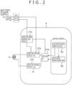
- FIG. 2 An example of a fuel injection control device configuration according to the present invention is shown in Fig. 2 .
- a block 27a includes a high-voltage generating circuit that generates, from a supply voltage of the battery of the internal combustion engine, a high supply voltage required for injector opening.
- the high supply voltage is supplied to a driving circuit 27d, which then generates a desired supply voltage using a dedicated command for supply voltage generation.
- a block 27b includes an injector driving circuit that selects either the high supply voltage for opening the injector, or a low supply voltage that is the battery supply voltage, and supplies the selected supply voltage to an injector 5.
- the injector 5 When the injector 5 is to be switched from a closed state to an open state, the block 27b supplies the high supply voltage (e.g., 65 V), thereby supplying an injector-opening current required for opening the injector.
- a block 27c switches the supply voltage to the battery voltage, thus supplying a hold current.
- a block 27c includes a driving circuit that is provided downstream of the injector, for supplying a driving current to the injector.
- the blocks 27c, 27b, 27a are controlled to be driven by the driving circuit of the block 27d, to supply the desired driving supply voltage and driving current to the injector.
- a driving period (power distribution duration to the injector) of the block 27d and the driving supply voltage value and driving current value thereof are controlled by commands that have been calculated in blocks 9a and 9b.
- the fuel injection control device optimizes the injector driving control quantity and fuel injection quantity required for combustion in the internal combustion engine.
- FIG. 3 An example of a driving circuit for the injector shown in Fig. 2 is shown in Fig. 3 .
- a high voltage for supplying the valve-opening current needed to open the injector is supplied from the high-voltage generating circuit via a diode, which prevents a backflow of the current, to the injector 5 by use of a TR_HiVboost circuit shown in the figure.
- a low voltage for supplying the hold current needed to maintain the open state of the injector is supplied from a low-voltage power supply circuit via a diode for preventing a backflow of the hold current, to the injector 5 by use of a TR_HiVb circuit shown in the figure.
- Composition of the high-voltage generating circuit here can be that of a generally known DC-DC converter or the like. Detailed description of this composition is omitted herein since the composition itself has no direct relationship with the present invention.
- the low voltage can likewise be the battery supply voltage itself of the internal combustion engine, and detailed description of the low voltage is likewise omitted herein.
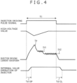
- Fig. 4 shows an example that represents a relationship between fuel injection pulse width, a profile of an injector driving current waveform, and internal opening/closing positions of the injector, in the present invention.
- Injector driving pulse signal TI shown in an upper section of Fig. 4 is a pulse signal based on the value which the block 9a in Fig. 2 has calculated.
- Middle and lower sections of Fig. 4 represent the relationship between the fuel injection pulse signal TI, the driving current flowing through the injector shown in the injector driving circuit of Figs. 2 and 3 , and the internal opening/closing positions of the injector; the lower section of Fig. 4 shows the profile of the injector driving current waveform.
- the driving IC 27d activates the driving circuits TR_Hivboost and TR_Low (both shown in Fig. 3 ) at the same time in synchronization with a rise of the pulse signal TI, and as shown in the middle section of Fig. 4 , supplies a valve-opening peak current Ip required for rapid valve-opening of the injector.
- the valve-opening current is supplied to the injector by the application of the high voltage from the high-voltage generating circuit.
- the high-voltage value shown in Fig. 4 decreases according to the amount of energy consumed as the valve-opening current for the injector, and after this decrease, the high-voltage generating circuit controls the high voltage to return to the desired value within a predetermined time.
- the driving IC 27d deactivates the driving circuit TR_Hivboost.
- the valve-opening current Ip is 11 A, for example.
- the driving circuit TR_Hivboost After the deactivation of the driving circuit TR_Hivboost following the arrival at the valve-opening current Ip, the current through the injector approaches a first target value Ih1 that is a level at which the current can maintain the injector in its open state.
- the driving IC 27d then activates the driving circuit TR_Hivb, thereby distributing the current from the low-voltage source to the injector.
- the driving circuit TR_Hivb is activated/deactivated to keep the current at the first target value Ih1, a level at which the valve-open state of the injector can be maintained.
- the first target value Ih1 is 5 A.
- the driving circuit TR_Hivb is activated/deactivated to keep the current at a second target value Ih2, another level at which the valve-open state of the injector can be maintained.
- the second target value Ih2 is 3 A.
- Timing in which the injector opens or closes depends on internal circuit operation of the fuel injection control device 27, a delay in a response of the current due to a harness leading to the injector 5, a magnetic force developed, and/or a delay in valve response.
- Td_OP response delay time
- Td_CL1 response delay time
- Fig. 5 shows another example that represents a relationship between pulse widths of fuel injection pulse signals, profiles of injector driving currents, and internal opening/closing positions of injectors, the example applying to a situation under which a plurality of injectors according to the present invention are adjacent to each other in driving timing.
- Behaviors denoted by a dotted line in Fig. 5 represent basic characteristics relating to the injector driving current waveform profile and injector's internal opening/closing positions described in Fig. 4 .
- control is conducted with the injectors of different cylinders being adjacent to each other in driving timing. This state is shown in Fig. 5 .
- the control conducted when fuel injection is repeated the plurality of times in one cylinder is intended for purposes such as ensuring stable idling of the internal combustion engine, early activating the catalyst, and reducing the amount of soot, that is, particulate matter (PM) released from exhaust. Detailed description of the particular control is therefore omitted herein.
- the valve-opening current for the injectors of an "m" number of cylinders in which the injection is started earlier than in an "n" number of cylinders (hereinafter, referred to simply as the n-cylinders) becomes gentle in growth rate, upon a start of driving of the n-cylinders, and the current behaves differently from the way it does during independent driving of one injector, denoted by a dotted line.
- a response delay time Td_OP of the m- and n-cylinders' injectors that is shown in a lower section of Fig. 5 delays behind (i.e., becomes longer than) the time described in Fig. 4 .
- the response delay time Td_OP differs according to a degree of the injectors' adjacency in terms of injection timing. The adjacency will be described in detail using Fig. 7 .
- Fig. 6 shows an example that represents injection flow characteristics obtained when the plurality of injectors according to the present invention are adjacent to each other in driving timing.
- a single-dotted line in Fig. 6 denotes the injection flow characteristics of one injector driven independently, unlike those of the plurality of injectors driven in adjacent timing as shown in Fig. 4 .
- Solid lines denote the m-cylinder injection characteristics and n-cylinder injection characteristics that are the injection flow characteristics of the m-cylinder and n-cylinder injectors, obtained when the plurality of injectors are adjacent to each other in driving timing as shown in Fig. 5 .
- the change in the valve-opening delay time Td_OP of the injector also changes the injection flow characteristics with respect to the injection pulse width. For example, at requested injection pulse width A (see Fig.
- a flow rate of the injected fuel takes a value of Qbase for the independent fuel injection characteristics, whereas those take values of Qm and Qn for the m-cylinder injection characteristics and n-cylinder injection characteristics, respectively.
- Qbase the quantity of injection
- Qbase the quantity of injection
- these fuel injection characteristics remain invariant in gradient (the gradient here represents a relationship of ⁇ injected-fuel flow rate/ ⁇ injection pulse width), and basically shift in a direction of the injection pulse width, i.e., in a direction of a horizontal axis in Fig. 6 .
- Fig. 7 shows an example that represents a relationship between flow characteristics of injectors and an air-fuel ratio in the internal combustion engine, the relationship being obtained when the plurality of injectors according to the present invention are adjacent to each other in driving timing.
- Fig. 7 The diagrams that represent the relationships in which, as shown in Figs. 5 and 6 , the differences in driving timing between a plurality of injectors affect the injection flow characteristics thereof, are described in further detail below using Fig. 7 .
- the "Simultaneous injection start" that is shown centrally in the figure denotes a position at which the injectors of a plurality of different cylinders have been driven in the same timing.
- the injected-fuel flow rate shown in a lower section of the figure changes with an injection starting time interval of the plurality of cylinders (m-cylinders and n-cylinders), that is plotted on a horizontal axis.
- fuel injection correction control for stabilized control of fuel injection requires changing the relationship in the relative position of the fuel injection driving start timing between a plurality of cylinders, and using the value that differs between the injector driven earlier and the injector driven later. Briefly, very complex control is required.
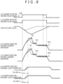
- Fig. 8 shows yet another example that represents a relationship between fuel injection pulse widths, profiles of injector driving currents, and internal opening/closing positions of injectors, the example applying to a situation under which a plurality of injectors according to the present invention are driven at the same time.
- FIG. 8 A total composition of Fig. 8 is the same as that of Fig. 5 , and description of the factors that constitute Fig. 8 is therefore omitted herein.
- the injectors in a plurality of cylinders are driven at the same time, there is no need to conduct the complex fuel-injection quantity correction control that as shown in Fig. 7 , requires correcting the relationship in the relative position of the fuel injection driving start timing between a plurality of cylinders, and also correcting the data that differs between the injector driven earlier and the injector driven later. Therefore, when a fuel injection driving timing request is made so that the relative positions of a plurality of cylinders in terms of the start timing of fuel injection driving will be adjacent within a predetermined data range (the predetermined data range here means a range in which the injected-fuel flow characteristics shown in Fig.
- the requested fuel injection driving timing can be changed to match to other adjacent start timing of fuel injection driving.
- the above change means changing the fuel injection driving timing only of one injector adjacent in terms of fuel injection timing, this injector being that of the cylinder which is more robust against combustion in the internal combustion engine.
- the fuel injection timing of the injector to inject the fuel into the cylinder in its intake stroke can be changed to conduct the control so that the fuel injection from this injector synchronizes with that of the injector for the cylinder in the compression stroke.
- Fig. 9 shows an example that represents timing charts relating to simultaneous driving timing of a plurality of injectors according to the present invention.
- pattern A at a left side relates to a case in which the plurality of injectors are relatively distant from each other in the start timing of fuel injection driving.
- Pattern B at a right side in Fig. 9 relates to a case in which the fuel injection driving of the injectors is started at the same time under a situation that the requested fuel injection driving timing is adjacent between the injectors. Whether the fuel injection timing is adjacent between the injectors of a plurality of cylinders can be discriminated by comparing ITANGH and ITANGS, which are angles from those standard angle positions for fuel injection timing control that are shown in Fig. 9 .
- the discrimination can be conducted using a value obtained by time-converting an angle value derived from an
- a factor involved when the high voltage from the high-voltage generating circuit is restored to a desired value is determined by time, not an angle of the internal combustion engine. The time-conversion therefore allows accurate discrimination.
- Fig. 10 shows an example of a restoration time of the high voltage generated by the high-voltage generating circuit as a voltage required for the valve-opening of the injectors according to the present invention.
- Fig. 10 is a relational diagram of the time required for the high-voltage generating circuit to restore the high supply voltage that has decreased as a result of electrical energy being consumed during injector driving, to the desired high-voltage value (say, 65 V).
- the restoration time differs according to the battery supply voltage required for the generation of the high voltage, and the valve-opening current Ip given by the injector which consumes the high voltage.
- the high-voltage restoration time exhibits a tendency to become longer as the battery voltage lowers or the valve-opening current Ip increases. Therefore, the time required for the high-voltage generating circuit to restore the high voltage shown in Fig. 9 , to the desired high-voltage value, can be calculated using either at least one of the battery voltage and the valve-opening current Ip given by the injector which consumes the high voltage, or both of the two parameters.
- Fig. 11 shows an example of fuel injection quantity correction control according to the present invention.
- Fig. 7 shows that the fact that the flow rate of the fuel injected varies with the multi-injector driving timing indicates that the valve-opening response time of the injector changes.
- accuracy of the fuel injection quantity correction control based on the injector pulse width can be improved by correcting invalid pulse width observed during the injector control (it is known that the method of controlling the injector here is by calculating the invalid pulse width in terms of valid pulse width + invalid pulse width, and further description of the invalid pulse width is therefore omitted herein).
- Fig. 11 shows correction characteristics of the invalid pulse width that assume a predetermined fuel pressure.
- both of the relationship in the relative position of the fuel injection driving start timing between the plurality of cylinders, and the quantity of fuel injection correction require correction with the value that differs between the injector driven earlier and the injector driven later, so the very complex fuel-injection quantity correction control described above is required.
- controlling the fuel injector driving timing of the plurality of cylinders at the same time allows this timing to be limited to the simultaneous injection starting point shown in the figure, and thereby, simple and accurate fuel injection quantity control to be implemented.
- the fuel pressure in the internal combustion engine has been conveniently shown as a constant pressure in Fig. 11 , conducting the fuel injection quantity correction appropriately according to the fuel pressure of the engine allows accurate fuel injection quantity control, even under a different fuel pressure state matching the particular operational state of the engine.
- Fig. 12 shows an example of a block diagram of injector control according to the present invention.
- Block 1201 calculates the fuel injection timing requirement (the ITANGH and ITANGS angles) matching the operational state of the internal combustion engine, the fuel pressure in the engine, and/or other parameters.
- block 1204 computes the valid pulse width of each injector from the operational state of the internal combustion engine, the fuel pressure in the engine, and/or other parameters.
- Block 1205 computes the invalid pulse width of the injector from the adjacent-timing information that was obtained in block 1202, then selects the computed invalid pulse width, and after adding the valid pulse width that was calculated in block 1204 to the invalid pulse width, outputs the invalid pulse width and the added valid pulse width in combined form. In this way, if the driving timing is adjacent between the injectors of the plurality of cylinders and the fuel injection quantity characteristic changes, accurate injector control can be achieved by simplifying the control circuit composition.
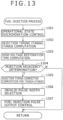
- Fig. 13 shows an example of a flowchart of injector control not covered by the present invention.
- Block 1301 determines the operational state of the internal combustion engine, and block 1302 calculates the injector-driving timing angle ITANGH, ITANGS from the operational state of the engine.
- Block 1303 calculates the restoration time of the injector-driving high voltage shown in Fig. 10 .
- Block 1304 uses the high-voltage restoration time calculation results in block 1303 to determine whether the driving timing is adjacent between the injectors of the plurality of cylinders. If the driving timing is determined to be adjacent, block 1305 corrects the driving timing to match between the different injectors. At this time, the injector that is more robust against combustion (i.e., the injector whose value is to be changed from requested injection data) is corrected for simultaneous injection.
- the requested injection value of both injectors may be calculated/corrected at predetermined rates each (for simultaneous injection, the value may be corrected appropriately according to the combustion state of the internal combustion engine, by for example calculating an intermediate value of the calculated ITANGH and ITANGS angle requirements).
- block 1306 calculates the invalid pulse widths of the injectors that are required for simultaneous fuel injection, as shown in Figs. 11 and 12 , and selects the calculated values.
- Block 1307 outputs the fuel injection pulse based on both of the fuel injection driving timing that was corrected by block 1304, and the invalid pulse width that was calculated by block 1306. Correction control is thus executed.
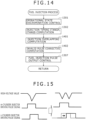
- Fig. 14 shows another example of a flowchart of injector control not covered by the present invention.
- This flowchart shows a control method effective for improving a situation in which the combustion in the internal combustion engine departs from a robustness range, by changing the fuel injection driving timing using the method shown in Fig. 13 not covered by the present invention.
- This flowchart shows details of the control process flow that was described in Fig. 7 as requiring complex control.
- Block 1401 calculates an overlapping time of the period during which the high voltage for opening the injector is consumed in a plurality of different cylinders.
- Block 1402 calculates, on a cylinder-by-cylinder basis, the invalid pulse width of the injector driven earlier in the fuel injection driving timing for the different cylinders that is adjacent to the overlapping time, and the invalid pulse width of the injector driven later. The correction of these invalid pulse widths is as shown in Fig. 11 .
- block 1307 adds each of the different invalid pulse widths correction value calculated for each injector by block 1402, to the valid pulse width of the injector. Block 1307 also outputs the injector pulse width data and provides injection control.
- This fuel-injection quantity control involves correcting the start timing of fuel injection driving and the invalid pulse width of the injector in accordance with the high-voltage value for opening the injector.
- the following describes another method of accurate fuel injection quantity control that does not require correcting the invalid pulse width of the injector, even when the requested injection driving starting timing is adjacent between different cylinders.
- Fig. 15 shows an example that represents fuel injection pulse width and high-voltage signal behavior for opening injectors in the present invention.
- FIG. 15 shows injector-driving pulse signal states and high-voltage changes in simplified form in the case that as described in detail in Fig. 5 , the requested fuel injection driving start timing is adjacent between different cylinders.
- the fact that these changes lead to changes in the fuel injection flow characteristics of each injector has also been described above.
- fuel can be injected without a change in the fuel injection flow characteristics of the injector, by as shown at a right side of Fig. 15 , providing the high-voltage restoration time interval in the driving timing differing between the injectors.
- the restoration time interval of the high voltage is as shown in Fig.
- the timing in which the driving of the injector is to be started is corrected through a time interval indicated by an arrow, with respect to the requested fuel injection driving start timing shown with a dotted line in the figure.
- the injector that is more combustion-robust i.e., the injector whose data is to be changed from requested injection data
- the interval equivalent to the restoration time may be obtained by calculating/correcting the requested injection data of both injectors at the predetermined respective rates (the value may be corrected appropriately according to the combustion state of the internal combustion engine, by for example, multiplying or adding/subtracting the calculated ITANGH and ITANGS angle requirements at the predetermined rates).
- Fig. 16 shows an example that illustrates a method of switching injector control in the case that the fuel injection driving timing is adjacent between the plurality of cylinders in the present invention.
- a solid line in Fig. 16 denotes how the fuel injection-driving timing correction value required for the simultaneous fuel injection shown in Fig. 13 varies when the fuel injection driving timing is adjacent between the plurality of cylinders. Fuel injection driving timing correction becomes necessary from within a range overlapping the restoration time of the high voltage, the fuel injection driving timing correction becomes a maximum, and at an angle position where the injectors are driven at the same time, the amount of correction becomes 0.
- the amount of fuel injection driving timing correction becomes line-symmetric about a central position at which the simultaneous injection start shown in the figure is achieved as the requested fuel-injection driving timing. If this fuel-injection driving timing correction affects the combustion in the internal combustion engine, regions A, B, C shown in the figure represent a degree of the influence. In region B, the fuel-injection driving timing correction does not affect the combustion in the engine since the amount of correction is small, and in regions A, C, the fuel-injection driving timing correction significantly affects the engine combustion since the amount of correction is large.
- a dotted line in Fig. 16 denotes how the correction of the fuel injection driving timing in Fig. 15 (i.e., avoidance of the high-voltage restoration time) changes the amount of correction.
- This change in the amount of correction unlike that shown with a solid line in the figure, becomes a maximum from within the range overlapping the restoration time of the high voltage, at the angle position where the injectors are driven at the same time, and the amount of fuel injection driving timing correction becomes line-symmetric similarly to the above.
- Fig. 17 shows a flowchart of injector control according to the present invention.
- Blocks 1301 to 1307 are as shown in Fig. 13 , and description of these blocks is herein omitted to avoid overlapping of the description.
- Block 1701 determines whether a difference in requested fuel-injection driving timing between a plurality of cylinders is within predetermined data range AA. If the predetermined data range is determined to be overstepped, block 1702 changes the fuel injection driving timing different between the injectors, in accordance with the high-voltage restoration time calculated in block 1303, the change being conducted to ensure the time required for the high voltage to return to the predetermined value. Details of the changing method are as described in Fig. 15 . The control method shown in Fig. 13 is conducted if, in block 1701, the difference in requested fuel-injection driving timing between the cylinders is determined to be within predetermined data range AA.
Landscapes
- Engineering & Computer Science (AREA)
- Chemical & Material Sciences (AREA)
- Combustion & Propulsion (AREA)
- Mechanical Engineering (AREA)
- General Engineering & Computer Science (AREA)
- Electrical Control Of Air Or Fuel Supplied To Internal-Combustion Engine (AREA)
- Fuel-Injection Apparatus (AREA)
Claims (2)
- Kraftstoffeinspritzsteuervorrichtung (27) für einen Verbrennungsmotor (1), umfassend:eine Hochspannungserzeugungsschaltung (27a) zum Erzeugen einer Hochspannung, die eine Batteriespannung überschreitet, die eine Spannung zum Antreiben einer Einspritzvorrichtung (5) ist, die Kraftstoff in einen Zylinder des Verbrennungsmotors (1) einspritzt, wobei die Batteriespannung und die Hochspannung verwendet werden, um der Einspritzvorrichtung (5) einen Haltestrom (Ih) sowie einen Ventilöffnungsstrom (Ip) als einen Antriebsstrom zuzuführen,wobei die Kraftstoffeinspritzsteuervorrichtung (27) konfiguriert ist,ein Kraftstoffeinspritzimpulssignal an die Einspritzvorrichtung (5) in einer Mehrzahl von Kraftstoffeinspritzzeitpunkten während eines Verbrennungszyklus auszugeben, undeine Wiederherstellungszeit zu berechnen, die für die Hochspannungserzeugungsschaltung (27a) erforderlich ist, um die Hochspannung auf einen vorbestimmten Wert wiederherzustellen, nachdem die Hochspannung durch das Antreiben der Einspritzvorrichtung (5) verbraucht wurde und abnimmt, undwenn die Einspritzung von Kraftstoff durch eine beliebige andere Einspritzvorrichtung (5) in einen anderen Zylinder des Verbrennungsmotors während der berechneten Wiederherstellungszeit angefordert wird, zu prüfen, ob eine Differenz zwischen dem angeforderten Kraftstoffeinspritzzeitpunkt der Einspritzvorrichtung (5) und dem angeforderten Kraftstoffeinspritzzeitpunkt der anderen Einspritzvorrichtung (5) innerhalb eines vorbestimmten Datenbereichs (AA) liegt oder nicht, und die Einspritzvorrichtung zwischen beiden Einspritzvorrichtungen zu identifizieren, wo die Kraftstoffeinspritzung weniger Einfluss auf die Verbrennung im Verbrennungsmotor (1) hat, wobeidie Kraftstoffeinspritzsteuervorrichtung (27) ferner konfiguriert ist, den Beginn des Kraftstoffeinspritzzeitpunkts der identifizierten Einspritzvorrichtung zu korrigieren, um die Kraftstoffeinspritzung durch die Einspritzvorrichtung (5) und die andere Einspritzvorrichtung (5) in den Zylinder und den anderen Zylinder gleichzeitig auszuführen, während die Einspritzdauer der Einspritzvorrichtung (5) und der anderen Einspritzvorrichtung (5) zum Kompensieren der gleichzeitigen Einspritzung angepasst wird, und wobeidie Differenz außerhalb des vorbestimmten Datenbereichs (AA) liegt,die Kraftstoffeinspritzsteuervorrichtung (27) ferner konfiguriert ist, den Beginn des Kraftstoffeinspritzzeitpunkts der identifizierten Einspritzvorrichtung (5) zu korrigieren, so dass die berechnete Wiederherstellungszeit zwischen den Kraftstoffeinspritzzeitpunkten der Einspritzvorrichtung (5) und der anderen Einspritzvorrichtung (5) bereitgestellt wird.
- Kraftstoffeinspritzsteuervorrichtung (27) nach Anspruch 1, wobei eine Schaltung zum Berechnen der Wiederherstellungszeit der Hochspannung die Berechnung basierend auf entweder mindestens einem von der Batteriespannung und dem Ventilöffnungsstrom (Ip) für die Einspritzvorrichtung (5) oder beiden davon durchführt.
Applications Claiming Priority (1)
| Application Number | Priority Date | Filing Date | Title |
|---|---|---|---|
| JP2011244079A JP5838074B2 (ja) | 2011-11-08 | 2011-11-08 | 内燃機関の燃料噴射制御装置 |
Publications (3)
| Publication Number | Publication Date |
|---|---|
| EP2592256A2 EP2592256A2 (de) | 2013-05-15 |
| EP2592256A3 EP2592256A3 (de) | 2018-09-19 |
| EP2592256B1 true EP2592256B1 (de) | 2024-06-05 |
Family
ID=47226000
Family Applications (1)
| Application Number | Title | Priority Date | Filing Date |
|---|---|---|---|
| EP12191863.5A Active EP2592256B1 (de) | 2011-11-08 | 2012-11-08 | Vorrichtung zur steuerung der kraftstoffeinspritzung für einen verbrennungsmotor |
Country Status (4)
| Country | Link |
|---|---|
| US (1) | US20130112172A1 (de) |
| EP (1) | EP2592256B1 (de) |
| JP (1) | JP5838074B2 (de) |
| CN (1) | CN103089470B (de) |
Families Citing this family (15)
| Publication number | Priority date | Publication date | Assignee | Title |
|---|---|---|---|---|
| JP2010255444A (ja) * | 2009-04-21 | 2010-11-11 | Hitachi Automotive Systems Ltd | 内燃機関の燃料噴射制御装置及び方法 |
| DE102012218370B4 (de) * | 2012-10-09 | 2015-04-02 | Continental Automotive Gmbh | Verfahren und Vorrichtung zum Steuern eines Ventils |
| JP5772884B2 (ja) * | 2013-06-24 | 2015-09-02 | トヨタ自動車株式会社 | 燃料噴射弁駆動システム |
| KR101509958B1 (ko) * | 2013-10-30 | 2015-04-08 | 현대자동차주식회사 | 인젝터 특성 보정 장치 |
| DE102014200184A1 (de) * | 2014-01-09 | 2015-07-09 | Robert Bosch Gmbh | Verfahren und Schaltungsanordnung zur Ansteuerung von Einspritzventilen, insbesondere einer fremdgezündeten Brennkraftmaschine |
| JP2015218614A (ja) * | 2014-05-15 | 2015-12-07 | トヨタ自動車株式会社 | 内燃機関の燃料噴射制御装置 |
| DE102014221706A1 (de) * | 2014-10-24 | 2016-04-28 | Robert Bosch Gmbh | Verfahren zur Bestromung eines Magnetventils eines Kraftstoffinjektors |
| EP3670880A1 (de) | 2014-11-19 | 2020-06-24 | Hitachi Automotive Systems, Ltd. | Antriebsvorrichtung für eine kraftstoffeinspritzvorrichtung |
| JP6393346B2 (ja) * | 2015-02-05 | 2018-09-19 | 日立オートモティブシステムズ株式会社 | 内燃機関の制御装置 |
| JP6581420B2 (ja) * | 2015-07-31 | 2019-09-25 | 日立オートモティブシステムズ株式会社 | 燃料噴射装置の制御装置 |
| EP3165749A1 (de) * | 2015-11-04 | 2017-05-10 | GE Jenbacher GmbH & Co. OG | Brennkraftmaschine mit einspritzmengensteuerung |
| EP3165750A1 (de) * | 2015-11-04 | 2017-05-10 | GE Jenbacher GmbH & Co. OG | Brennkraftmaschine mit kraftstoffinjektordiagnose |
| US10666129B2 (en) * | 2016-03-30 | 2020-05-26 | Hitachi Automotive Systems, Ltd. | Control Circuit |
| JP6751654B2 (ja) * | 2016-11-14 | 2020-09-09 | 日立オートモティブシステムズ株式会社 | 燃料噴射装置の制御装置 |
| US11946430B2 (en) | 2021-12-22 | 2024-04-02 | Caterpillar Inc. | Optimized energy waveform for fuel injector trimming based on valve arrival time |
Citations (1)
| Publication number | Priority date | Publication date | Assignee | Title |
|---|---|---|---|---|
| DE19752638A1 (de) * | 1996-11-28 | 1998-06-04 | Zexel Corp | Kraftstoffeinspritz-Steuersystem |
Family Cites Families (16)
| Publication number | Priority date | Publication date | Assignee | Title |
|---|---|---|---|---|
| US4688536A (en) * | 1985-06-28 | 1987-08-25 | Toyota Jidosha Kabushiki Kaisha | Drive circuit for an electrostrictive actuator in a fuel injection valve |
| JPH09177589A (ja) * | 1995-12-27 | 1997-07-08 | Mitsubishi Electric Corp | 内燃機関の筒内噴射式燃料制御装置 |
| JP3427683B2 (ja) * | 1997-07-24 | 2003-07-22 | 日産自動車株式会社 | 内燃機関の燃料供給装置 |
| US5957111A (en) * | 1998-03-16 | 1999-09-28 | Caterpillar Inc. | Method of regulating supply pressure in a hydraulically-actuated system |
| DE19813138A1 (de) * | 1998-03-25 | 1999-09-30 | Bosch Gmbh Robert | Verfahren und Vorrichtung zur Ansteuerung eines elektromagnetischen Verbrauchers |
| JP3575370B2 (ja) | 2000-01-26 | 2004-10-13 | トヨタ自動車株式会社 | 内燃機関の燃料噴射装置 |
| JP2002013430A (ja) * | 2000-06-29 | 2002-01-18 | Denso Corp | 筒内噴射式内燃機関の触媒早期暖機制御装置 |
| DE10033343A1 (de) * | 2000-07-08 | 2002-01-17 | Bosch Gmbh Robert | Kraftstoffeinspritzanlage für einen Verbrennungsmotor |
| JP2002206446A (ja) | 2001-01-10 | 2002-07-26 | Hitachi Ltd | 内燃機関及び内燃機関の燃料噴射制御装置 |
| DE10215630A1 (de) * | 2002-04-09 | 2003-10-30 | Bosch Gmbh Robert | Kraftstoffeinspritzanlage für einen Verbrennungsmotor und Verfahren zum Betrieb einer Kraftstoffeinspritzanlage |
| JP4148127B2 (ja) * | 2003-12-12 | 2008-09-10 | 株式会社デンソー | 燃料噴射装置 |
| JP4032356B2 (ja) * | 2004-04-14 | 2008-01-16 | 株式会社デンソー | 燃料噴射装置 |
| JP2008190388A (ja) * | 2007-02-02 | 2008-08-21 | Denso Corp | 電磁弁駆動装置及び燃料噴射制御装置 |
| DE102007005361B3 (de) * | 2007-02-02 | 2008-10-09 | Continental Automotive Gmbh | Vorrichtung und Verfahren zur Steuerung der Kraftstoffeinspritzung |
| JP4776651B2 (ja) * | 2008-03-28 | 2011-09-21 | 日立オートモティブシステムズ株式会社 | 内燃機関制御装置 |
| JP5198496B2 (ja) * | 2010-03-09 | 2013-05-15 | 日立オートモティブシステムズ株式会社 | 内燃機関のエンジンコントロールユニット |
-
2011
- 2011-11-08 JP JP2011244079A patent/JP5838074B2/ja active Active
-
2012
- 2012-11-06 US US13/669,963 patent/US20130112172A1/en not_active Abandoned
- 2012-11-07 CN CN201210441494.8A patent/CN103089470B/zh active Active
- 2012-11-08 EP EP12191863.5A patent/EP2592256B1/de active Active
Patent Citations (1)
| Publication number | Priority date | Publication date | Assignee | Title |
|---|---|---|---|---|
| DE19752638A1 (de) * | 1996-11-28 | 1998-06-04 | Zexel Corp | Kraftstoffeinspritz-Steuersystem |
Also Published As
| Publication number | Publication date |
|---|---|
| JP2013100748A (ja) | 2013-05-23 |
| EP2592256A2 (de) | 2013-05-15 |
| CN103089470A (zh) | 2013-05-08 |
| CN103089470B (zh) | 2016-08-17 |
| JP5838074B2 (ja) | 2015-12-24 |
| US20130112172A1 (en) | 2013-05-09 |
| EP2592256A3 (de) | 2018-09-19 |
Similar Documents
| Publication | Publication Date | Title |
|---|---|---|
| EP2592256B1 (de) | Vorrichtung zur steuerung der kraftstoffeinspritzung für einen verbrennungsmotor | |
| US8280613B2 (en) | Control apparatus for internal combustion engine | |
| US7778765B2 (en) | Fuel injection control apparatus for internal combustion engine | |
| US9835105B2 (en) | Fuel injection control device for internal combustion engine | |
| JP5982062B2 (ja) | 内燃機関の制御装置 | |
| US20100263632A1 (en) | Control Apparatus and Control Method for Internal Combustion Engine | |
| CN101397944B (zh) | 内燃机控制设备 | |
| US20090071443A1 (en) | Fuel Injection Control Apparatus for Internal Combustion Engine | |
| JP6157889B2 (ja) | 燃料噴射弁の制御装置 | |
| JP4462018B2 (ja) | エンジン制御システム | |
| JP7283418B2 (ja) | 内燃機関の燃料噴射制御装置 | |
| US20120136555A1 (en) | Fuel Injection Control Apparatus For Internal Combustion Engine | |
| US20150112576A1 (en) | Pump control apparatus for fuel supply system of fuel-injection engine | |
| US20160003182A1 (en) | Control Device for Internal Combustion Engine | |
| US9869263B2 (en) | Method of controlling a solenoid valve | |
| JP2013137028A (ja) | 内燃機関の燃料噴射制御装置及び方法 | |
| US10989123B2 (en) | Controller and control method for internal combustion engine | |
| JP7035466B2 (ja) | 燃料噴射制御装置 | |
| US11286873B2 (en) | Control device | |
| CN115698494B (zh) | 燃料喷射控制装置 | |
| US20200277915A1 (en) | Fuel injection control device and fuel injection control method | |
| CN113494380A (zh) | 用于控制内燃发动机的加燃料策略的方法和系统 | |
| JP2019039407A (ja) | 内燃機関の制御装置 |
Legal Events
| Date | Code | Title | Description |
|---|---|---|---|
| PUAI | Public reference made under article 153(3) epc to a published international application that has entered the european phase |
Free format text: ORIGINAL CODE: 0009012 |
|
| 17P | Request for examination filed |
Effective date: 20130215 |
|
| AK | Designated contracting states |
Kind code of ref document: A2 Designated state(s): AL AT BE BG CH CY CZ DE DK EE ES FI FR GB GR HR HU IE IS IT LI LT LU LV MC MK MT NL NO PL PT RO RS SE SI SK SM TR |
|
| AX | Request for extension of the european patent |
Extension state: BA ME |
|
| PUAL | Search report despatched |
Free format text: ORIGINAL CODE: 0009013 |
|
| AK | Designated contracting states |
Kind code of ref document: A3 Designated state(s): AL AT BE BG CH CY CZ DE DK EE ES FI FR GB GR HR HU IE IS IT LI LT LU LV MC MK MT NL NO PL PT RO RS SE SI SK SM TR |
|
| AX | Request for extension of the european patent |
Extension state: BA ME |
|
| RIC1 | Information provided on ipc code assigned before grant |
Ipc: F02D 41/20 20060101AFI20180814BHEP Ipc: F02D 41/40 20060101ALI20180814BHEP Ipc: F02D 41/34 20060101ALI20180814BHEP |
|
| STAA | Information on the status of an ep patent application or granted ep patent |
Free format text: STATUS: REQUEST FOR EXAMINATION WAS MADE |
|
| RAP3 | Party data changed (applicant data changed or rights of an application transferred) |
Owner name: HITACHI ASTEMO, LTD. |
|
| STAA | Information on the status of an ep patent application or granted ep patent |
Free format text: STATUS: EXAMINATION IS IN PROGRESS |
|
| 17Q | First examination report despatched |
Effective date: 20220408 |
|
| GRAP | Despatch of communication of intention to grant a patent |
Free format text: ORIGINAL CODE: EPIDOSNIGR1 |
|
| STAA | Information on the status of an ep patent application or granted ep patent |
Free format text: STATUS: GRANT OF PATENT IS INTENDED |
|
| INTG | Intention to grant announced |
Effective date: 20240326 |
|
| GRAS | Grant fee paid |
Free format text: ORIGINAL CODE: EPIDOSNIGR3 |
|
| GRAA | (expected) grant |
Free format text: ORIGINAL CODE: 0009210 |
|
| STAA | Information on the status of an ep patent application or granted ep patent |
Free format text: STATUS: THE PATENT HAS BEEN GRANTED |
|
| AK | Designated contracting states |
Kind code of ref document: B1 Designated state(s): AL AT BE BG CH CY CZ DE DK EE ES FI FR GB GR HR HU IE IS IT LI LT LU LV MC MK MT NL NO PL PT RO RS SE SI SK SM TR |
|
| REG | Reference to a national code |
Ref country code: GB Ref legal event code: FG4D |
|
| REG | Reference to a national code |
Ref country code: CH Ref legal event code: EP |
|
| REG | Reference to a national code |
Ref country code: DE Ref legal event code: R096 Ref document number: 602012080837 Country of ref document: DE |
|
| REG | Reference to a national code |
Ref country code: IE Ref legal event code: FG4D |
|
| REG | Reference to a national code |
Ref country code: LT Ref legal event code: MG9D |
|
| PG25 | Lapsed in a contracting state [announced via postgrant information from national office to epo] |
Ref country code: BG Free format text: LAPSE BECAUSE OF FAILURE TO SUBMIT A TRANSLATION OF THE DESCRIPTION OR TO PAY THE FEE WITHIN THE PRESCRIBED TIME-LIMIT Effective date: 20240605 |
|
| REG | Reference to a national code |
Ref country code: NL Ref legal event code: MP Effective date: 20240605 |
|
| PG25 | Lapsed in a contracting state [announced via postgrant information from national office to epo] |
Ref country code: HR Free format text: LAPSE BECAUSE OF FAILURE TO SUBMIT A TRANSLATION OF THE DESCRIPTION OR TO PAY THE FEE WITHIN THE PRESCRIBED TIME-LIMIT Effective date: 20240605 Ref country code: FI Free format text: LAPSE BECAUSE OF FAILURE TO SUBMIT A TRANSLATION OF THE DESCRIPTION OR TO PAY THE FEE WITHIN THE PRESCRIBED TIME-LIMIT Effective date: 20240605 |
|
| PG25 | Lapsed in a contracting state [announced via postgrant information from national office to epo] |
Ref country code: GR Free format text: LAPSE BECAUSE OF FAILURE TO SUBMIT A TRANSLATION OF THE DESCRIPTION OR TO PAY THE FEE WITHIN THE PRESCRIBED TIME-LIMIT Effective date: 20240906 |
|
| PG25 | Lapsed in a contracting state [announced via postgrant information from national office to epo] |
Ref country code: ES Free format text: LAPSE BECAUSE OF FAILURE TO SUBMIT A TRANSLATION OF THE DESCRIPTION OR TO PAY THE FEE WITHIN THE PRESCRIBED TIME-LIMIT Effective date: 20240605 |
|
| PG25 | Lapsed in a contracting state [announced via postgrant information from national office to epo] |
Ref country code: LV Free format text: LAPSE BECAUSE OF FAILURE TO SUBMIT A TRANSLATION OF THE DESCRIPTION OR TO PAY THE FEE WITHIN THE PRESCRIBED TIME-LIMIT Effective date: 20240605 |
|
| PG25 | Lapsed in a contracting state [announced via postgrant information from national office to epo] |
Ref country code: NO Free format text: LAPSE BECAUSE OF FAILURE TO SUBMIT A TRANSLATION OF THE DESCRIPTION OR TO PAY THE FEE WITHIN THE PRESCRIBED TIME-LIMIT Effective date: 20240905 Ref country code: LV Free format text: LAPSE BECAUSE OF FAILURE TO SUBMIT A TRANSLATION OF THE DESCRIPTION OR TO PAY THE FEE WITHIN THE PRESCRIBED TIME-LIMIT Effective date: 20240605 Ref country code: HR Free format text: LAPSE BECAUSE OF FAILURE TO SUBMIT A TRANSLATION OF THE DESCRIPTION OR TO PAY THE FEE WITHIN THE PRESCRIBED TIME-LIMIT Effective date: 20240605 Ref country code: GR Free format text: LAPSE BECAUSE OF FAILURE TO SUBMIT A TRANSLATION OF THE DESCRIPTION OR TO PAY THE FEE WITHIN THE PRESCRIBED TIME-LIMIT Effective date: 20240906 Ref country code: FI Free format text: LAPSE BECAUSE OF FAILURE TO SUBMIT A TRANSLATION OF THE DESCRIPTION OR TO PAY THE FEE WITHIN THE PRESCRIBED TIME-LIMIT Effective date: 20240605 Ref country code: ES Free format text: LAPSE BECAUSE OF FAILURE TO SUBMIT A TRANSLATION OF THE DESCRIPTION OR TO PAY THE FEE WITHIN THE PRESCRIBED TIME-LIMIT Effective date: 20240605 Ref country code: BG Free format text: LAPSE BECAUSE OF FAILURE TO SUBMIT A TRANSLATION OF THE DESCRIPTION OR TO PAY THE FEE WITHIN THE PRESCRIBED TIME-LIMIT Effective date: 20240605 Ref country code: RS Free format text: LAPSE BECAUSE OF FAILURE TO SUBMIT A TRANSLATION OF THE DESCRIPTION OR TO PAY THE FEE WITHIN THE PRESCRIBED TIME-LIMIT Effective date: 20240905 |
|
| PG25 | Lapsed in a contracting state [announced via postgrant information from national office to epo] |
Ref country code: NL Free format text: LAPSE BECAUSE OF FAILURE TO SUBMIT A TRANSLATION OF THE DESCRIPTION OR TO PAY THE FEE WITHIN THE PRESCRIBED TIME-LIMIT Effective date: 20240605 |
|
| REG | Reference to a national code |
Ref country code: AT Ref legal event code: MK05 Ref document number: 1692616 Country of ref document: AT Kind code of ref document: T Effective date: 20240605 |
|
| PG25 | Lapsed in a contracting state [announced via postgrant information from national office to epo] |
Ref country code: NL Free format text: LAPSE BECAUSE OF FAILURE TO SUBMIT A TRANSLATION OF THE DESCRIPTION OR TO PAY THE FEE WITHIN THE PRESCRIBED TIME-LIMIT Effective date: 20240605 |
|
| PG25 | Lapsed in a contracting state [announced via postgrant information from national office to epo] |
Ref country code: PT Free format text: LAPSE BECAUSE OF FAILURE TO SUBMIT A TRANSLATION OF THE DESCRIPTION OR TO PAY THE FEE WITHIN THE PRESCRIBED TIME-LIMIT Effective date: 20241007 |
|
| PG25 | Lapsed in a contracting state [announced via postgrant information from national office to epo] |
Ref country code: PT Free format text: LAPSE BECAUSE OF FAILURE TO SUBMIT A TRANSLATION OF THE DESCRIPTION OR TO PAY THE FEE WITHIN THE PRESCRIBED TIME-LIMIT Effective date: 20241007 |
|
| PG25 | Lapsed in a contracting state [announced via postgrant information from national office to epo] |
Ref country code: PL Free format text: LAPSE BECAUSE OF FAILURE TO SUBMIT A TRANSLATION OF THE DESCRIPTION OR TO PAY THE FEE WITHIN THE PRESCRIBED TIME-LIMIT Effective date: 20240605 |
|
| PG25 | Lapsed in a contracting state [announced via postgrant information from national office to epo] |
Ref country code: EE Free format text: LAPSE BECAUSE OF FAILURE TO SUBMIT A TRANSLATION OF THE DESCRIPTION OR TO PAY THE FEE WITHIN THE PRESCRIBED TIME-LIMIT Effective date: 20240605 |
|
| PG25 | Lapsed in a contracting state [announced via postgrant information from national office to epo] |
Ref country code: IS Free format text: LAPSE BECAUSE OF FAILURE TO SUBMIT A TRANSLATION OF THE DESCRIPTION OR TO PAY THE FEE WITHIN THE PRESCRIBED TIME-LIMIT Effective date: 20241005 Ref country code: AT Free format text: LAPSE BECAUSE OF FAILURE TO SUBMIT A TRANSLATION OF THE DESCRIPTION OR TO PAY THE FEE WITHIN THE PRESCRIBED TIME-LIMIT Effective date: 20240605 |
|
| PG25 | Lapsed in a contracting state [announced via postgrant information from national office to epo] |
Ref country code: CZ Free format text: LAPSE BECAUSE OF FAILURE TO SUBMIT A TRANSLATION OF THE DESCRIPTION OR TO PAY THE FEE WITHIN THE PRESCRIBED TIME-LIMIT Effective date: 20240605 |
|
| PG25 | Lapsed in a contracting state [announced via postgrant information from national office to epo] |
Ref country code: RO Free format text: LAPSE BECAUSE OF FAILURE TO SUBMIT A TRANSLATION OF THE DESCRIPTION OR TO PAY THE FEE WITHIN THE PRESCRIBED TIME-LIMIT Effective date: 20240605 Ref country code: SK Free format text: LAPSE BECAUSE OF FAILURE TO SUBMIT A TRANSLATION OF THE DESCRIPTION OR TO PAY THE FEE WITHIN THE PRESCRIBED TIME-LIMIT Effective date: 20240605 |
|
| PG25 | Lapsed in a contracting state [announced via postgrant information from national office to epo] |
Ref country code: SM Free format text: LAPSE BECAUSE OF FAILURE TO SUBMIT A TRANSLATION OF THE DESCRIPTION OR TO PAY THE FEE WITHIN THE PRESCRIBED TIME-LIMIT Effective date: 20240605 |
|
| PG25 | Lapsed in a contracting state [announced via postgrant information from national office to epo] |
Ref country code: SM Free format text: LAPSE BECAUSE OF FAILURE TO SUBMIT A TRANSLATION OF THE DESCRIPTION OR TO PAY THE FEE WITHIN THE PRESCRIBED TIME-LIMIT Effective date: 20240605 Ref country code: SK Free format text: LAPSE BECAUSE OF FAILURE TO SUBMIT A TRANSLATION OF THE DESCRIPTION OR TO PAY THE FEE WITHIN THE PRESCRIBED TIME-LIMIT Effective date: 20240605 Ref country code: RO Free format text: LAPSE BECAUSE OF FAILURE TO SUBMIT A TRANSLATION OF THE DESCRIPTION OR TO PAY THE FEE WITHIN THE PRESCRIBED TIME-LIMIT Effective date: 20240605 Ref country code: PL Free format text: LAPSE BECAUSE OF FAILURE TO SUBMIT A TRANSLATION OF THE DESCRIPTION OR TO PAY THE FEE WITHIN THE PRESCRIBED TIME-LIMIT Effective date: 20240605 Ref country code: IS Free format text: LAPSE BECAUSE OF FAILURE TO SUBMIT A TRANSLATION OF THE DESCRIPTION OR TO PAY THE FEE WITHIN THE PRESCRIBED TIME-LIMIT Effective date: 20241005 Ref country code: EE Free format text: LAPSE BECAUSE OF FAILURE TO SUBMIT A TRANSLATION OF THE DESCRIPTION OR TO PAY THE FEE WITHIN THE PRESCRIBED TIME-LIMIT Effective date: 20240605 Ref country code: CZ Free format text: LAPSE BECAUSE OF FAILURE TO SUBMIT A TRANSLATION OF THE DESCRIPTION OR TO PAY THE FEE WITHIN THE PRESCRIBED TIME-LIMIT Effective date: 20240605 Ref country code: AT Free format text: LAPSE BECAUSE OF FAILURE TO SUBMIT A TRANSLATION OF THE DESCRIPTION OR TO PAY THE FEE WITHIN THE PRESCRIBED TIME-LIMIT Effective date: 20240605 |
|
| PG25 | Lapsed in a contracting state [announced via postgrant information from national office to epo] |
Ref country code: IT Free format text: LAPSE BECAUSE OF FAILURE TO SUBMIT A TRANSLATION OF THE DESCRIPTION OR TO PAY THE FEE WITHIN THE PRESCRIBED TIME-LIMIT Effective date: 20240605 |
|
| REG | Reference to a national code |
Ref country code: DE Ref legal event code: R097 Ref document number: 602012080837 Country of ref document: DE |
|
| PLBE | No opposition filed within time limit |
Free format text: ORIGINAL CODE: 0009261 |
|
| STAA | Information on the status of an ep patent application or granted ep patent |
Free format text: STATUS: NO OPPOSITION FILED WITHIN TIME LIMIT |
|
| PG25 | Lapsed in a contracting state [announced via postgrant information from national office to epo] |
Ref country code: DK Free format text: LAPSE BECAUSE OF FAILURE TO SUBMIT A TRANSLATION OF THE DESCRIPTION OR TO PAY THE FEE WITHIN THE PRESCRIBED TIME-LIMIT Effective date: 20240605 |
|
| 26N | No opposition filed |
Effective date: 20250306 |
|
| REG | Reference to a national code |
Ref country code: CH Ref legal event code: PL |
|
| PG25 | Lapsed in a contracting state [announced via postgrant information from national office to epo] |
Ref country code: MC Free format text: LAPSE BECAUSE OF FAILURE TO SUBMIT A TRANSLATION OF THE DESCRIPTION OR TO PAY THE FEE WITHIN THE PRESCRIBED TIME-LIMIT Effective date: 20240605 |
|
| PG25 | Lapsed in a contracting state [announced via postgrant information from national office to epo] |
Ref country code: LU Free format text: LAPSE BECAUSE OF NON-PAYMENT OF DUE FEES Effective date: 20241108 |
|
| REG | Reference to a national code |
Ref country code: CH Ref legal event code: PL |
|
| GBPC | Gb: european patent ceased through non-payment of renewal fee |
Effective date: 20241108 |
|
| PG25 | Lapsed in a contracting state [announced via postgrant information from national office to epo] |
Ref country code: CH Free format text: LAPSE BECAUSE OF NON-PAYMENT OF DUE FEES Effective date: 20241130 |
|
| REG | Reference to a national code |
Ref country code: BE Ref legal event code: MM Effective date: 20241130 |
|
| PG25 | Lapsed in a contracting state [announced via postgrant information from national office to epo] |
Ref country code: SE Free format text: LAPSE BECAUSE OF FAILURE TO SUBMIT A TRANSLATION OF THE DESCRIPTION OR TO PAY THE FEE WITHIN THE PRESCRIBED TIME-LIMIT Effective date: 20240605 |
|
| PG25 | Lapsed in a contracting state [announced via postgrant information from national office to epo] |
Ref country code: GB Free format text: LAPSE BECAUSE OF NON-PAYMENT OF DUE FEES Effective date: 20241108 Ref country code: BE Free format text: LAPSE BECAUSE OF NON-PAYMENT OF DUE FEES Effective date: 20241130 |
|
| PG25 | Lapsed in a contracting state [announced via postgrant information from national office to epo] |
Ref country code: FR Free format text: LAPSE BECAUSE OF NON-PAYMENT OF DUE FEES Effective date: 20241130 |
|
| PG25 | Lapsed in a contracting state [announced via postgrant information from national office to epo] |
Ref country code: IE Free format text: LAPSE BECAUSE OF NON-PAYMENT OF DUE FEES Effective date: 20241108 |
|
| PGFP | Annual fee paid to national office [announced via postgrant information from national office to epo] |
Ref country code: DE Payment date: 20250930 Year of fee payment: 14 |
|
| PG25 | Lapsed in a contracting state [announced via postgrant information from national office to epo] |
Ref country code: HU Free format text: LAPSE BECAUSE OF FAILURE TO SUBMIT A TRANSLATION OF THE DESCRIPTION OR TO PAY THE FEE WITHIN THE PRESCRIBED TIME-LIMIT; INVALID AB INITIO Effective date: 20121108 |
|
| PG25 | Lapsed in a contracting state [announced via postgrant information from national office to epo] |
Ref country code: CY Free format text: LAPSE BECAUSE OF FAILURE TO SUBMIT A TRANSLATION OF THE DESCRIPTION OR TO PAY THE FEE WITHIN THE PRESCRIBED TIME-LIMIT; INVALID AB INITIO Effective date: 20121108 |