EP2592379A2 - Verfahren zur Bestimmung der Orientierung zweier über zwei Kreuzgelenke und eine dritte Welle verbundener Wellen in der Ebene der drei Wellen - Google Patents
Verfahren zur Bestimmung der Orientierung zweier über zwei Kreuzgelenke und eine dritte Welle verbundener Wellen in der Ebene der drei Wellen Download PDFInfo
- Publication number
- EP2592379A2 EP2592379A2 EP12191581.3A EP12191581A EP2592379A2 EP 2592379 A2 EP2592379 A2 EP 2592379A2 EP 12191581 A EP12191581 A EP 12191581A EP 2592379 A2 EP2592379 A2 EP 2592379A2
- Authority
- EP
- European Patent Office
- Prior art keywords
- shaft
- shafts
- measurement
- light beam
- plane
- Prior art date
- Legal status (The legal status is an assumption and is not a legal conclusion. Google has not performed a legal analysis and makes no representation as to the accuracy of the status listed.)
- Granted
Links
Images




Classifications
-
- G—PHYSICS
- G01—MEASURING; TESTING
- G01B—MEASURING LENGTH, THICKNESS OR SIMILAR LINEAR DIMENSIONS; MEASURING ANGLES; MEASURING AREAS; MEASURING IRREGULARITIES OF SURFACES OR CONTOURS
- G01B11/00—Measuring arrangements characterised by the use of optical techniques
- G01B11/26—Measuring arrangements characterised by the use of optical techniques for measuring angles or tapers; for testing the alignment of axes
- G01B11/27—Measuring arrangements characterised by the use of optical techniques for measuring angles or tapers; for testing the alignment of axes for testing the alignment of axes
- G01B11/272—Measuring arrangements characterised by the use of optical techniques for measuring angles or tapers; for testing the alignment of axes for testing the alignment of axes using photoelectric detection means
Definitions
- the invention relates to an improved and simplified method for determining and correcting the angular offset of two shafts of machines or machine components which due to their parallel offset are connected to one another by way of two universal joints and a third shaft which connects the two universal joints.
- both the incidence position and also the incidence direction of a light beam can be measured by there being two detectors in succession in the beam path of the measurement head which can be read out two-dimensionally.
- This arrangement can be achieved, for example, via a beam splitter.
- measurement devices are also described in which one measurement head contains both a light source and also a two-dimensional detector, while the second measurement head contains a reflector, for example, in the form of a ridge prism.
- the alignment devices which are described in the aforementioned documents use light beams of point cross section and detectors which can be read out two-dimensionally.
- German Patent Application DE 10 2006 023 926 (which corresponds to U.S. Patent 7,672,001 ) describes alignment devices in which light beams are fanned out transversely relative to the propagation direction in more than one direction. Some embodiments call for each measurement head to contain both a light source and also a detector. The aforementioned optical alignment devices assume that the points of impact of the light beam or light beams on the detector or detectors is measured in several (at least three, but usually four or even five or more) rotary positions of the two shafts.
- German Patent DE 33 35 336 (which corresponds to U.S. Patent 4,518,855 ) describes an alignment device in which each measurement head contains both a light source and also detectors which can be read out two-dimensionally according to the site of incidence and angle of incidence.
- This measurement device is able to determine a misalignment according to angular and parallel offset in only one rotary position of the two shafts from one measurement of the points of impact on the detectors when the orientation of this rotary position and the points of impact are known for well aligned shafts by a comparison measurement on a single straight shaft. Measurements on the shafts which are to be aligned in different angular positions are, however, also fundamentally possible.
- the primary object of the present invention is to devise a method for determining the angular offset of two shafts which are connected via two universal joints and a third shaft, using an optical alignment device which makes superfluous the use of the aforementioned additional devices for measuring the angular offset of two shafts that are offset in parallel and which nevertheless enables high precision in the determination of the angular offset.
- Another object of the invention is to provide a simple and reliable method for determining the angular offset.
- the method for achieving these objects comprises the following steps:
- the determination of the angular offset is, in principle, possible with any of the indicated alignment devices from the aforementioned prior art.
- the measurement devices are made such that the holding devices which connect the measurement heads to the shafts are configured such that a change of the position of the measurement heads in the radial direction relative to the shaft is possible, as becomes apparent from the following description.
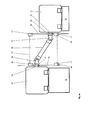
- Figure 1 is a perspective view of the device with two shafts and the connecting shaft with the two universal joints, and a schematic depiction of the alignment method with the optical alignment device.
- Figure 2a is a representation of the geometrical conditions, viewed horizontally, perpendicular to the axes of the two machine components
- Figure 2b is a representation of the geometrical conditions in a viewing direction along the axes of the two machine components
- Figure 2c is an overhead plan view of the geometrical conditions.
- Figure 3a shows the invention in conjunction with the optical alignment device, viewed horizontally perpendicular to the axes of the two machine components
- Figure 3b shows the invention in conjunction with the optical alignment device in a viewing direction along the axes of the two machine components
- Figure 3c shows the invention in conjunction with the optical alignment device in an overhead plan view.
- Figure 1 as well as Figures 2 and 3 show a first machine or machine component 30 with a shaft 34 on a first base 32 and a second machine or machine component 31 with a shaft 35 on a second base 33.
- the shafts of these two machines or machine components are essentially parallel in the orientation of their axes, but offset to one another in at least one of the two directions perpendicular to the axis direction of the two shafts. Therefore, on the ends of the shafts 34, 35 there is a respective universal joint 36, 37.
- the two universal joints 36, 37 are connected to one another using a third shaft 38.
- the steps a) to e) are established in accordance with the invention based on the finding that a measurement of the angular offset with a conventional optical alignment device in only two measurement positions is accurately possible when the two measurement heads of the alignment device are located in the plane formed by the three cardan shafts (see third "condition").
- a detector must be used which can be read out two-dimensionally.
- two light beams and two one-dimensional detectors it is also possible for two light beams and two one-dimensional detectors to be used when the two detectors run in different directions, therefore, for example, are arranged at a right angle to one another.
- the measurement heads 40, 41 can be arranged on their holding devices 45, 46 such that the light beam or beams 43 emitted from them run in the plane 71 which is formed by the two shafts 34, 35 and the connecting third shaft 38.
- the plane of this light beam will be perpendicular to the plane of the two shafts.
- the same angular position relative to the axes to be measured must always be approached.
- the devices which connect the measurement heads of the optoelectronic alignment devices which have been described in the prior art to the shafts which are to be aligned relative to one another.
- They ordinarily comprise a clamping device which provides for a fixed and rigid connection of the measurement head to the shaft.
- These clamping devices contain a body for placing against the jacket surface of a cylindrical shaft. This body is often a block 47, 48 with a prismatic recess.
- Such a block with a prismatic recess can be easily mounted on shafts of different diameters so that the apex line of the prismatic recess runs exactly parallel to the shaft axis.
- the fixed connection of the body to the shaft is produced by locking the block with the prismatic recess on the shaft.
- the carrier for a measurement head therefore comprises the clamping device for attachment to the shaft and a holding device for the measurement head, for example, rods, pipes, or the plates of U.S. Patent 4,518,855 , which is hereby incorporated by reference to the extent necessary to complete an understanding of this aspect of the invention..
- the body or block of the clamping device provides for a stable connection between the shaft, on which it is clamped, for example, with a chain, and the holding devices, therefore rods, pipes 45, 46 or alternatively the a V-block and strap device of U.S. Patent 4,518,855 .
- the invention is based on the following finding: only when the two measurement heads 40, 41 are located in the plane formed from the three shafts, therefore in two measurement positions offset by 180° in this plane, is a measurement possible. In these two positions, the position of the two measurement heads which has been measured peripherally (therefore in a direction perpendicular to the shaft axis and tangentially to the periphery of the shaft) is identical.
- Step a) Determining the plane of the three shafts.
- a clamping device with a measurement head 40 of an alignment device is located on the shaft 35.
- the measurement head 40 sends a light beam 43 in the direction to the second machine or machine component 31.
- the second machine or machine component 31 has a second shaft 35.
- a universal joint 36 is mounted on this shaft 35.
- a third shaft 38 connects the universal joint 36 to the second universal joint 37 on the shaft 35.
- the first measurement position can in principle be determined by geometrical plotting in an auxiliary plane 72 perpendicular to the plane 71 of the two shafts ( Figs. 2a , 2b ) by the point of impact of the laser beam on an end shield or another suitable flat surface, which is arranged on the shaft 35 to which the source of the light beam is not attached such that the normal of this flat surface runs in the direction of the axis of this shaft 35, being plotted in three angular positions of the transmitting device of the light beam.
- the three points of impact which have been determined in this way form a circle.
- This auxiliary plane 72 can be an end shield or a plate of a machine lining.
- this surface can be produced by placing a plane (for example, a piece of cardboard or a board) perpendicular to the shaft. Here, it must simply be watched that the light source used is easily visible on the plane.
- the first measurement position or the plane which is common to the shafts can be especially easily determined by direction finding along a line of sight of the drive shafts or driven shafts.
- the measurement head with the light source of this beam is mounted on the machine or machine component whose position in the alignment process cannot be changed.
- a complex machine has a pump, a fan or a roller with a driven shaft and a motor which drives the pump, the fan or the roller
- the position of the pump, the fan or the roller is normally stipulated, for example, by the disposition of the pipes or the path of the material transported on the roller.
- the position of the motor can, however, be changed in order to produce an optimum alignment according to the aforementioned two conditions.
- the alignment device has a light source in only one of the two measurement heads
- the measurement head with the light source is conventionally mounted on the shaft of the machine component which is not moving, therefore, the pump, fan or roller. This was originally fixed in this way because in correction of the position of one of the two machines when the measurement head with the light source is mounted on the machine which is being offset, especially for large measurement distances, an overly large offset between the measurement heads with light source and detector can occur, especially when the distance between the measurement heads is one meter or more.
- This attachment of the light source and detector is, however, also preferred in the measurement of two shafts which are connected via two universal joints and a third shaft, when only one of the measurement heads contains a light source.
- the shaft of the machine which cannot be offset and the third shaft which connects the universal joints fix the plane of the aforementioned third "condition.”
- the machine 30 with the shaft 34 was chosen to be stationary and the machine 31 with the shaft 35 was chosen to be movable.
- the measurement head 40, 40' which contains the light source is mounted on the shaft 34 of the stationary machine component 30.
- the light source is located radially relatively near the shaft 34
- the light beam strikes the third shaft 38 when the clamping device is suitably mounted.
- the clamping device is turned around the shaft 34 until the light beam strikes exactly the middle of the shaft 38.
- This middle of the shaft 38 is exactly the point along a peripheral line of the shaft or the line on the shaft 38 which the light beam describes in its (tangential) displacement along the periphery of the shaft 34 on which the measurement head 40' with its light source is attached, which head is nearest the light source. It is useful to check this alignment in another (radial) position of the measurement head 40'.
- This checking takes place by the measurement head being pushed along the holding device (here formed by two rods) in a direction which runs radially relative to the shaft 34. Then, the alignment of the clamping device on the shaft 34 is checked using the impact point of the light beam which has been emitted from the measurement head on the shaft 38 and is optionally corrected.
- the light source has the possibility of fine adjustment of the direction of the emitted light beam
- via ascertaining the impact site of the light beam which has been emitted from the measurement head 40' at positions of the measurement head 40' which are variously distant radially from the axis of the shaft 34 using the rotation of the clamping device around the shaft 34 and using the fine adjustment of the direction of the light beam an alignment of the measurement head 40' and of the light beam which has been emitted from the measurement head into the plane which is common to the three shafts and in a direction parallel to the axis of the shaft on which the measurement head is attached can be done very accurately.
- Another possibility for checking the alignment of the light source involves removing the measurement head from the rods after adjusting the emission direction and reattaching it to the rods in the reversed position (so-to-speak "headfirst") and in checking the alignment to the third shaft and optionally iteratively correcting it.
- the measurement head 40' is pushed along the rods away from the shaft 34 in the radial direction so far that the light beam emitted from this measurement head no longer strikes the third shaft 38, but the second measurement head 41' which is attached to the shaft 35.
- the measurement head 41' can accordingly be located on its rods opposite the measurement head 40' and is thus likewise in the plane formed from the three shafts 34, 35, 38.
- This type of determination of the plane 71 which has been formed by the three shafts 34, 35, 38 can be combined with the traditional procedure of attaching the light source to the fixed machine component 30 which cannot move because, in this way, the plane 71 is determined using the shaft 34 of the stationary machine component 30 and the third connecting shaft 38.
- the position of the movable component 31 is changed in the alignment process. This could, in turn, cause a change of the three-dimensional location of the plane of the three shafts if the shaft 35 of the movable component 31 were used to determine this plane.
- a light source other than the one contained in one of the measurement heads.
- a laser pointer can be used.
- a third type of determination of the plane of the three shafts 34, 35, 38 it is determined based on the geometrical circumstances. This takes place first by measuring the distance between the universal joints which can be determined, for example, by vertical projection of the shafts or their extensions on the floor of the hall. In this vertical projection, the measurement of the lateral distance of the shafts 34, 35 then takes place. Alternatively or additionally, measurement of the vertical difference between the two shafts is done depending on whether only one lateral or one vertical offset or both are present. If the angle of the plane relative to the vertical or horizontal has been determined in this way, using an inclinometer which can be present in one of the measurement heads 40, 41, the measurement head can be arranged on the shaft. This angle to the horizontal or vertical can, of course, also be taken from the construction data, for example, a drawing.
- Step b) Measurement of the impact position of the light beam or beams in the first measurement position. If the clamping device and the measurement head 40' are now aligned to the middle of the third shaft 38, at this point on the shaft 35 the second measurement head 41' with its clamping device is attached to the rods such that the angular position of the clamping device with the rods on the shaft 35 corresponds to the position found by step a) above for the clamping device mounted on the shaft 34 with the rods. This means that the rods 45', 46' of the two measurement heads 40', 41' can be aligned in parallel.
- the position of the impact point of the light beam or of the impact points of the light beams on the detector or detectors is measured and transmitted to a computer 63 which is used to evaluate the data which have been determined.
- a computer 63 which is used to evaluate the data which have been determined.
- the orientation of the measurement head 45' and 46' is known, for example, via an inclinometer which is present in this measurement head, it can also be transmitted to the computer and can be input into the computer by the user.
- Step c) Approaching the second measurement position, i.e., the position 180° from the first measurement position.
- the three shafts 34, 35, 38 are turned by 180° or the two clamping devices are displaced by 180° around the shafts.
- This measured value of the inclinometer is displayed on a computer 63 which is used to display the measured value of the alignment devices. It is also possible to compute this measured value with the measured value found by step b) above, and to show on the display of the computer 63 whether the measurement heads are, at this point, within a given region of the angle to be approached.
- Other suitable inclinometers are displayed on the measurement head itself and/or read off.
- inclinometers can be simple pointers with an angle scale.
- a rotation angle transducer on at least one of the two shafts 34, 35 can also be used, if it is present and its measured value is available in the determination of the alignment. Due to the still unknown misalignment, it is also possible, but not so exactly, to attach the light source or the measurement head with the light source after approaching presumably 180° from the position found by step a) above on the shaft of the movable machine and to align it to the middle of the third shaft.
- a compass is preferably used, especially a gyro compass or another gyroscope.
- the rods 45, 46 or holding devices must extend radially at least so far that they can bridge the parallel offset of the two shafts, measured from the two axis centers. If the two measurement heads on their holding devices are displaced around the two shafts, which can be recommended only for exactly produced holding devices and for exactly cylindrical smooth shaft surfaces, in principle, a radial extension of the holding devices/rods 45, 46 by the sum of the parallel offset and the minimum distance at which a measurement head can be attached from the axis of the respective shaft is sufficient. If only one of the two measurement heads is to be shifted on its holding device, this amount should be doubled. In this case, the radial extension is therefore twice the parallel offset plus twice the minimum distance in which a measurement head can be attached from the axis of the respective shaft.
- Step d) Measurement of the impact position of the light beam or beams in the second measurement position.
- the two measurement heads 40, 41 are in a position in which only a displacement of the measurement heads 40, 41 radially to the shafts 34, 35 is necessary so that the laser beam or beams again strike the detector or detectors. Then, the position of the impact point of the light beam or the impacts points of the light beams on the detector or detectors can be determined.
- only one of the two measurement heads 45, 46 can be shifted when the holding devices are long enough, as in the previous paragraph.
- the measurement heads are mounted in two positions which are offset by 180° relative to one another.
- the coordinates of the impact point or points of the light beam or beams in a direction perpendicularly to the propagation direction of the light beams and in a direction which is radial relative to the respective shaft are used.
- the coordinates of the impact point or points of the light beam or beams in a direction perpendicular to the propagation direction of the light beams and perpendicular to a direction which is radial to the respective shaft are used.
- the distance of the two measurement heads 40, 41 in the propagation direction of the light beam must be known. This distance can be determined, for example, with a tape measure.
- the distances between the measurement heads and the bases of the movable machines must be considered to compute the required displacements (for example, by placing so-called shims underneath or by lateral displacement). This is possible using simple geometrical considerations.
- This computation of the required correction values for the respective machine bases is performed in the measurement head/ heads themselves, a computer 63 which belongs to the measurement device, or another computer to which the measured values of the detectors in the measurement heads are transmitted. This computer, which can be located in the measurement heads 40, 41 themselves, receives the measured values of the detectors normally via a wire line.
- the transmission of the measured values from the detection electronics in the measurement heads can take place wirelessly.
- the figures show the following antennas: the antenna 62 on the computer 63, the antenna 60, 60' on the measurement head 40, 40' and the antenna 61, 61' on the measurement head 41, 41'.
Landscapes
- Physics & Mathematics (AREA)
- General Physics & Mathematics (AREA)
- Length Measuring Devices By Optical Means (AREA)
- Length Measuring Devices With Unspecified Measuring Means (AREA)
Applications Claiming Priority (1)
| Application Number | Priority Date | Filing Date | Title |
|---|---|---|---|
| DE102011055118A DE102011055118A1 (de) | 2011-11-08 | 2011-11-08 | Verfahren zur Bestimmung der Orientierung zweier über zwei Kreuzgelenke und eine dritte Welle verbundener Wellen in der Ebene der drei Wellen |
Publications (3)
| Publication Number | Publication Date |
|---|---|
| EP2592379A2 true EP2592379A2 (de) | 2013-05-15 |
| EP2592379A3 EP2592379A3 (de) | 2015-06-24 |
| EP2592379B1 EP2592379B1 (de) | 2018-05-02 |
Family
ID=47172475
Family Applications (1)
| Application Number | Title | Priority Date | Filing Date |
|---|---|---|---|
| EP12191581.3A Active EP2592379B1 (de) | 2011-11-08 | 2012-11-07 | Verfahren zur Bestimmung der Orientierung zweier über zwei Kreuzgelenke und eine dritte Welle verbundener Wellen in der Ebene der drei Wellen |
Country Status (3)
| Country | Link |
|---|---|
| EP (1) | EP2592379B1 (de) |
| CN (1) | CN103090821B (de) |
| DE (1) | DE102011055118A1 (de) |
Cited By (1)
| Publication number | Priority date | Publication date | Assignee | Title |
|---|---|---|---|---|
| CN103513664A (zh) * | 2013-09-22 | 2014-01-15 | 济南大学 | 小孔测量中传感器的自动对中系统 |
Families Citing this family (5)
| Publication number | Priority date | Publication date | Assignee | Title |
|---|---|---|---|---|
| CN104501715B (zh) * | 2014-12-05 | 2017-06-27 | 中国科学院西安光学精密机械研究所 | 一种激光对中仪接收系统及方法 |
| CN105136029B (zh) * | 2015-07-21 | 2017-09-08 | 中国船舶重工集团公司第七二五研究所 | 一种三点弯曲试样与夹具间对中度和平行度的调整方法 |
| DE102015012077A1 (de) * | 2015-09-22 | 2017-03-23 | Prüftechnik Dieter Busch Aktiengesellschaft | Verfahren zum fluchtenden Ausrichten senkrechter Drehachsen drehbar gelagerter Körper und System zur Verwendung in einem solchen Verfahren |
| CN107607062B (zh) * | 2017-10-25 | 2019-12-10 | 中船动力有限公司 | 曲轴连杆颈相位角全角测量分度装置及方法 |
| CN111780782B (zh) * | 2020-06-30 | 2022-02-22 | 中国航发南方工业有限公司 | 激光对中仪校准装置 |
Citations (6)
| Publication number | Priority date | Publication date | Assignee | Title |
|---|---|---|---|---|
| DE3335336A1 (de) | 1982-09-30 | 1984-04-05 | Stephen Paul 53202 Milwaukee Wis. Malak | Verfahren und vorrichtung zum statischen ausrichten von wellen und zum ueberwachen der wellenausrichtung |
| DE3320163A1 (de) | 1983-06-03 | 1984-12-13 | Prüftechnik Dieter Busch + Partner GmbH & Co, 8045 Ismaning | Vorrichtung zum feststellen von fluchtungsfehlern hintereinander angeordneter wellen |
| DE3911307A1 (de) | 1989-04-07 | 1990-10-18 | Busch Dieter & Co Prueftech | Verfahren zum feststellen, ob zwei hintereinander angeordnete wellen hinsichtlich ihrer mittelachse fluchten oder versetzt sind |
| EP1430995A1 (de) | 2002-12-19 | 2004-06-23 | Prüftechnik Dieter Busch Ag | Vorrichtung und Verfahren zur quantitativen Beurteilung der Orientierung zweier Maschinen relativ zueinander |
| DE102006023926A1 (de) | 2006-05-19 | 2007-11-22 | Prüftechnik Dieter Busch AG | Vorrichtung und Verfahren zur quantitativen Beurteilung der räumlichen Lage zweier Maschinenteile, Wellen, Spindeln, Werkstücke oder anderer Gegenstände relativ zueinander |
| US7672001B2 (en) | 2006-04-28 | 2010-03-02 | Prueftechnik Dieter Busch Ag | Device and process for quantitative assessment of the three-dimensional position of two machine parts, shafts, spindles, workpieces or other articles relative to one another |
Family Cites Families (4)
| Publication number | Priority date | Publication date | Assignee | Title |
|---|---|---|---|---|
| US4709485A (en) * | 1986-12-04 | 1987-12-01 | Mobil Oil Corporation | Shaft alignment method and apparatus |
| US5715609A (en) * | 1996-05-15 | 1998-02-10 | Csi Technology, Inc. | Stationary shaft alignment apparatus |
| DE10138831A1 (de) * | 2001-08-14 | 2003-02-27 | Busch Dieter & Co Prueftech | Vorrichtung und Verfahren zum Ausrichten von vertikal angeordneten Maschinenwellen |
| EP1503175A1 (de) * | 2003-07-28 | 2005-02-02 | Leica Geosystems AG | Vorrichtung und Verfahren zum Kalibrieren der Ausrichtung eines Prüflings |
-
2011
- 2011-11-08 DE DE102011055118A patent/DE102011055118A1/de not_active Withdrawn
-
2012
- 2012-11-07 EP EP12191581.3A patent/EP2592379B1/de active Active
- 2012-11-08 CN CN201210443075.8A patent/CN103090821B/zh not_active Expired - Fee Related
Patent Citations (10)
| Publication number | Priority date | Publication date | Assignee | Title |
|---|---|---|---|---|
| DE3335336A1 (de) | 1982-09-30 | 1984-04-05 | Stephen Paul 53202 Milwaukee Wis. Malak | Verfahren und vorrichtung zum statischen ausrichten von wellen und zum ueberwachen der wellenausrichtung |
| US4518855A (en) | 1982-09-30 | 1985-05-21 | Spring-Mornne, Inc. | Method and apparatus for statically aligning shafts and monitoring shaft alignment |
| DE3320163A1 (de) | 1983-06-03 | 1984-12-13 | Prüftechnik Dieter Busch + Partner GmbH & Co, 8045 Ismaning | Vorrichtung zum feststellen von fluchtungsfehlern hintereinander angeordneter wellen |
| US4698491A (en) | 1983-06-03 | 1987-10-06 | Pruftechnik Dieter Busch & Partner Gmbh & Co. | Device for ascertaining alignment errors in shafts arranged in tandem |
| DE3911307A1 (de) | 1989-04-07 | 1990-10-18 | Busch Dieter & Co Prueftech | Verfahren zum feststellen, ob zwei hintereinander angeordnete wellen hinsichtlich ihrer mittelachse fluchten oder versetzt sind |
| US5026998A (en) | 1989-04-07 | 1991-06-25 | Pruftechnik Dieter Busch & Partner Gmbh & Co. | Shaft alignment checking method |
| EP1430995A1 (de) | 2002-12-19 | 2004-06-23 | Prüftechnik Dieter Busch Ag | Vorrichtung und Verfahren zur quantitativen Beurteilung der Orientierung zweier Maschinen relativ zueinander |
| US7242465B2 (en) | 2002-12-19 | 2007-07-10 | Prüftechnik Dieter Busch AG | Device and process for quantitative assessment of the orientation of two machines relative to one another |
| US7672001B2 (en) | 2006-04-28 | 2010-03-02 | Prueftechnik Dieter Busch Ag | Device and process for quantitative assessment of the three-dimensional position of two machine parts, shafts, spindles, workpieces or other articles relative to one another |
| DE102006023926A1 (de) | 2006-05-19 | 2007-11-22 | Prüftechnik Dieter Busch AG | Vorrichtung und Verfahren zur quantitativen Beurteilung der räumlichen Lage zweier Maschinenteile, Wellen, Spindeln, Werkstücke oder anderer Gegenstände relativ zueinander |
Cited By (2)
| Publication number | Priority date | Publication date | Assignee | Title |
|---|---|---|---|---|
| CN103513664A (zh) * | 2013-09-22 | 2014-01-15 | 济南大学 | 小孔测量中传感器的自动对中系统 |
| CN103513664B (zh) * | 2013-09-22 | 2015-10-28 | 济南大学 | 小孔测量中传感器的自动对中系统 |
Also Published As
| Publication number | Publication date |
|---|---|
| DE102011055118A1 (de) | 2013-05-08 |
| EP2592379A3 (de) | 2015-06-24 |
| CN103090821B (zh) | 2015-10-21 |
| CN103090821A (zh) | 2013-05-08 |
| EP2592379B1 (de) | 2018-05-02 |
Similar Documents
| Publication | Publication Date | Title |
|---|---|---|
| US8904658B2 (en) | Method for determining the orientation of two shafts connected via two universal joints and a third shaft in the plane of the three shafts | |
| US9366527B2 (en) | Method for determining the orientation of two shafts connected via two universal joints and a third shaft with a pivot joint | |
| EP2592379B1 (de) | Verfahren zur Bestimmung der Orientierung zweier über zwei Kreuzgelenke und eine dritte Welle verbundener Wellen in der Ebene der drei Wellen | |
| EP2592380B1 (de) | Vorrichtung und Verfahren zur Bestimmung der Orientierung zweier über zwei Kreuzgelenke und eine dritte Welle verbundener Wellen mit einem Drehgelenk | |
| US20070253002A1 (en) | Device and process for quantitative assessment of the three-dimensional position of two machine parts, shafts, spindles, workpieces or other articles relative to one another | |
| US8037615B2 (en) | Process and device for determining the alignment of two rotatable machine parts, the alignment of two hollow cylindrical machine parts or for testing a component for straightness along a lengthwise side | |
| US6195615B1 (en) | Method of mutually aligning bodies and position-measuring sensor therefor | |
| EP2920547B1 (de) | System und verfahren zur messung der relativen positionen rotierender komponenten | |
| JP3347035B2 (ja) | 光学式偏角測定装置及び地中掘進機の位置計測装置 | |
| CN103487013B (zh) | 一种高精度垂轴倾角测量系统及其标定方法 | |
| CN103299158B (zh) | 测量系统 | |
| US6704115B1 (en) | Laser target assembly for sheaves and height gages | |
| US10036799B2 (en) | Device system and method for determining the relative orientation between two different locations | |
| CN102798357A (zh) | 双管测角装置及方法 | |
| CN116538910B (zh) | 一种激光干涉仪自动调整装置及其调整方法 | |
| EP2743638A1 (de) | Vorrichtung zur optischen Messung und/oder optischen Kalibrierung einer Position eines Objekts im Raum | |
| US7242465B2 (en) | Device and process for quantitative assessment of the orientation of two machines relative to one another | |
| CN120800270A (zh) | 一种用于测量正交回转轴系的正交性的方法和装置 | |
| CN202757593U (zh) | 双管测角装置 | |
| JPS59214703A (ja) | レ−ザ−光を利用した位置測定装置 | |
| CN105806361B (zh) | 消除激光对中系统的安装误差的激光对中方法 | |
| JP3239682B2 (ja) | セグメント位置計測方法 | |
| KR101533383B1 (ko) | 2축 짐벌 구동 장치의 무게 중심 측정 조립 방법 | |
| JPH05346327A (ja) | レーザ管端位置計測方法及びその装置 | |
| JPS63501592A (ja) | 異なる場所の装置の角度を光学的に伝達する方法とその装置 |
Legal Events
| Date | Code | Title | Description |
|---|---|---|---|
| PUAI | Public reference made under article 153(3) epc to a published international application that has entered the european phase |
Free format text: ORIGINAL CODE: 0009012 |
|
| AK | Designated contracting states |
Kind code of ref document: A2 Designated state(s): AL AT BE BG CH CY CZ DE DK EE ES FI FR GB GR HR HU IE IS IT LI LT LU LV MC MK MT NL NO PL PT RO RS SE SI SK SM TR |
|
| AX | Request for extension of the european patent |
Extension state: BA ME |
|
| PUAL | Search report despatched |
Free format text: ORIGINAL CODE: 0009013 |
|
| AK | Designated contracting states |
Kind code of ref document: A3 Designated state(s): AL AT BE BG CH CY CZ DE DK EE ES FI FR GB GR HR HU IE IS IT LI LT LU LV MC MK MT NL NO PL PT RO RS SE SI SK SM TR |
|
| AX | Request for extension of the european patent |
Extension state: BA ME |
|
| RIC1 | Information provided on ipc code assigned before grant |
Ipc: G01B 11/27 20060101AFI20150521BHEP |
|
| 17P | Request for examination filed |
Effective date: 20150910 |
|
| RBV | Designated contracting states (corrected) |
Designated state(s): AL AT BE BG CH CY CZ DE DK EE ES FI FR GB GR HR HU IE IS IT LI LT LU LV MC MK MT NL NO PL PT RO RS SE SI SK SM TR |
|
| GRAP | Despatch of communication of intention to grant a patent |
Free format text: ORIGINAL CODE: EPIDOSNIGR1 |
|
| INTG | Intention to grant announced |
Effective date: 20171123 |
|
| RIN1 | Information on inventor provided before grant (corrected) |
Inventor name: LENZ, HANS |
|
| GRAS | Grant fee paid |
Free format text: ORIGINAL CODE: EPIDOSNIGR3 |
|
| GRAA | (expected) grant |
Free format text: ORIGINAL CODE: 0009210 |
|
| AK | Designated contracting states |
Kind code of ref document: B1 Designated state(s): AL AT BE BG CH CY CZ DE DK EE ES FI FR GB GR HR HU IE IS IT LI LT LU LV MC MK MT NL NO PL PT RO RS SE SI SK SM TR |
|
| REG | Reference to a national code |
Ref country code: GB Ref legal event code: FG4D |
|
| REG | Reference to a national code |
Ref country code: CH Ref legal event code: EP Ref country code: AT Ref legal event code: REF Ref document number: 995754 Country of ref document: AT Kind code of ref document: T Effective date: 20180515 |
|
| REG | Reference to a national code |
Ref country code: DE Ref legal event code: R096 Ref document number: 602012045843 Country of ref document: DE Ref country code: IE Ref legal event code: FG4D |
|
| REG | Reference to a national code |
Ref country code: SE Ref legal event code: TRGR |
|
| REG | Reference to a national code |
Ref country code: NL Ref legal event code: MP Effective date: 20180502 |
|
| REG | Reference to a national code |
Ref country code: LT Ref legal event code: MG4D |
|
| PG25 | Lapsed in a contracting state [announced via postgrant information from national office to epo] |
Ref country code: ES Free format text: LAPSE BECAUSE OF FAILURE TO SUBMIT A TRANSLATION OF THE DESCRIPTION OR TO PAY THE FEE WITHIN THE PRESCRIBED TIME-LIMIT Effective date: 20180502 Ref country code: LT Free format text: LAPSE BECAUSE OF FAILURE TO SUBMIT A TRANSLATION OF THE DESCRIPTION OR TO PAY THE FEE WITHIN THE PRESCRIBED TIME-LIMIT Effective date: 20180502 Ref country code: BG Free format text: LAPSE BECAUSE OF FAILURE TO SUBMIT A TRANSLATION OF THE DESCRIPTION OR TO PAY THE FEE WITHIN THE PRESCRIBED TIME-LIMIT Effective date: 20180802 Ref country code: FI Free format text: LAPSE BECAUSE OF FAILURE TO SUBMIT A TRANSLATION OF THE DESCRIPTION OR TO PAY THE FEE WITHIN THE PRESCRIBED TIME-LIMIT Effective date: 20180502 Ref country code: NO Free format text: LAPSE BECAUSE OF FAILURE TO SUBMIT A TRANSLATION OF THE DESCRIPTION OR TO PAY THE FEE WITHIN THE PRESCRIBED TIME-LIMIT Effective date: 20180802 |
|
| PG25 | Lapsed in a contracting state [announced via postgrant information from national office to epo] |
Ref country code: LV Free format text: LAPSE BECAUSE OF FAILURE TO SUBMIT A TRANSLATION OF THE DESCRIPTION OR TO PAY THE FEE WITHIN THE PRESCRIBED TIME-LIMIT Effective date: 20180502 Ref country code: RS Free format text: LAPSE BECAUSE OF FAILURE TO SUBMIT A TRANSLATION OF THE DESCRIPTION OR TO PAY THE FEE WITHIN THE PRESCRIBED TIME-LIMIT Effective date: 20180502 Ref country code: NL Free format text: LAPSE BECAUSE OF FAILURE TO SUBMIT A TRANSLATION OF THE DESCRIPTION OR TO PAY THE FEE WITHIN THE PRESCRIBED TIME-LIMIT Effective date: 20180502 Ref country code: GR Free format text: LAPSE BECAUSE OF FAILURE TO SUBMIT A TRANSLATION OF THE DESCRIPTION OR TO PAY THE FEE WITHIN THE PRESCRIBED TIME-LIMIT Effective date: 20180803 Ref country code: HR Free format text: LAPSE BECAUSE OF FAILURE TO SUBMIT A TRANSLATION OF THE DESCRIPTION OR TO PAY THE FEE WITHIN THE PRESCRIBED TIME-LIMIT Effective date: 20180502 |
|
| REG | Reference to a national code |
Ref country code: AT Ref legal event code: MK05 Ref document number: 995754 Country of ref document: AT Kind code of ref document: T Effective date: 20180502 |
|
| PG25 | Lapsed in a contracting state [announced via postgrant information from national office to epo] |
Ref country code: SK Free format text: LAPSE BECAUSE OF FAILURE TO SUBMIT A TRANSLATION OF THE DESCRIPTION OR TO PAY THE FEE WITHIN THE PRESCRIBED TIME-LIMIT Effective date: 20180502 Ref country code: DK Free format text: LAPSE BECAUSE OF FAILURE TO SUBMIT A TRANSLATION OF THE DESCRIPTION OR TO PAY THE FEE WITHIN THE PRESCRIBED TIME-LIMIT Effective date: 20180502 Ref country code: AT Free format text: LAPSE BECAUSE OF FAILURE TO SUBMIT A TRANSLATION OF THE DESCRIPTION OR TO PAY THE FEE WITHIN THE PRESCRIBED TIME-LIMIT Effective date: 20180502 Ref country code: PL Free format text: LAPSE BECAUSE OF FAILURE TO SUBMIT A TRANSLATION OF THE DESCRIPTION OR TO PAY THE FEE WITHIN THE PRESCRIBED TIME-LIMIT Effective date: 20180502 Ref country code: EE Free format text: LAPSE BECAUSE OF FAILURE TO SUBMIT A TRANSLATION OF THE DESCRIPTION OR TO PAY THE FEE WITHIN THE PRESCRIBED TIME-LIMIT Effective date: 20180502 Ref country code: RO Free format text: LAPSE BECAUSE OF FAILURE TO SUBMIT A TRANSLATION OF THE DESCRIPTION OR TO PAY THE FEE WITHIN THE PRESCRIBED TIME-LIMIT Effective date: 20180502 Ref country code: CZ Free format text: LAPSE BECAUSE OF FAILURE TO SUBMIT A TRANSLATION OF THE DESCRIPTION OR TO PAY THE FEE WITHIN THE PRESCRIBED TIME-LIMIT Effective date: 20180502 |
|
| REG | Reference to a national code |
Ref country code: DE Ref legal event code: R097 Ref document number: 602012045843 Country of ref document: DE |
|
| PG25 | Lapsed in a contracting state [announced via postgrant information from national office to epo] |
Ref country code: SM Free format text: LAPSE BECAUSE OF FAILURE TO SUBMIT A TRANSLATION OF THE DESCRIPTION OR TO PAY THE FEE WITHIN THE PRESCRIBED TIME-LIMIT Effective date: 20180502 Ref country code: IT Free format text: LAPSE BECAUSE OF FAILURE TO SUBMIT A TRANSLATION OF THE DESCRIPTION OR TO PAY THE FEE WITHIN THE PRESCRIBED TIME-LIMIT Effective date: 20180502 |
|
| PLBE | No opposition filed within time limit |
Free format text: ORIGINAL CODE: 0009261 |
|
| STAA | Information on the status of an ep patent application or granted ep patent |
Free format text: STATUS: NO OPPOSITION FILED WITHIN TIME LIMIT |
|
| 26N | No opposition filed |
Effective date: 20190205 |
|
| PG25 | Lapsed in a contracting state [announced via postgrant information from national office to epo] |
Ref country code: SI Free format text: LAPSE BECAUSE OF FAILURE TO SUBMIT A TRANSLATION OF THE DESCRIPTION OR TO PAY THE FEE WITHIN THE PRESCRIBED TIME-LIMIT Effective date: 20180502 |
|
| REG | Reference to a national code |
Ref country code: CH Ref legal event code: PL |
|
| GBPC | Gb: european patent ceased through non-payment of renewal fee |
Effective date: 20181107 |
|
| PG25 | Lapsed in a contracting state [announced via postgrant information from national office to epo] |
Ref country code: LU Free format text: LAPSE BECAUSE OF NON-PAYMENT OF DUE FEES Effective date: 20181107 Ref country code: MC Free format text: LAPSE BECAUSE OF FAILURE TO SUBMIT A TRANSLATION OF THE DESCRIPTION OR TO PAY THE FEE WITHIN THE PRESCRIBED TIME-LIMIT Effective date: 20180502 |
|
| REG | Reference to a national code |
Ref country code: BE Ref legal event code: MM Effective date: 20181130 |
|
| REG | Reference to a national code |
Ref country code: IE Ref legal event code: MM4A |
|
| REG | Reference to a national code |
Ref country code: DE Ref legal event code: R081 Ref document number: 602012045843 Country of ref document: DE Owner name: PRUEFTECHNIK DIETER BUSCH GMBH, DE Free format text: FORMER OWNER: PRUEFTECHNIK DIETER BUSCH AG, 85737 ISMANING, DE |
|
| PG25 | Lapsed in a contracting state [announced via postgrant information from national office to epo] |
Ref country code: CH Free format text: LAPSE BECAUSE OF NON-PAYMENT OF DUE FEES Effective date: 20181130 Ref country code: LI Free format text: LAPSE BECAUSE OF NON-PAYMENT OF DUE FEES Effective date: 20181130 |
|
| PG25 | Lapsed in a contracting state [announced via postgrant information from national office to epo] |
Ref country code: IE Free format text: LAPSE BECAUSE OF NON-PAYMENT OF DUE FEES Effective date: 20181107 |
|
| PG25 | Lapsed in a contracting state [announced via postgrant information from national office to epo] |
Ref country code: BE Free format text: LAPSE BECAUSE OF NON-PAYMENT OF DUE FEES Effective date: 20181130 Ref country code: AL Free format text: LAPSE BECAUSE OF FAILURE TO SUBMIT A TRANSLATION OF THE DESCRIPTION OR TO PAY THE FEE WITHIN THE PRESCRIBED TIME-LIMIT Effective date: 20180502 |
|
| PG25 | Lapsed in a contracting state [announced via postgrant information from national office to epo] |
Ref country code: GB Free format text: LAPSE BECAUSE OF NON-PAYMENT OF DUE FEES Effective date: 20181107 |
|
| PG25 | Lapsed in a contracting state [announced via postgrant information from national office to epo] |
Ref country code: MT Free format text: LAPSE BECAUSE OF NON-PAYMENT OF DUE FEES Effective date: 20181107 |
|
| PG25 | Lapsed in a contracting state [announced via postgrant information from national office to epo] |
Ref country code: TR Free format text: LAPSE BECAUSE OF FAILURE TO SUBMIT A TRANSLATION OF THE DESCRIPTION OR TO PAY THE FEE WITHIN THE PRESCRIBED TIME-LIMIT Effective date: 20180502 |
|
| PG25 | Lapsed in a contracting state [announced via postgrant information from national office to epo] |
Ref country code: PT Free format text: LAPSE BECAUSE OF FAILURE TO SUBMIT A TRANSLATION OF THE DESCRIPTION OR TO PAY THE FEE WITHIN THE PRESCRIBED TIME-LIMIT Effective date: 20180502 |
|
| PG25 | Lapsed in a contracting state [announced via postgrant information from national office to epo] |
Ref country code: MK Free format text: LAPSE BECAUSE OF NON-PAYMENT OF DUE FEES Effective date: 20180502 Ref country code: CY Free format text: LAPSE BECAUSE OF FAILURE TO SUBMIT A TRANSLATION OF THE DESCRIPTION OR TO PAY THE FEE WITHIN THE PRESCRIBED TIME-LIMIT Effective date: 20180502 Ref country code: HU Free format text: LAPSE BECAUSE OF FAILURE TO SUBMIT A TRANSLATION OF THE DESCRIPTION OR TO PAY THE FEE WITHIN THE PRESCRIBED TIME-LIMIT; INVALID AB INITIO Effective date: 20121107 |
|
| PG25 | Lapsed in a contracting state [announced via postgrant information from national office to epo] |
Ref country code: IS Free format text: LAPSE BECAUSE OF FAILURE TO SUBMIT A TRANSLATION OF THE DESCRIPTION OR TO PAY THE FEE WITHIN THE PRESCRIBED TIME-LIMIT Effective date: 20180902 |
|
| PGFP | Annual fee paid to national office [announced via postgrant information from national office to epo] |
Ref country code: DE Payment date: 20251128 Year of fee payment: 14 |
|
| PGFP | Annual fee paid to national office [announced via postgrant information from national office to epo] |
Ref country code: FR Payment date: 20251125 Year of fee payment: 14 |
|
| PGFP | Annual fee paid to national office [announced via postgrant information from national office to epo] |
Ref country code: SE Payment date: 20251127 Year of fee payment: 14 |