EP2592604B1 - Système de surveillance et procédé de commande d'un système de surveillance pour un poste médical de soins intensifs - Google Patents
Système de surveillance et procédé de commande d'un système de surveillance pour un poste médical de soins intensifs Download PDFInfo
- Publication number
- EP2592604B1 EP2592604B1 EP12192260.3A EP12192260A EP2592604B1 EP 2592604 B1 EP2592604 B1 EP 2592604B1 EP 12192260 A EP12192260 A EP 12192260A EP 2592604 B1 EP2592604 B1 EP 2592604B1
- Authority
- EP
- European Patent Office
- Prior art keywords
- sound
- alarm
- monitoring system
- intensive care
- acoustic
- Prior art date
- Legal status (The legal status is an assumption and is not a legal conclusion. Google has not performed a legal analysis and makes no representation as to the accuracy of the status listed.)
- Not-in-force
Links
Images


Classifications
-
- G—PHYSICS
- G08—SIGNALLING
- G08B—SIGNALLING SYSTEMS, e.g. PERSONAL CALLING SYSTEMS; ORDER TELEGRAPHS; ALARM SYSTEMS
- G08B1/00—Systems for signalling characterised solely by the form of transmission of the signal
- G08B1/08—Systems for signalling characterised solely by the form of transmission of the signal using electric transmission ; transformation of alarm signals to electrical signals from a different medium, e.g. transmission of an electric alarm signal upon detection of an audible alarm signal
Definitions
- the invention relates to a method for controlling a monitoring system for medical intensive care units (19), wherein such a monitoring system comprises a plurality of medical devices and a monitoring system for medical intensive care units (19) having a plurality of medical devices and a method in which such a system is used comes.
- the signals to be evaluated for the alarm are generally collected as electrical variables from the individual stations or individual systems on site, processed by signal processing and evaluated according to specified parameters - usually in the form of thresholds to one Alarm with the aim to be able to intervene by medical personnel corrective in the system patient / technology.
- signal-processing and system-evaluating devices primarily use microcontrollers with permanently prescribed evaluation parameters or separate PC stations which are equipped with Programs [such as LabVIEW and similar] that have an icon surface for display.
- Standard situation in an intensive care unit (19) may well be that in a larger patient room (3) several patients must be supplied with each patient different diagnosis and therapy systems (1) are connected to the acoustic and / or changes in the recorded patient data acoustic and / or emit optical signals.
- the publication AU 80704/82 discloses a device for monitoring the pulse, blood pressure and respiration and skin temperature or other values, wherein a portable monitor is worn by the person who is trained to acquire the values and emit corresponding alarm signals, wherein an alarm signal monitoring device by means of a microphones audible alarm signals receives and forwards or signals.
- a disadvantage of the known prior art is also that the care personnel in a multiple beds places (2) receiving patient room (3) often medical-technical materials needed and for the patient room (3) must leave. With an additional employee call device, implemented as an acoustic transmitter, the care staff can call for help. Unsatisfactorily solved is the fact that for these emergencies a further acoustic signal is generated, which is added to the already confusing alarm sound gain. He is also unsatisfactory when the signal is generated as a scheduled alarm, because even then added a further acoustic signal and must be recognized by an existing acoustic mix of the support staff.
- a method of the public propose, with which a system can be controlled, this system for monitoring of medical intensive care units (19), with the help of a broadband acoustic signal and noise level mixture the alarming acoustic signals can be easily assigned their place of origin, ultimately with the goal in that the medical care personnel can immediately recognize the location of the alarm.
- the monitoring system for a medical intensive care unit (19) proposed here, if the monitoring system has at least one reference sound pickup per patient space (3) for recording a reference sound space within this assigned patient space (3).
- the monitoring system has at least one reference sound pickup per patient space (3) for recording a reference sound space within this assigned patient space (3).
- at least one reference sound pickup (4) is installed both in the large patient room (3) and in the patient room (3) connected at the bottom right.
- the method proposed here for triggering a monitoring system for a medical intensive care unit (19) may, according to a further embodiment, also have internal acoustic transmitters (15) actuated by the control unit (35) and / or at least one internal display optics (17) within the at least one Patient space (3) are positioned. Just as with the external display optics (18) and the internal display optics (17) should be suitable to identify the bed space for the current alarm is issued.
- Spoken bed space numbers are suitable as an acoustic output by external acoustic transmitters (16) and / or internal acoustic transmitters (15) by a speech synthesizer , According to the prior art, are created, which is why spoken bed space numbers as an acoustic output of the currently pending alarm by external acoustic transmitter (16) and / or internal acoustic generator (15) is considered to be very particularly preferred.
- the method comprises the inclusion of employee call devices, which carries each member of the therapeutic team with them, these employee call devices from those in the intensive care unit (19 ) installed acoustic sensors (5, 6, 7) received and displayed in the control unit (35) as a separately evaluated signal and / or controlled.
- the method proposed here for activating a monitoring system for a medical intensive care unit (19) comprises, for a particularly interference-free function, the integration of at least one external sound sensor (9, 10, 11, 12) at each access opening to the intensive care unit (19) external Schallauf choir (9, 10, 11, 12) together to a certain extent absorb a kind of difference signal of the entire acoustic incident in the intensive care unit (19), wherein for each of the external Sound pickup (9, 10, 11, 12) the tone sequence is another.
- the electrical signals of the external acoustic sensors (9, 10, 11, 12) are preferably fed by wire to the central control unit (35) - very particularly preferably an MSR unit - for further signal processing.
- the control unit (35) may be stationed at a central location for patient monitoring outside the intensive care unit (19), but may also be placed within the intensive care unit (19), interrogated here, and the results obtained by means of the alerting output units (13, 14, 16) , 18) and also by means of the internal acoustic transmitter (15) and the internal display optics (17).
- the method proposed here for triggering a monitoring system for a medical intensive care unit (19) in all its disclosed embodiments is excellently suited for displaying changes in state when monitoring central and decentralized stations in a self-contained medical monitoring area and thus helps the care staff in a basic way Mode for rapid localization currently alarm-giving diagnostic and therapeutic devices (1), which is the problem underlying the invention solved very well.
- an object of the invention to propose a system to the public, with the help of a broadband acoustic signal and noise level / mixture the alarming acoustic signals can be easily assigned their place of origin, ultimately with the goal that the medical care personnel can immediately recognize the location of the alarm.
- the object of the present invention is also to propose to the public a method in which such a system is used.
- the monitoring system for a medical intensive care unit (19) proposed here can, according to a further embodiment, also have internal acoustic transmitters (15) actuated by the control unit (35) and / or at least one internal display optics (17) which are located within the at least one patient room (3). are positioned. Just as with the external display optics (18) and the internal display optics (17) should be suitable to identify the bed space for the current alarm is issued.
- the monitoring system for a medical intensive care unit (19) proposed here comprises at least one external sound pickup (9, 10, 11, 12) for a particularly trouble-free function at each access opening to the intensive care unit (19), which to some extent forms a type of difference signal of the entire acoustic Actually record in the intensive care unit (19), wherein for each of the external sound pickup (9, 10, 11, 12), the acoustic image is another.
- the electrical signals of the external sound pickup (9, 10, 11, 12) are preferably wired to the central control unit (35) very particularly preferably an MSR unit - forwarded for further signal processing.
- characteristic features of acoustic signals of the medical diagnostic and therapeutic devices (1) are included in the evaluation as a priori values, which is why such signals are created as comparison files and stored within or for the control unit (FIG. 35) are stored and electronically processed by the control unit (35).
- the medical intensive care unit monitoring system (19) proposed herein, in all of its disclosed embodiments, is eminently suitable for indicating changes in the status of monitoring in a centralized manner As well as decentralized stations in a self-contained medical monitoring area and helps the care staff in elementary way for rapid localization currently alarm-giving diagnostic and therapy devices (1), which is the problem underlying the invention is quite outstanding.
- the invention is also directed to a method using such a medical intensive care monitoring system (19) in all of its disclosed embodiments.
- patient room (3) In such as part of an intensive care unit (19) created patient room (3) are several - here five - individual stations each with a bed space (2) and per bed space (2) numerous medical diagnostic and therapeutic devices (1), the various medical Mess - And registration devices included.
- these diagnostic and therapeutic devices (1) emit acoustic, optical or optoacoustic warning or emergency signals for the medical treatment personnel, depending on the condition of the affected patient; at the same time - as in FIG.
- FIG. 1 shows a conventional intensive care unit (19).
- patient room (3) are several - here five - individual stations, each with a bed space (2) and per bed space (2) numerous medical diagnostic and therapeutic devices (1) containing various medical measuring and recording devices.
- these diagnosis and therapy devices (1) depending on the condition of the patient concerned, emit acoustic, optical or optoacoustic warning or emergency signals for the medical treatment personnel; at the same time - as in FIG.
- diagnostic and therapy devices (1) on a - hindering work in an intensive care unit cable - an electrical pulse to another bedding signal light (13) on which starts to light and / or flashing as soon as one of the assigned Diagnostic and therapy devices (1) alarms, and which can usually only be switched off after alarm acknowledgment.
- an electrical pulse to another bedding signal light (13) on which starts to light and / or flashing as soon as one of the assigned Diagnostic and therapy devices (1) alarms, and which can usually only be switched off after alarm acknowledgment.
- two or more medical diagnostic and therapeutic devices (1) simultaneously deliver audible warning signals, which are separated only by the spatial distance of the beds places (2).
- the task of the therapeutic team is now to find out as quickly as possible from which beds (2) the current signals. This is often only possible by hurrying from bed space (2) to bed space (2) to locate the signal source.
- the situation is particularly critical if two or more signal sources simultaneously trigger signals, and the nursing officer is not currently in the patient room (3) for the purpose of procuring medical items at this time.
- a trained therapeutic team does not need short perception times for an acoustic orientation.
- a monitoring system for a medical intensive care unit (19) provided as a starting point for solving the problem underlying the invention is a room complex with as sound-insulated walls as possible comprising at least one patient room, in the case illustrated here exactly two patient rooms (3) FIG. 2 shown.
- patient rooms (3) are several spatially separated beds places (2) with each associated diagnostic and therapy devices (1) installed - for each a sound pickup (5, 6, 7) are set up as a single receiver.
- a Schallaufauer (5) for the first bed space (2) a Schallaufauer (6) for the 2nd bed space (2) and a Schallauftechnik (7) for the 3rd bed space (2).
- the sound receivers (5, 6, 7) distributed for the three bed spaces (2) should be set up so that they are as acoustically as possible confined within their assigned bed space (2) within the acoustic area to be detected ,
- an intensive care unit (19) can also have multiple access routes for the medical care staff - in this case according to the FIG. 2 four and these openings are continuous for the sound, there is at least one external sound pickup (9, 10, 11, 12) at each access opening, which to some extent forms a kind of difference signal of the entire acoustic action in the intensive care unit (19). take up.
- These external sound sensors (9, 10, 11, 12) are particularly recommended according to a preferred embodiment, since alarm sounds from other intensive facilities, which are not the supervised intensive care unit (19) associated, can distort the pending for monitoring acoustic field.
- the electrical signals of the external sound pickup (9, 10, 11, 12) are wired in the case shown here, the central control unit (35) - not shown here - forwarded for further signal processing.
- the monitoring system schematized here is supplemented by external signal lights (14), by an internal acoustic transmitter (15), by external acoustic transmitters (16), by internal display optics (17) and by external display optics (18) located at the intensive care unit ( 19) are mounted. Furthermore, each bed space (2) here and preferably radio-bound to avoid tripping hazards by the connecting cable each a bed space signal light (13) is controlled.
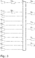
- the inventive method starting from an intensive care unit (19), as shown in FIG. 2 is sketched in the FIG. 3 shown.
- the bed recorders (2) associated with sound pickup (5, 6, 7) record sound sequences and forward them as electrical signals, for example, wired to the control unit (35).
- the electrical signals are conducted via suitable low-pass filters (21), so that the electrical signals of the sound pickups (5, 6, 7) can be fed to the control unit (35) in a low-pass filtered band-limited manner.
- the electrical sum signal - also wired, for example - only a preferred reference low-pass filter (23) supplied, which also the sum signal band-limited low-pass filtered before it is then also the evaluation unit (35) is supplied.
- the procedure is designed so that the sound sequences recorded by the sound sensors (5, 6, 7) of the individual bed positions (2) be registered such that z. B. the sound pickup (5) receives the alarm signal generated at its location immediately, and the other sound pickup (6, 7) receive a corresponding, but by the spatial distance but reduced sum signal.
- the signal sensor (5) will also record a distance-reduced sum signal from the alarm transmitter (s) of another location to which alarm devices of further diagnostic and therapeutic devices (1) are active, and the sound sensor responsible for this location - e.g. B. the sound pickup (6) - at the same time receives the resulting alarm signal directly in place. This applies to each other for each of the individual station sound pickups (5, 6, 7).
- the internal reference sound pickup (4) picks up the sound sequence as the sum signal of all simultaneously occurring alarm signals. All these Direct and mixed signals are fed to the signal analysis / decision preparation and output evaluation unit (35). Here, a separation between an indifferent or differentiated signal evaluation is performed. In the former, the recognition is made on the basis of specific characteristics common to the tones; in the second, the alarming devices are detected using previously created reference files (R 1 ).
- the electrical signal amplitudes of each of the individual tone sequences - external and internal - preferably compared by a fixed-point FFT and evaluated so that only those frequencies are further analyzed whose amplitudes in space are greater than the amplitudes the same frequency in front of the room; At the same time, however, these frequencies are also compared with acoustic reference patterns stored in the control unit (35) in order not to display a same alarm in the intensive care unit (19) outside the intensive care unit (19) from a neighboring station, since this would otherwise be misinterpreted correspond.
- the frequency resolution of the fixed-point FFT should preferably be at most + 9.375 Hz in the band-limited low-pass filter of the frequency 0 to 5000 Hz, with an amplitude drop of more than -3 dB and be detected at a respective distance of 18.75 Hz.
- control unit (35) may preferentially receive the signals from an alarm threshold controller (26) for device alarms, from a selective changeover switch (27) for a selective acoustic or full acoustic output, from a mechanical (mechanical) control, for example.
- Threshold controller (31) for device identification, from an acoustic changeover switch (32) to select an acoustic output mode, from an acoustic actuator (33) to control the acoustic volume of the output acoustic signals, and from a 1-bit input.
- Output switch (34) for switching on and off of the speech output supplied. All signals of this switch and controllers are used for manual adjustments and influencing desired processes.
- An alarming device can be correctly detected with a very high probability if the conditions of the above points are sufficiently satisfied.
- the signal patterns can - as soon as an alarm tone recognition, starts indifferent or differentiated - by each individual internal or external sound sensor (4, 5, 6, 7, 9, 10, 11, 12) detected in space amplitudes of the frequency relevant for this detection for the Duration of detection are stored in order to constantly adapt this stored audio signal pattern successively to the reference data to supplement the mean values of the signal pattern, expand and perfect.
- spoken bed space numbers as an acoustic output, which are created by a speech synthesizer, according to the prior art, and also the internal acoustic generator (15) and the external acoustic transmitters (16) are supplied.
- FIG. 4 typical relevant temporal waveforms for an alarm check for the diagnosis and therapy device to be determined (1) are shown.
- the device alarms of the diagnosis and therapy devices (1) usually consist of a frequency mixture; composed of the fundamental and several harmonics. Usually, in the prior art, this frequency mix is spectrally analyzed to then process it for decision making and use it for decisions.
- the alarm tones emitted by the medical diagnosis and therapy systems (1) are evaluated to determine whether their fundamental vibrations or one of the harmonics characterize the system particularly accurately.
- the frequency thus selected for the single system then provides the signal for the current amplitude (F).
- signals that fulfill this condition (s) are always compared with each other and stored as a reference file (R 1 ).
- This reference file (R 1 ) is generated for each diagnosis and therapy device (1) from the stored values and as a time course - abscissa the FIG. 4a - stored in the evaluation unit (35).
- a dynamic threshold (DS) which is adjusted in amplitude according to the respectively determined amplitude values, is used for further decision-making, for which a reference level (0) is defined.
- the amplitude (A) of the currently measured signal curve (F) minus the amplitude (A) of the frequency of the previously stored reference file (R 1 ) is the current amplitude difference ( ⁇ A) relative to a dynamic zero value ( ⁇ S ) - educated. This is in the FIGS. 4a and 4b shown. The difference is then positive if the amplitude (A) of the detected current waveform (F) is greater than the amplitude (A) determined for the reference file (R 1 ) and it is negative if the
- the reference file (R 1 ) and the currently determined sound event (F) are more similar to positive difference values of the actual amplitude difference ( ⁇ A) than to negative difference values - see FIG. 4b - And thus the positive difference value can be used to reduce the false alarm probability.
Landscapes
- Physics & Mathematics (AREA)
- General Physics & Mathematics (AREA)
- Measuring And Recording Apparatus For Diagnosis (AREA)
Claims (10)
- Procédé de surveillance d'appareils de diagnostic et de thérapie (1) comprenant des émetteurs d'alarme acoustique associés à au moins deux emplacements de lit dans une chambre de patients (3) d'un service médical de soins intensifs (19) pour commander un système de surveillance qui comprend les éléments suivants :- un capteur de sons (5, 6, 7) associé à chaque emplacement de lit et destiné à enregistrer des sons d'alarme émis par les émetteurs d'alarme acoustique,- au moins un capteur de sons de référence (4) destiné à enregistrer un son de chambre de référence à l'intérieur de la chambre de patient (3),- à chaque emplacement de lit, au moins une unité de sortie (13, 14, 16, 18) correspondante qui identifie l'emplacement de lit lorsqu'une alarme est déclenchée à cet emplacement,- une unité de commande (35) destinée à traiter les sons d'alarme enregistrés et le son de chambre de référence ainsi qu'à commander les unités de sortie (13, 14, 16, 18),caractérisé en ce que le procédé comprend au moins les étapes de procédé suivantes consistant à :- détecter et évaluer les sons d'alarme et le son de chambre de référence au moyen de l'unité de commande ;
élaborer des successions de sons de référence comprenant des successions de sons émetteurs d'alarme pour chacun des émetteurs d'alarme acoustique et mettre en mémoire les successions de sons de référence dans l'unité de commande ;
comparer entre eux les niveaux sonores respectifs des successions de sons identiques qui sont enregistrés par les capteurs de sons et le niveau sonore du son de chambre de référence ;
déterminer le capteur de sons qui a enregistré la succession de sons présentant le niveau sonore le plus élevé ;
comparer la succession de sons qui présente le niveau sonore le plus élevé aux successions de sons de référence des différents émetteurs d'alarme acoustique ; générer une valeur numérique en tant que mesure de la conformité entre(a) la succession de sons présentant le niveau sonore le plus élevé
et(b) la succession de sons de référence qui présente la conformité la plus élevée avec la succession de sons présentant le niveau sonore le plus élevé,- comparer la valeur numérique Z générée à des limites de plage d'alarme A, B préalablement définies à l'intérieur desquelles une alarme est émise,- commander l'unité de sortie associée à l'emplacement de lit (2) dont le capteur de sons (5, 6, 7) a enregistré la succession de sons présentant le niveau sonore le plus élevé. - Procédé selon la revendication 1, caractérisé en ce que l'unité de sortie est une lampe de signalisation d'emplacement de lit ou une lampe de signalisation externe, et en ce qu'un allumage d'une lampe de signalisation d'emplacement de lit (13) et/ou d'une lampe de signalisation externe (14) est réalisé sous la forme de clignotements présentant différentes fréquences de clignotement pour des alarmes à classifier en fonction des différences de gravité.
- Système de surveillance pour la mise en oeuvre du procédé selon la revendication 1 ou 2 pour des appareils de diagnostic et de thérapie (1) associés à des emplacements de lit (2) et comprenant des émetteurs d'alarme acoustique pour un service médical de soins intensifs (19) comprenant au moins deux emplacements de lit (2) dans une chambre de patient (3) pour la surveillance centrale de dispositifs médicaux :système dans lequel- au moins un capteur de sons (5, 6, 7) sert à enregistrer les sons d'alarme émis par les émetteurs d'alarme acoustique des appareils de diagnostic et de thérapie (1) associés à un emplacement de lit (2) et un capteur de sons de référence (4) destiné à enregistrer un son de chambre de référence à l'intérieur de la chambre de patient (3) est prévu,caractérisé en ce queun capteur de sons (5, 6, 7) est prévu pour chaque emplacement de lit (2),- une unité de sortie (13, 14, 16, 18) identifiant au moins un emplacement de lit (2) associé lorsqu'une alarme est déclenchée à cet emplacement,- une unité de commande (35) destinée à traiter des sons d'alarme enregistrés et le son de chambre de référence ainsi qu'à commander l'au moins une unité de sortie (13, 14, 16, 18) identifiant l'au moins un emplacement de lit (2) lorsqu'une alarme est déclenchée à cet emplacement.
- Système de surveillance pour un service médical de soins intensifs (19) selon la revendication 3, caractérisé en ce que le système de surveillance comprend pour chaque chambre de patient (3) au moins un capteur de sons de référence (4) destiné à enregistrer un son de chambre de référence à l'intérieur de cette chambre de patient (3) associée.
- Système de surveillance pour un service médical de soins intensifs (19) selon l'une des revendications 3 et 4, caractérisé en ce que l'unité de sortie (13, 14, 16, 18) identifiant une alarme est de préférence au moins un élément commandé par l'unité de commande (35), choisi dans la liste comprenant :- une lampe de signalisation d'emplacement de lit (13),- une lampe de signalisation externe (14),- un émetteur acoustique externe (16),- une optique d'affichage externe (18).
- Système de surveillance pour un service médical de soins intensifs (19) selon l'une des revendications 3 à 5, caractérisé en ce que le système de surveillance comprend des émetteurs acoustiques internes (15) et/ou au moins une optique d'affichage interne (17).
- Système de surveillance pour un service médical de soins intensifs (19) selon l'une des revendications 5 et 6, caractérisé en ce que les émetteurs acoustiques externes (16) et/ou les émetteurs acoustiques internes (15) sont conçus pour délivrer des numéros d'emplacement de lit vocaux en tant que sortie acoustique de l'alarme actuelle.
- Système de surveillance pour un service médical de soins intensifs (19) selon l'une des revendications 3 à 7, caractérisé en ce que le système de surveillance comprend des dispositifs d'appel du personnel, ces dispositifs d'appel du personnel étant reçus par les capteurs de sons (5, 6, 7) installés dans le service de soins intensifs (19) et affichés et/ou commandés en tant que signal évalué séparément dans l'unité d'évaluation (35).
- Système de surveillance pour un service médical de soins intensifs (19) selon l'une des revendications 3 à 8, caractérisé en ce que le système de surveillance comprend à chaque ouverture d'accès au service de soins intensifs (19) au moins un capteur de sons externe (9, 10, 11, 12).
- Système de surveillance pour un service médical de soins intensifs (19) selon l'une des revendications 3 à 9, caractérisé en ce qu'un fichier de données de référence permettant le traitement électronique est établi par l'unité de commande (35) à partir du son de chambre de référence enregistré au moyen du au moins un capteur de sons de référence (4).
Applications Claiming Priority (2)
| Application Number | Priority Date | Filing Date | Title |
|---|---|---|---|
| DE102011118389A DE102011118389A1 (de) | 2011-11-14 | 2011-11-14 | Überwachungssystem für medizinische Intensivstation |
| DE201210007891 DE102012007891A1 (de) | 2012-04-23 | 2012-04-23 | Verfahren zur Ansteuerung eines Überwachungssystems für medizinische Intensivstation |
Publications (2)
| Publication Number | Publication Date |
|---|---|
| EP2592604A1 EP2592604A1 (fr) | 2013-05-15 |
| EP2592604B1 true EP2592604B1 (fr) | 2017-06-14 |
Family
ID=47429534
Family Applications (1)
| Application Number | Title | Priority Date | Filing Date |
|---|---|---|---|
| EP12192260.3A Not-in-force EP2592604B1 (fr) | 2011-11-14 | 2012-11-12 | Système de surveillance et procédé de commande d'un système de surveillance pour un poste médical de soins intensifs |
Country Status (1)
| Country | Link |
|---|---|
| EP (1) | EP2592604B1 (fr) |
Families Citing this family (2)
| Publication number | Priority date | Publication date | Assignee | Title |
|---|---|---|---|---|
| EP4072658B1 (fr) * | 2019-12-11 | 2023-11-08 | Ged Gesellschaft für Elektronik und Design mbH | Dispositif pour renforcer le sens de l'équilibre |
| CN111314412A (zh) * | 2019-12-17 | 2020-06-19 | 西安交通大学医学院第二附属医院 | 一种多功能心血管内科监护装置 |
Family Cites Families (2)
| Publication number | Priority date | Publication date | Assignee | Title |
|---|---|---|---|---|
| AU8070482A (en) * | 1981-02-20 | 1982-08-26 | Rorke, W.F. | Body function monitor and alarm |
| FR2932916A1 (fr) | 2008-06-20 | 2009-12-25 | Buissiere Michel Marie Frederi | Systeme d'alerte medicale et procede correspondant |
-
2012
- 2012-11-12 EP EP12192260.3A patent/EP2592604B1/fr not_active Not-in-force
Non-Patent Citations (1)
| Title |
|---|
| None * |
Also Published As
| Publication number | Publication date |
|---|---|
| EP2592604A1 (fr) | 2013-05-15 |
Similar Documents
| Publication | Publication Date | Title |
|---|---|---|
| DE102007038392B4 (de) | Vorrichtung und Verfahren zur Vorhersage eines Kontrollverlustes über einen Muskel | |
| EP0205931B1 (fr) | Dispositif de mesure de fonctions vitales d'un sujet, en particulier d'un nourrisson | |
| DE3815633C2 (fr) | ||
| DE69312066T2 (de) | Medizinischer signalanalysator. | |
| DE102009044569A1 (de) | Steuerung eines Alarmzustands auf der Basis der Anwesenheit oder Abwesenheit einer Pflegekraft in einem Patientenraum | |
| EP0727962A1 (fr) | Procede et dispositif de detection automatique de bruits respiratoires anormaux | |
| DE1248225B (de) | Verfahren und Vorrichtung zum genauen Ermitteln der Herzschlagfrequenz | |
| EP3748536A1 (fr) | Système et procédé de détection automatique de situations dangereuses | |
| EP2592604B1 (fr) | Système de surveillance et procédé de commande d'un système de surveillance pour un poste médical de soins intensifs | |
| DE102012209612B4 (de) | Verfahren und Anordnung zur Überwachung der momentanen Mobilität von Personen in privaten oder öffentlichen Räumen | |
| DE112010005203T5 (de) | Blutdrucksystem zum Anzeigen des Namens einer Erkrankung | |
| EP2377460A1 (fr) | Système de reconnaissance précoce d'états mettant la vie de personnes en danger | |
| EP3765926B1 (fr) | Système de capteurs de bâtiment | |
| CH709806A1 (de) | Vorrichtung zur Führung von Sehbehinderten und Blinden. | |
| DE102012007891A1 (de) | Verfahren zur Ansteuerung eines Überwachungssystems für medizinische Intensivstation | |
| CH697402B1 (de) | Vorrichtung und Verfahren zur Erfassung und Verarbeitung von lebensbedrohenden Gesundheits-Gefahren bei älteren und behinderten Personen. | |
| DE102011118389A1 (de) | Überwachungssystem für medizinische Intensivstation | |
| DE19834257C2 (de) | Verfahren zur Überwachung eines Tieres, insbesondere eines Pferdes | |
| DE10114383B4 (de) | Blutdruckvorrichtung und Gerät zur extrakorporalen Blutbehandlung mit einer solchen Blutüberwachungsvorrichtung | |
| EP4270347A2 (fr) | Système de sécurité | |
| EP2196086A1 (fr) | Dispositif de surveillance de grands animaux | |
| DE1616005A1 (de) | Fernueberwachungsanlage | |
| EP0849716A2 (fr) | Procédé et dispositif pour surveiller des personnes à risque avec alarme automatique | |
| DE102016211049A1 (de) | Verfahren und Vorrichtung zum eine Vorrichtung und ein Verfahren zur Ausgabe wenigstens eines Alarmsignals | |
| LU502137B1 (de) | Meldevorrichtung für medizintechnische Geräte und Verfahren |
Legal Events
| Date | Code | Title | Description |
|---|---|---|---|
| PUAI | Public reference made under article 153(3) epc to a published international application that has entered the european phase |
Free format text: ORIGINAL CODE: 0009012 |
|
| AK | Designated contracting states |
Kind code of ref document: A1 Designated state(s): AL AT BE BG CH CY CZ DE DK EE ES FI FR GB GR HR HU IE IS IT LI LT LU LV MC MK MT NL NO PL PT RO RS SE SI SK SM TR |
|
| AX | Request for extension of the european patent |
Extension state: BA ME |
|
| 17P | Request for examination filed |
Effective date: 20131114 |
|
| RBV | Designated contracting states (corrected) |
Designated state(s): AL AT BE BG CH CY CZ DE DK EE ES FI FR GB GR HR HU IE IS IT LI LT LU LV MC MK MT NL NO PL PT RO RS SE SI SK SM TR |
|
| 17Q | First examination report despatched |
Effective date: 20161005 |
|
| STAA | Information on the status of an ep patent application or granted ep patent |
Free format text: STATUS: EXAMINATION IS IN PROGRESS |
|
| GRAP | Despatch of communication of intention to grant a patent |
Free format text: ORIGINAL CODE: EPIDOSNIGR1 |
|
| STAA | Information on the status of an ep patent application or granted ep patent |
Free format text: STATUS: GRANT OF PATENT IS INTENDED |
|
| INTG | Intention to grant announced |
Effective date: 20170317 |
|
| GRAS | Grant fee paid |
Free format text: ORIGINAL CODE: EPIDOSNIGR3 |
|
| GRAA | (expected) grant |
Free format text: ORIGINAL CODE: 0009210 |
|
| STAA | Information on the status of an ep patent application or granted ep patent |
Free format text: STATUS: THE PATENT HAS BEEN GRANTED |
|
| AK | Designated contracting states |
Kind code of ref document: B1 Designated state(s): AL AT BE BG CH CY CZ DE DK EE ES FI FR GB GR HR HU IE IS IT LI LT LU LV MC MK MT NL NO PL PT RO RS SE SI SK SM TR |
|
| REG | Reference to a national code |
Ref country code: GB Ref legal event code: FG4D Free format text: NOT ENGLISH |
|
| REG | Reference to a national code |
Ref country code: CH Ref legal event code: EP Ref country code: AT Ref legal event code: REF Ref document number: 901639 Country of ref document: AT Kind code of ref document: T Effective date: 20170615 |
|
| REG | Reference to a national code |
Ref country code: IE Ref legal event code: FG4D Free format text: LANGUAGE OF EP DOCUMENT: GERMAN |
|
| REG | Reference to a national code |
Ref country code: DE Ref legal event code: R096 Ref document number: 502012010532 Country of ref document: DE |
|
| RAP2 | Party data changed (patent owner data changed or rights of a patent transferred) |
Owner name: UNIVERSITAET ZU LUEBECK |
|
| REG | Reference to a national code |
Ref country code: CH Ref legal event code: NV Representative=s name: PATENTANWAELTE SCHAAD, BALASS, MENZL AND PARTN, CH Ref country code: CH Ref legal event code: PUE Owner name: UNIVERSITAET ZU LUEBECK, DE Free format text: FORMER OWNER: UNIVERSITAETSKLINIKUM SCHLESWIG-HOLSTEIN, DE |
|
| REG | Reference to a national code |
Ref country code: NL Ref legal event code: MP Effective date: 20170614 Ref country code: DE Ref legal event code: R081 Ref document number: 502012010532 Country of ref document: DE Owner name: UNIVERSITAET ZU LUEBECK, DE Free format text: FORMER OWNER: UNIVERSITAETSKLINIKUM SCHLESWIG-HOLSTEIN, 24105 KIEL, DE |
|
| REG | Reference to a national code |
Ref country code: LT Ref legal event code: MG4D |
|
| PG25 | Lapsed in a contracting state [announced via postgrant information from national office to epo] |
Ref country code: HR Free format text: LAPSE BECAUSE OF FAILURE TO SUBMIT A TRANSLATION OF THE DESCRIPTION OR TO PAY THE FEE WITHIN THE PRESCRIBED TIME-LIMIT Effective date: 20170614 Ref country code: ES Free format text: LAPSE BECAUSE OF FAILURE TO SUBMIT A TRANSLATION OF THE DESCRIPTION OR TO PAY THE FEE WITHIN THE PRESCRIBED TIME-LIMIT Effective date: 20170614 Ref country code: GR Free format text: LAPSE BECAUSE OF FAILURE TO SUBMIT A TRANSLATION OF THE DESCRIPTION OR TO PAY THE FEE WITHIN THE PRESCRIBED TIME-LIMIT Effective date: 20170915 Ref country code: NO Free format text: LAPSE BECAUSE OF FAILURE TO SUBMIT A TRANSLATION OF THE DESCRIPTION OR TO PAY THE FEE WITHIN THE PRESCRIBED TIME-LIMIT Effective date: 20170914 Ref country code: FI Free format text: LAPSE BECAUSE OF FAILURE TO SUBMIT A TRANSLATION OF THE DESCRIPTION OR TO PAY THE FEE WITHIN THE PRESCRIBED TIME-LIMIT Effective date: 20170614 Ref country code: LT Free format text: LAPSE BECAUSE OF FAILURE TO SUBMIT A TRANSLATION OF THE DESCRIPTION OR TO PAY THE FEE WITHIN THE PRESCRIBED TIME-LIMIT Effective date: 20170614 |
|
| REG | Reference to a national code |
Ref country code: GB Ref legal event code: 732E Free format text: REGISTERED BETWEEN 20171012 AND 20171018 |
|
| REG | Reference to a national code |
Ref country code: FR Ref legal event code: PLFP Year of fee payment: 6 |
|
| PG25 | Lapsed in a contracting state [announced via postgrant information from national office to epo] |
Ref country code: LV Free format text: LAPSE BECAUSE OF FAILURE TO SUBMIT A TRANSLATION OF THE DESCRIPTION OR TO PAY THE FEE WITHIN THE PRESCRIBED TIME-LIMIT Effective date: 20170614 Ref country code: BG Free format text: LAPSE BECAUSE OF FAILURE TO SUBMIT A TRANSLATION OF THE DESCRIPTION OR TO PAY THE FEE WITHIN THE PRESCRIBED TIME-LIMIT Effective date: 20170914 Ref country code: NL Free format text: LAPSE BECAUSE OF FAILURE TO SUBMIT A TRANSLATION OF THE DESCRIPTION OR TO PAY THE FEE WITHIN THE PRESCRIBED TIME-LIMIT Effective date: 20170614 Ref country code: RS Free format text: LAPSE BECAUSE OF FAILURE TO SUBMIT A TRANSLATION OF THE DESCRIPTION OR TO PAY THE FEE WITHIN THE PRESCRIBED TIME-LIMIT Effective date: 20170614 Ref country code: SE Free format text: LAPSE BECAUSE OF FAILURE TO SUBMIT A TRANSLATION OF THE DESCRIPTION OR TO PAY THE FEE WITHIN THE PRESCRIBED TIME-LIMIT Effective date: 20170614 |
|
| PG25 | Lapsed in a contracting state [announced via postgrant information from national office to epo] |
Ref country code: RO Free format text: LAPSE BECAUSE OF FAILURE TO SUBMIT A TRANSLATION OF THE DESCRIPTION OR TO PAY THE FEE WITHIN THE PRESCRIBED TIME-LIMIT Effective date: 20170614 Ref country code: CZ Free format text: LAPSE BECAUSE OF FAILURE TO SUBMIT A TRANSLATION OF THE DESCRIPTION OR TO PAY THE FEE WITHIN THE PRESCRIBED TIME-LIMIT Effective date: 20170614 Ref country code: EE Free format text: LAPSE BECAUSE OF FAILURE TO SUBMIT A TRANSLATION OF THE DESCRIPTION OR TO PAY THE FEE WITHIN THE PRESCRIBED TIME-LIMIT Effective date: 20170614 Ref country code: SK Free format text: LAPSE BECAUSE OF FAILURE TO SUBMIT A TRANSLATION OF THE DESCRIPTION OR TO PAY THE FEE WITHIN THE PRESCRIBED TIME-LIMIT Effective date: 20170614 |
|
| PG25 | Lapsed in a contracting state [announced via postgrant information from national office to epo] |
Ref country code: IS Free format text: LAPSE BECAUSE OF FAILURE TO SUBMIT A TRANSLATION OF THE DESCRIPTION OR TO PAY THE FEE WITHIN THE PRESCRIBED TIME-LIMIT Effective date: 20171014 Ref country code: IT Free format text: LAPSE BECAUSE OF FAILURE TO SUBMIT A TRANSLATION OF THE DESCRIPTION OR TO PAY THE FEE WITHIN THE PRESCRIBED TIME-LIMIT Effective date: 20170614 Ref country code: SM Free format text: LAPSE BECAUSE OF FAILURE TO SUBMIT A TRANSLATION OF THE DESCRIPTION OR TO PAY THE FEE WITHIN THE PRESCRIBED TIME-LIMIT Effective date: 20170614 Ref country code: PL Free format text: LAPSE BECAUSE OF FAILURE TO SUBMIT A TRANSLATION OF THE DESCRIPTION OR TO PAY THE FEE WITHIN THE PRESCRIBED TIME-LIMIT Effective date: 20170614 |
|
| REG | Reference to a national code |
Ref country code: DE Ref legal event code: R097 Ref document number: 502012010532 Country of ref document: DE |
|
| PLBE | No opposition filed within time limit |
Free format text: ORIGINAL CODE: 0009261 |
|
| STAA | Information on the status of an ep patent application or granted ep patent |
Free format text: STATUS: NO OPPOSITION FILED WITHIN TIME LIMIT |
|
| PG25 | Lapsed in a contracting state [announced via postgrant information from national office to epo] |
Ref country code: DK Free format text: LAPSE BECAUSE OF FAILURE TO SUBMIT A TRANSLATION OF THE DESCRIPTION OR TO PAY THE FEE WITHIN THE PRESCRIBED TIME-LIMIT Effective date: 20170614 |
|
| 26N | No opposition filed |
Effective date: 20180315 |
|
| PG25 | Lapsed in a contracting state [announced via postgrant information from national office to epo] |
Ref country code: MC Free format text: LAPSE BECAUSE OF FAILURE TO SUBMIT A TRANSLATION OF THE DESCRIPTION OR TO PAY THE FEE WITHIN THE PRESCRIBED TIME-LIMIT Effective date: 20170614 |
|
| PG25 | Lapsed in a contracting state [announced via postgrant information from national office to epo] |
Ref country code: LU Free format text: LAPSE BECAUSE OF NON-PAYMENT OF DUE FEES Effective date: 20171112 Ref country code: SI Free format text: LAPSE BECAUSE OF FAILURE TO SUBMIT A TRANSLATION OF THE DESCRIPTION OR TO PAY THE FEE WITHIN THE PRESCRIBED TIME-LIMIT Effective date: 20170614 |
|
| REG | Reference to a national code |
Ref country code: BE Ref legal event code: MM Effective date: 20171130 |
|
| REG | Reference to a national code |
Ref country code: IE Ref legal event code: MM4A |
|
| PG25 | Lapsed in a contracting state [announced via postgrant information from national office to epo] |
Ref country code: MT Free format text: LAPSE BECAUSE OF FAILURE TO SUBMIT A TRANSLATION OF THE DESCRIPTION OR TO PAY THE FEE WITHIN THE PRESCRIBED TIME-LIMIT Effective date: 20170614 |
|
| PG25 | Lapsed in a contracting state [announced via postgrant information from national office to epo] |
Ref country code: IE Free format text: LAPSE BECAUSE OF NON-PAYMENT OF DUE FEES Effective date: 20171112 |
|
| PG25 | Lapsed in a contracting state [announced via postgrant information from national office to epo] |
Ref country code: BE Free format text: LAPSE BECAUSE OF NON-PAYMENT OF DUE FEES Effective date: 20171130 |
|
| REG | Reference to a national code |
Ref country code: AT Ref legal event code: MM01 Ref document number: 901639 Country of ref document: AT Kind code of ref document: T Effective date: 20171112 |
|
| PG25 | Lapsed in a contracting state [announced via postgrant information from national office to epo] |
Ref country code: AT Free format text: LAPSE BECAUSE OF NON-PAYMENT OF DUE FEES Effective date: 20171112 |
|
| PG25 | Lapsed in a contracting state [announced via postgrant information from national office to epo] |
Ref country code: HU Free format text: LAPSE BECAUSE OF FAILURE TO SUBMIT A TRANSLATION OF THE DESCRIPTION OR TO PAY THE FEE WITHIN THE PRESCRIBED TIME-LIMIT; INVALID AB INITIO Effective date: 20121112 |
|
| PG25 | Lapsed in a contracting state [announced via postgrant information from national office to epo] |
Ref country code: CY Free format text: LAPSE BECAUSE OF NON-PAYMENT OF DUE FEES Effective date: 20170614 |
|
| PG25 | Lapsed in a contracting state [announced via postgrant information from national office to epo] |
Ref country code: MK Free format text: LAPSE BECAUSE OF FAILURE TO SUBMIT A TRANSLATION OF THE DESCRIPTION OR TO PAY THE FEE WITHIN THE PRESCRIBED TIME-LIMIT Effective date: 20170614 |
|
| PG25 | Lapsed in a contracting state [announced via postgrant information from national office to epo] |
Ref country code: TR Free format text: LAPSE BECAUSE OF FAILURE TO SUBMIT A TRANSLATION OF THE DESCRIPTION OR TO PAY THE FEE WITHIN THE PRESCRIBED TIME-LIMIT Effective date: 20170614 |
|
| PG25 | Lapsed in a contracting state [announced via postgrant information from national office to epo] |
Ref country code: PT Free format text: LAPSE BECAUSE OF FAILURE TO SUBMIT A TRANSLATION OF THE DESCRIPTION OR TO PAY THE FEE WITHIN THE PRESCRIBED TIME-LIMIT Effective date: 20170614 |
|
| PG25 | Lapsed in a contracting state [announced via postgrant information from national office to epo] |
Ref country code: AL Free format text: LAPSE BECAUSE OF FAILURE TO SUBMIT A TRANSLATION OF THE DESCRIPTION OR TO PAY THE FEE WITHIN THE PRESCRIBED TIME-LIMIT Effective date: 20170614 |
|
| PGFP | Annual fee paid to national office [announced via postgrant information from national office to epo] |
Ref country code: CH Payment date: 20201015 Year of fee payment: 9 Ref country code: DE Payment date: 20201013 Year of fee payment: 9 Ref country code: GB Payment date: 20201008 Year of fee payment: 9 Ref country code: FR Payment date: 20201014 Year of fee payment: 9 |
|
| REG | Reference to a national code |
Ref country code: DE Ref legal event code: R082 Ref document number: 502012010532 Country of ref document: DE Ref country code: DE Ref legal event code: R082 Ref document number: 502012010532 Country of ref document: DE Representative=s name: HEESCHEN, SVEN, DIPL.-PHYS., DE |
|
| REG | Reference to a national code |
Ref country code: DE Ref legal event code: R082 Ref document number: 502012010532 Country of ref document: DE Representative=s name: HEESCHEN, SVEN, DIPL.-PHYS., DE |
|
| REG | Reference to a national code |
Ref country code: DE Ref legal event code: R082 Ref document number: 502012010532 Country of ref document: DE Representative=s name: HEESCHEN, SVEN, DIPL.-PHYS., DE |
|
| REG | Reference to a national code |
Ref country code: DE Ref legal event code: R119 Ref document number: 502012010532 Country of ref document: DE |
|
| REG | Reference to a national code |
Ref country code: CH Ref legal event code: PL |
|
| GBPC | Gb: european patent ceased through non-payment of renewal fee |
Effective date: 20211112 |
|
| PG25 | Lapsed in a contracting state [announced via postgrant information from national office to epo] |
Ref country code: GB Free format text: LAPSE BECAUSE OF NON-PAYMENT OF DUE FEES Effective date: 20211112 Ref country code: DE Free format text: LAPSE BECAUSE OF NON-PAYMENT OF DUE FEES Effective date: 20220601 |
|
| PG25 | Lapsed in a contracting state [announced via postgrant information from national office to epo] |
Ref country code: FR Free format text: LAPSE BECAUSE OF NON-PAYMENT OF DUE FEES Effective date: 20211130 |
|
| PG25 | Lapsed in a contracting state [announced via postgrant information from national office to epo] |
Ref country code: LI Free format text: LAPSE BECAUSE OF NON-PAYMENT OF DUE FEES Effective date: 20220630 Ref country code: CH Free format text: LAPSE BECAUSE OF NON-PAYMENT OF DUE FEES Effective date: 20220630 |