EP2592748A2 - Bestimmung des Magnetflusses und der Temperatur eines Dauermagnets in einem Waschmaschinenmotor - Google Patents
Bestimmung des Magnetflusses und der Temperatur eines Dauermagnets in einem Waschmaschinenmotor Download PDFInfo
- Publication number
- EP2592748A2 EP2592748A2 EP12191284.4A EP12191284A EP2592748A2 EP 2592748 A2 EP2592748 A2 EP 2592748A2 EP 12191284 A EP12191284 A EP 12191284A EP 2592748 A2 EP2592748 A2 EP 2592748A2
- Authority
- EP
- European Patent Office
- Prior art keywords
- motor
- magnetic flux
- permanent magnets
- bemf
- waveform
- Prior art date
- Legal status (The legal status is an assumption and is not a legal conclusion. Google has not performed a legal analysis and makes no representation as to the accuracy of the status listed.)
- Withdrawn
Links
- 230000004907 flux Effects 0.000 title claims abstract description 64
- 238000005406 washing Methods 0.000 title claims abstract description 42
- 238000000034 method Methods 0.000 claims description 65
- 230000000284 resting effect Effects 0.000 claims description 9
- 230000008569 process Effects 0.000 description 12
- 230000008859 change Effects 0.000 description 3
- 230000001276 controlling effect Effects 0.000 description 3
- 238000010586 diagram Methods 0.000 description 3
- 230000001133 acceleration Effects 0.000 description 2
- 230000005540 biological transmission Effects 0.000 description 2
- 238000004140 cleaning Methods 0.000 description 2
- 230000005347 demagnetization Effects 0.000 description 2
- 230000006870 function Effects 0.000 description 2
- 238000003860 storage Methods 0.000 description 2
- 230000003213 activating effect Effects 0.000 description 1
- 230000003247 decreasing effect Effects 0.000 description 1
- 230000005611 electricity Effects 0.000 description 1
- 230000002427 irreversible effect Effects 0.000 description 1
- 238000004519 manufacturing process Methods 0.000 description 1
- 230000007246 mechanism Effects 0.000 description 1
- 230000004048 modification Effects 0.000 description 1
- 238000012986 modification Methods 0.000 description 1
- 229910001172 neodymium magnet Inorganic materials 0.000 description 1
- 230000003287 optical effect Effects 0.000 description 1
- 229910052761 rare earth metal Inorganic materials 0.000 description 1
- 150000002910 rare earth metals Chemical class 0.000 description 1
- 230000001105 regulatory effect Effects 0.000 description 1
- 230000004044 response Effects 0.000 description 1
- 230000001360 synchronised effect Effects 0.000 description 1
Images

Classifications
-
- H—ELECTRICITY
- H02—GENERATION; CONVERSION OR DISTRIBUTION OF ELECTRIC POWER
- H02P—CONTROL OR REGULATION OF ELECTRIC MOTORS, ELECTRIC GENERATORS OR DYNAMO-ELECTRIC CONVERTERS; CONTROLLING TRANSFORMERS, REACTORS OR CHOKE COILS
- H02P6/00—Arrangements for controlling synchronous motors or other dynamo-electric motors using electronic commutation dependent on the rotor position; Electronic commutators therefor
- H02P6/14—Electronic commutators
- H02P6/16—Circuit arrangements for detecting position
- H02P6/18—Circuit arrangements for detecting position without separate position detecting elements
- H02P6/182—Circuit arrangements for detecting position without separate position detecting elements using back-emf in windings
-
- D—TEXTILES; PAPER
- D06—TREATMENT OF TEXTILES OR THE LIKE; LAUNDERING; FLEXIBLE MATERIALS NOT OTHERWISE PROVIDED FOR
- D06F—LAUNDERING, DRYING, IRONING, PRESSING OR FOLDING TEXTILE ARTICLES
- D06F33/00—Control of operations performed in washing machines or washer-dryers
- D06F33/30—Control of washing machines characterised by the purpose or target of the control
-
- D—TEXTILES; PAPER
- D06—TREATMENT OF TEXTILES OR THE LIKE; LAUNDERING; FLEXIBLE MATERIALS NOT OTHERWISE PROVIDED FOR
- D06F—LAUNDERING, DRYING, IRONING, PRESSING OR FOLDING TEXTILE ARTICLES
- D06F34/00—Details of control systems for washing machines, washer-dryers or laundry dryers
- D06F34/08—Control circuits or arrangements thereof
-
- D—TEXTILES; PAPER
- D06—TREATMENT OF TEXTILES OR THE LIKE; LAUNDERING; FLEXIBLE MATERIALS NOT OTHERWISE PROVIDED FOR
- D06F—LAUNDERING, DRYING, IRONING, PRESSING OR FOLDING TEXTILE ARTICLES
- D06F34/00—Details of control systems for washing machines, washer-dryers or laundry dryers
- D06F34/10—Power supply arrangements, e.g. stand-by circuits
-
- H—ELECTRICITY
- H02—GENERATION; CONVERSION OR DISTRIBUTION OF ELECTRIC POWER
- H02P—CONTROL OR REGULATION OF ELECTRIC MOTORS, ELECTRIC GENERATORS OR DYNAMO-ELECTRIC CONVERTERS; CONTROLLING TRANSFORMERS, REACTORS OR CHOKE COILS
- H02P29/00—Arrangements for regulating or controlling electric motors, appropriate for both AC and DC motors
- H02P29/60—Controlling or determining the temperature of the motor or of the drive
- H02P29/67—Controlling or determining the motor temperature by back electromotive force [back-EMF] evaluation
-
- D—TEXTILES; PAPER
- D06—TREATMENT OF TEXTILES OR THE LIKE; LAUNDERING; FLEXIBLE MATERIALS NOT OTHERWISE PROVIDED FOR
- D06F—LAUNDERING, DRYING, IRONING, PRESSING OR FOLDING TEXTILE ARTICLES
- D06F37/00—Details specific to washing machines covered by groups D06F21/00 - D06F25/00
- D06F37/30—Driving arrangements
- D06F37/304—Arrangements or adaptations of electric motors
Definitions
- the present disclosure relates, generally, to drive systems for washing machines and, more particularly, to drive systems capable of determining a magnetic flux and a temperature of one or more permanent magnets in a washing machine motor.
- a washing machine is a domestic appliance for cleaning clothes, linens, and other laundry.
- a washing machine may include a tub and a drum that is positioned in the tub and is sized to receive laundry for cleaning.
- the washing machine may include an electric motor that causes the drum to rotate relative to the tub during a washing operation.
- the electric motor may be connected to the drum via a transmission system including, for example, cables and pulleys.
- the electric motor may also be connected to the drum via a drive shaft. Washing machines including the latter type of electric motor are often referred to as "direct drive" washing machines.
- Electric motors typically include a stator and a rotor configured to rotate relative to the stator.
- the stator may be fixed to the tub of the washing machine and may include a plurality of coils.
- the rotor may include one or more permanent magnets that interact with a magnetic field produced by one or more of the plurality of coils. During operation, the plurality of coils may be sequentially energized with electricity to cause the rotor to rotate.
- the rotor In a direct drive washing machine, the rotor may be torsionally secured to the drive shaft so that drive force may be transferred to the drum via the drive shaft.
- a washing machine may comprise a motor including a plurality of coils and one or more permanent magnets, an inverter configured to supply current to the plurality of coils and to measure a back electromotive force (BEMF) waveform from the plurality of coils, and an electronic control unit (ECU) configured to (i) integrate the BEMF waveform to generate an integrated BEMF waveform, (ii) determine a magnetic flux of the one or more permanent magnets using an amplitude of the integrated BEMF waveform, and (iii) control the current supplied by the inverter based at least in part upon the determined magnetic flux.
- BEMF back electromotive force
- the ECU may be further configured to control the inverter to measure the BEMF waveform while supplying no current to the plurality of coils.
- the ECU may be further configured to determine a temperature of the one or more permanent magnets by comparing the determined magnetic flux to a known magnetic flux corresponding to a known temperature.
- the ECU may be further configured to control the current supplied by the inverter based at least in part upon the determined temperature of the one or more permanent magnets.
- the ECU may be further configured to determine, using the determined magnetic flux, an optimized current for starting the motor from a resting state.
- a method may comprise measuring a back electromotive force (BEMF) waveform from a motor of a washing machine, integrating the BEMF waveform to generate an integrated BEMF waveform, determining a magnetic flux of one or more permanent magnets of the motor using an amplitude of the integrated BEMF waveform, and controlling a current supplied to the motor based at least in part upon the determined magnetic flux.
- BEMF back electromotive force
- measuring the BEMF waveform may comprise measuring the BEMF waveform using an inverter of the washing machine that supplies current to the motor. In other embodiments, measuring the BEMF waveform may comprise measuring the BEMF waveform while no current is being supplied to the motor. In such embodiments, measuring the BEMF waveform may comprise measuring the BEMF waveform while a drum of the washing machine decelerates.
- the method may further comprise determining a temperature of the one or more permanent magnets by comparing the determined magnetic flux to a known magnetic flux corresponding to a known temperature.
- controlling the current supplied to the motor may comprise controlling the current supplied to the motor based at least in part upon both the determined magnetic flux and the determined temperature of the one or more permanent magnets.
- the method may further comprise determining, using the determined magnetic flux, an optimized current for starting the motor from a resting state.
- one or more non-transitory, machine-readable media may comprise a plurality of instructions which, when executed, cause an electronic control unit (ECU) of a washing machine to receive a back electromotive force (BEMF) waveform measured from a motor of the washing machine, integrate the BEMF waveform to generate an integrated BEMF waveform, determine a magnetic flux of one or more permanent magnets of the motor using an amplitude of the integrated BEMF waveform, and control a current supplied to the motor based at least in part upon the determined magnetic flux.
- ECU electronice control unit
- BEMF back electromotive force
- the plurality of instructions may further cause the ECU to receive a BEMF waveform that was measured while no current was supplied to the motor. In other embodiments, the plurality of instructions may further cause the ECU to determine a temperature of the one or more permanent magnets by comparing the determined magnetic flux to a known magnetic flux corresponding to a known temperature. In such embodiments, the plurality of instructions may further cause the ECU to control the current supplied to the motor based at least in part upon the determined temperature of the one or more permanent magnets.
- the plurality of instructions may further cause the ECU to determine, using the determined magnetic flux, an optimized current for starting the motor from a resting state.
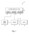
- FIG. 1 is a simplified block diagram of one illustrative embodiment of a drive system of a washing machine
- FIG. 2 is a simplified flowchart of a method of operating the drive system of FIG. 1 ;
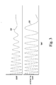
- FIG. 3 is a graph representing an illustrative back electromotive force (BEMF) waveform and its corresponding integrated BEMF waveform.
- BEMF back electromotive force
- Embodiments of the disclosed systems and methods may be implemented in hardware, firmware, software, or any combination thereof.
- Embodiments of the disclosed systems and methods implemented in a washing machine may include one or more point-to-point interconnects between components and/or one or more bus-based interconnects between components.
- Embodiments of the disclosed systems and methods may also be implemented as instructions stored on one or more non-transitory, machine-readable media, which may be read and executed by an electronic control unit.
- a non-transitory, machine-readable medium may include any mechanism for storing or transmitting information in a form readable by a machine (e.g., a processor).
- non-transitory, machine-readable media may include read only memory (ROM), random access memory (RAM), magnetic disk storage, optical storage, flash memory, and/or other types of memory devices.
- the drive system 10 illustratively includes an electric motor 12, an inverter 14, a power source 16, and an electronic control unit 18.
- the drive system 10 may include additional and/or different components than those shown in FIG. 1 and described herein.
- the drive system 10 of the washing machine generally controls the rotation of a drum relative to a tub to wash clothes, linens, and other laundry during a washing operation of the washing machine.
- the drive system 10 includes an electric motor 12, which may be connected to the drum of the washing machine indirectly via a transmission system or directly via a drive shaft, as described above.
- the motor 12 comprises a brushless, alternating current (AC) motor (also known as a permanent magnet synchronous motor). It will be appreciated that, in other embodiments, other types of electric motors may be used as the electric motor 12.
- the motor 12 includes a stator and a rotor configured to rotate relative to the stator (not shown). It is contemplated that both inner and outer rotor configurations may be used with the present disclosure.
- the motor 12 includes a plurality of coils (typically, positioned on the stator) and one or more permanent magnets (typically, positioned on the rotor). During operation, the plurality of coils may be sequentially supplied with current to generate magnetic fields that interact with the one or more permanent magnets and, thus, cause the rotor to rotate.
- the operation of the motor 12 may be enhanced by accurate determination of the magnetic flux and/or the temperature of the one or more permanent magnets of the motor 12 (these characteristics of the permanent magnets typically vary during operation of the motor 12). For instance, where the magnetic flux of the one or more permanent magnets is accurately known, the currents supplied to the plurality of coils of the motor 12 may be minimized or maximized within safe limits, depending on the desired performance. Lower motor currents may result in lower temperatures in the components of the motor 12 (e.g., the permanent magnets), which may improve the performance of and decrease the production cost of the motor 12. Furthermore, for certain types of permanent magnets that may be used in the motor 12 (e.g., rare-earth magnets, such as NdFeB magnets), accurately determining temperature can minimize the risk of irreversible demagnetization.
- rare-earth magnets such as NdFeB magnets
- the drive system 10 also includes an inverter 14 that draws electrical power from a power source 16 and supplies current to the plurality of coils of the motor 12.
- the power source 16 may be an AC mains power supply (e.g., 120 V, 60 Hz) to which the washing machine is connected.
- the power source 16 further comprises a power regulating circuit which also transforms AC mains power into direct current (DC) power and supplies this DC power to the electronic control unit 18.
- the inverter 14 is configured to sequentially supply current to the plurality of coils of the motor 12 over the electrical connections 20, 22, 24. In the illustrative embodiment of FIG.
- the motor 12 comprises three coils and, thus, includes three electrical connections 20, 22, 24 to the inverter 14 (i.e., one for each coil). It is contemplated that, in other embodiments, the motor 12 may comprise additional or fewer coils and have additional or fewer electrical connections to the inverter 14.
- the inverter 14 of the drive system 10 is further configured to measure a back electromotive force (BEMF) waveform from the motor 12 and supply the BEMF waveform (or information concerning the BEMF waveform) to the electronic control unit 18.
- BEMF back electromotive force
- the motor 12 When no currents are supplied to the motor 12 by the inverter 14 but the rotor of the motor 12 continues to rotate (due to momentum from previous operation of the motor 12), the motor 12 essentially operates as an electric generator. Under such conditions, the one or more permanent magnets of the motor 12 will induce voltages on the plurality of coils of the motor 12. These voltages are commonly referred to as "back electromotive force.”
- the BEMF produced by the motor 12 will be proportional to the time derivative of the magnetic flux of the one or more permanent magnets of the motor 12.
- the inverter 14 measures the BEMF waveform produced by the motor 12 while supplying no current to the plurality of coils (i.e., no current is supplied along any of the electrical connections 20, 22, 24). In other embodiments, however, the inverter 14 may be capable of measuring a BEMF waveform while supplying currents to one or more of the plurality of coils of the motor 12. Furthermore, although the inverter 14 is capable of measuring the BEMF waveform in the illustrative embodiment, it is also contemplated that one or more voltage sensors (separate from the inverter 14) may be positioned along one or more of the electrical connections 20, 22, 24 to measure a BEMF waveform.
- the drive system 10 also includes an electronic control unit (ECU) 18.
- the ECU 18 may be a dedicated controller for the drive system 10, or the ECU 18 may also control additional functions of the washing machine.
- the ECU 18 is, in essence, the master computer responsible for interpreting electrical signals sent by controls and sensors associated with the drive system 10 (and other components of the washing machine, in some embodiments) and for activating or energizing electronically-controlled components associated with the drive system 10 (and other components of the washing machine, in some embodiments).
- the ECU 18 is configured to control the inverter 14 to supply current to the plurality of coils of the motor 12, to receive various signals from the inverter 14 (e.g., a BEMF waveform, or information related thereto), and to determine when various operations of the drive system 10 should be performed, amongst many other things.
- the ECU 18 is operable to determine a magnetic flux of the one or more permanent magnets of the motor 12, a temperature of the one or more permanent magnets of the motor 12, and/or an optimized current for starting the motor 12 from a resting state, as necessary.
- the ECU 18 includes a number of electronic components commonly associated with electronic units utilized in the control of electromechanical systems.
- the ECU 18 may include, amongst other components customarily included in such devices, a processor such as a microprocessor 26 and a memory device 28.
- the memory device 28 may be embodied as one or more non-transitory, machine-readable media.
- the memory device 28 is provided to store, amongst other things, instructions in the form of, for example, a software routine (or routines) which, when executed by the microprocessor 26, allows the ECU 18 to control operation of the drive system 10.
- the ECU 18 also includes an analog interface circuit 30.
- the analog interface circuit 30 converts output signals (e.g., from the inverter 14) into signals which are suitable for presentation to an input of the microprocessor 26.
- the analog interface circuit 30 by use of an analog-to-digital (A/D) converter (not shown) or the like, converts analog signals into digital signals for use by the microprocessor 26.
- A/D converter may be embodied as a discrete device or number of devices, or may be integrated into the microprocessor 26.
- the ECU 18 may receive output signals from one or more current sensors, temperature sensors, rotor speed sensors, and/or rotor position sensors associated with the motor 12.
- the analog interface circuit 30 converts signals from the microprocessor 26 into output signals which are suitable for presentation to the electrically-controlled components associated with the drive system 10 (e.g., the inverter 14).
- the analog interface circuit 30 by use of a digital-to-analog (D/A) converter (not shown) or the like, converts the digital signals generated by the microprocessor 26 into analog signals for use by the electronically-controlled components associated with the drive system 10.
- D/A converter may be embodied as a discrete device or number of devices, or may be integrated into the microprocessor 26.
- the analog interface circuit 30 may be bypassed if the inverter 14 (or any other electronically-controlled component associated with the drive system 10) operates on a digital input signal, the analog interface circuit 30 may be bypassed.
- the ECU 18 may control and/or monitor operation of the motor 12 via the inverter 14.
- the ECU 18 executes a routine including, amongst other things, a control scheme in which the ECU 18 monitors one or more signals from the inverter 14 (e.g., a BEMF waveform) and any other sensors associated with the drive system 10 to control the current supplied by the inverter 14 to the plurality of coils of the motor 12.
- a control scheme in which the ECU 18 monitors one or more signals from the inverter 14 (e.g., a BEMF waveform) and any other sensors associated with the drive system 10 to control the current supplied by the inverter 14 to the plurality of coils of the motor 12.
- the ECU 18 may perform numerous calculations, either continuously or intermittently, including looking up values in preprogrammed tables, in order to execute algorithms to perform such functions as integrating a BEMF waveform received from the inverter 14, determining an amplitude of the integrated BEMF waveform, determining a magnetic flux of the one or more permanent magnets of the motor 12, determining a temperature of the one or more permanent magnets, determining an optimized current for starting the motor 12 from a resting state, etcetera.
- the operating process 100 may be executed by the ECU 18 (in conjunction with the inverter 14) to control the current supplied to the motor 12 based at least in part upon the magnetic flux of the one or more permanent magnets of the motor 12, determined using a BEMF waveform from the motor 12.
- the operating process 100 includes a number of process steps 102-116, as shown in FIG. 2 .
- Process steps 110, 112 may be optionally employed in the operating process 100 and are, therefore, indicated in phantom in FIG. 2 .
- the operating process 100 begins with process step 102, in which the ECU 18 instructs the inverter 14 to de-energize the motor 12.
- the inverter 14 Prior to process step 102, the inverter 14 will have energized the motor 12 by supplying current along the electrical connections 20, 22, 24.
- the inverter 14 will cease supplying current to the plurality of coils of the motor 12 in response to receiving an appropriate signal (or the absence of an appropriate signal) from the ECU 18. Due to prior momentum, however, the rotor of the motor 12 will continue to rotate in process step 102. Under these conditions (as described above), the motor 12 will generate a BEMF waveform that may be measured across a number of the electrical connections 20, 22, 24.
- the operating process 100 proceeds to process step 104, in which the inverter 14 measures the BEMF waveform that is generated by the motor 12.
- One illustrative BEMF waveform 200 that might be measured in process step 104 is graphically shown in FIG. 3 .
- the amplitude and frequency of the BEMF waveform 200 decrease over time as the rotor of the motor 12 slows down (the motor 12 being de-energized).
- the BEMF waveform 200 may be measured by one or more voltage sensors (separate from the inverter 14) positioned along one or more of the electrical connections 20, 22, 24. In any case, the inverter 14 or the one or more voltage sensors transmit the BEMF waveform 200 (or information concerning the BEMF waveform 200) to the ECU 18 in process step 104.
- process step 106 the ECU 18 integrates the BEMF waveform 200 to generate an integrated BEMF waveform 202.
- One illustrative integrated BEMF waveform 202 (corresponding to the BEMF waveform 200) that may be generated in process step 106 is also graphically shown in FIG. 3 .
- the ECU 18 may integrate the BEMF waveform 200 in real-time, as it is received from the inverter 14, or after the entire BEMF waveform 200 has been received.
- the peak-to-peak amplitude of the integrated BEMF waveform 202 generally remains constant, despite the decreasing amplitude and frequency of the BEMF waveform 200.
- the operating process 100 proceeds to process step 108, in which the ECU 18 determines a magnetic flux of the one or more permanent magnets of the motor 12 using the amplitude of the integrated BEMF waveform 202. This determination is possible because the peak-to-peak amplitude of the integrated BEMF waveform 202 is proportional to the magnetic flux of the one or more permanent magnets of the motor 12. Using the amplitude of the integrated BEMF waveform 202 as an input, the ECU 18 may determine the magnetic flux mathematically or via a look-up-table. After determining the magnetic flux of the one or more permanent magnets of the motor 12, the operating process 100 may proceed to process step 114. In some embodiments, however, the operating process 100 may first determine additional characteristics of the motor 12 and its one or more permanent magnets in process steps 110 and 112.
- the operating process 100 optionally proceeds to process step 110, in which the ECU 18 determines a temperature of the one or more permanent magnets of the motor 12. This determination is possible because the magnetic flux of the one or more permanent magnets is predictably related to the temperature of the one or more permanent magnets.
- the ECU 18 may determine the temperature of the one or more permanent magnets of the motor 12 by comparing the determined magnetic flux to a known magnetic flux corresponding to a known temperature. This known magnetic flux corresponding to a known temperature may be pre-programmed into the memory device 28 of the ECU 18 by designers of the motor 12. Additionally or alternatively, the known magnetic flux corresponding to a known temperature may have been determined by the ECU 18 at an earlier time and stored in the memory device 28 for later retrieval and comparison.
- ⁇ is the magnetic flux of the one or more permanent magnets of the motor 12 that was determined in process step 108
- ⁇ 0 is a known magnetic flux of the one or more permanent magnets corresponding to a known temperature T 0
- k is a constant for the motor 12.
- the ECU 18 may determine the temperature T of the one or more permanent magnets of the motor 12 either mathematically or via a look-up-table.
- process step 112 the ECU 18 determines an optimized current for starting the motor 12 from a resting state (i.e., a de-energized motor and/or a stationary rotor).
- This "optimized current” may be a minimum current required to start the motor 12 with minimum drum acceleration for a particular load or a maximum current that will preserve against demagnetization of the one or more permanent magnets of the motor 12 while giving maximum drum acceleration.
- the ECU 18 may determine the optimized current that should be supplied by the inverter 14. The optimized current will change with the magnetic flux of the one or more permanent magnets of the motor 12, which, in turn, will change with the temperature of the one or more permanent magnets.
- the optimized current for starting the motor 12 from a resting state will change over time, depending on the duty cycle of the washing machine. For example, at the beginning of a heavy duty cycle (e.g., several starts per hour), the motor 12 will be cooler, and a minimum starting current will be lower. As the one or more permanent magnets of the motor 12 increase in temperature (toward a thermal steady-state), the magnetic flux will be lower, and the minimum starting current will thus be higher. By calculating the minimum starting current for each start of motor 12, the drive system 10 may avoid supplying unneeded, excess current and causing the one or more permanent magnets to reach their peak temperature more quickly then necessary, resulting in greater efficiency for the motor 12.
- process step 114 the ECU 18 controls the current supplied to the motor 12 using the information determined in one or more of process steps 108, 110, 112. For instance, the ECU 18 may control the current supplied to the motor 12 based at least in part upon the determined magnetic flux and/or the determined temperature of the one or more permanent magnets (determined in process steps 108, 110, respectively). Additionally or alternatively, the ECU 18 may control the current supplied to the motor 12 using the minimum starting current determined in process step 112. In the illustrative embodiment, the ECU 18 controls the current supplied to the motor 12 by providing appropriate control signals to the inverter 14.
Landscapes
- Engineering & Computer Science (AREA)
- Textile Engineering (AREA)
- Power Engineering (AREA)
- Control Of Washing Machine And Dryer (AREA)
- Control Of Ac Motors In General (AREA)
- Control Of Motors That Do Not Use Commutators (AREA)
Applications Claiming Priority (1)
| Application Number | Priority Date | Filing Date | Title |
|---|---|---|---|
| US13/293,607 US9000699B2 (en) | 2011-11-10 | 2011-11-10 | Determination of magnetic flux and temperature of permanent magnets in washing machine motor |
Publications (2)
| Publication Number | Publication Date |
|---|---|
| EP2592748A2 true EP2592748A2 (de) | 2013-05-15 |
| EP2592748A3 EP2592748A3 (de) | 2014-05-14 |
Family
ID=47351416
Family Applications (1)
| Application Number | Title | Priority Date | Filing Date |
|---|---|---|---|
| EP12191284.4A Withdrawn EP2592748A3 (de) | 2011-11-10 | 2012-11-05 | Bestimmung des Magnetflusses und der Temperatur eines Dauermagnets in einem Waschmaschinenmotor |
Country Status (3)
| Country | Link |
|---|---|
| US (1) | US9000699B2 (de) |
| EP (1) | EP2592748A3 (de) |
| BR (1) | BR102012018537A2 (de) |
Cited By (1)
| Publication number | Priority date | Publication date | Assignee | Title |
|---|---|---|---|---|
| US11581835B1 (en) * | 2021-06-28 | 2023-02-14 | Amazon Technologies, Inc. | Sensor less magnet temperature estimation in permanent magnet machines |
Families Citing this family (3)
| Publication number | Priority date | Publication date | Assignee | Title |
|---|---|---|---|---|
| DE102017220685A1 (de) * | 2017-11-20 | 2019-05-23 | Robert Bosch Gmbh | Verfahren und Vorrichtung zum Betreiben einer elektrischen Maschine zur Abgabe eines vorgegebenen Drehmomentes und einer vorgegebenen Drehzahl |
| WO2021187865A1 (ko) * | 2020-03-16 | 2021-09-23 | 엘지전자 주식회사 | 의류처리장치 |
| WO2024038351A1 (en) * | 2022-08-19 | 2024-02-22 | Dyson Operations PTE. LTD. | A method of controlling a brushless permanent-magnet motor |
Family Cites Families (39)
| Publication number | Priority date | Publication date | Assignee | Title |
|---|---|---|---|---|
| US4654566A (en) | 1974-06-24 | 1987-03-31 | General Electric Company | Control system, method of operating an electronically commutated motor, and laundering apparatus |
| US4011489A (en) | 1974-11-20 | 1977-03-08 | General Electric Company | Apparatus for regulating magnetic flux in an AC motor |
| US4642537A (en) | 1983-12-13 | 1987-02-10 | General Electric Company | Laundering apparatus |
| US4642536A (en) * | 1984-04-19 | 1987-02-10 | General Electric Company | Control system for an electronically commutated motor, method of controlling such, method of controlling an electronically commutated motor and laundry apparatus |
| US4641066A (en) * | 1984-10-04 | 1987-02-03 | Nippondenso Co., Ltd. | Control apparatus for brushless motor |
| US4743815A (en) * | 1987-09-01 | 1988-05-10 | Emerson Electric Co. | Brushless permanent magnet motor system |
| DE3736303A1 (de) | 1987-10-27 | 1989-05-11 | Heidelberger Druckmasch Ag | Verfahren und vorrichtung zur messung der temperatur eines buerstenlosen gleichstrommotors |
| US5134349A (en) | 1991-05-28 | 1992-07-28 | Kruse David L | Two-phase brushless dc motor controller |
| KR100302103B1 (ko) | 1992-07-09 | 2001-10-22 | 구사마 사부로 | 무브러시모우터 |
| US5473240A (en) | 1993-12-30 | 1995-12-05 | Whirlpool Corporation | Motor control using third harmonic stator voltage signal |
| US5345156A (en) | 1993-12-30 | 1994-09-06 | Whirlpool Corporation | Control for high speed operation of brushless permanent magnet motor |
| US5422570A (en) * | 1993-12-30 | 1995-06-06 | Whirlpool Corporation | Speed sensing for the third harmonic stator voltage signal |
| US5635810A (en) * | 1995-09-20 | 1997-06-03 | Analog Devices, Inc. | Control system for a permanent magnet synchronous motor |
| US5739664A (en) | 1996-02-05 | 1998-04-14 | Ford Global Technologies, Inc. | Induction motor drive controller |
| US5796194A (en) | 1996-07-15 | 1998-08-18 | General Electric Company | Quadrature axis winding for sensorless rotor angular position control of single phase permanent magnet motor |
| US5920162A (en) * | 1996-08-05 | 1999-07-06 | Sundstrand Corporation | Position control using variable exciter feed through |
| US6462495B1 (en) | 2000-04-25 | 2002-10-08 | Infineon Technologies Ag | Controlling a brushless DC motor |
| US7066034B2 (en) * | 2001-11-12 | 2006-06-27 | International Rectifier Corporation | Start-up method and system for permanent magnet synchronous motor drive |
| US6901212B2 (en) | 2002-06-13 | 2005-05-31 | Halliburton Energy Services, Inc. | Digital adaptive sensorless commutational drive controller for a brushless DC motor |
| GB0221117D0 (en) | 2002-09-12 | 2002-10-23 | Black & Decker Inc | Control of electrical machines |
| US7157878B2 (en) | 2002-11-19 | 2007-01-02 | Delphi Technologies, Inc. | Transient compensation voltage estimation for feedforward sinusoidal brushless motor control |
| JP2004229462A (ja) * | 2003-01-27 | 2004-08-12 | Rohm Co Ltd | 電動機の制御装置 |
| US6903525B2 (en) | 2003-08-05 | 2005-06-07 | Kendro Laboratory Products, Lp | Motor temperature sensor system and method to determine motor performance |
| US7262536B2 (en) | 2003-08-11 | 2007-08-28 | General Motors Corporation | Gearless wheel motor drive system |
| US6841969B1 (en) | 2003-09-24 | 2005-01-11 | General Motors Corporation | Flux observer in a sensorless controller for permanent magnet motors |
| NZ530370A (en) | 2003-12-22 | 2005-06-24 | Fisher & Paykel Appliances Ltd | Single winding BEMF sensing brushless DC motor |
| JP2008505596A (ja) | 2004-07-01 | 2008-02-21 | インターナショナル レクティファイアー コーポレイション | 永久磁石同期電動機駆動の起動方法およびシステム |
| CA2512374A1 (en) | 2004-08-23 | 2006-02-23 | Agile Systems Inc. | System and method for sensor less magnetic field control of a motor |
| US7592761B2 (en) | 2005-09-29 | 2009-09-22 | Agile Systems Inc. | System and method for starting and operating a motor |
| ES2329928T3 (es) | 2006-03-17 | 2009-12-02 | Electrolux Home Products Corporation N.V. | Maquina lavadora de ropa con dispositivo medidor del par motor. |
| US7893643B2 (en) * | 2007-01-26 | 2011-02-22 | Stmicroelectronics, Inc. | Pair pole asymmetry compensation in back electromotive force zero cross detection |
| US8340848B2 (en) | 2007-11-29 | 2012-12-25 | GM Global Technology Operations LLC | Method and system for sensorless control of an electric motor |
| US20100060217A1 (en) | 2008-09-10 | 2010-03-11 | Aisan Kogyo Kabushiki Kaisha | Brushless motor starting method and control device |
| US8248039B2 (en) | 2009-06-30 | 2012-08-21 | Vestas Wind Systems A/S | Control system for an electrical generator and method for controlling an electrical generator |
| US8319460B2 (en) | 2009-10-27 | 2012-11-27 | GM Global Technology Operations LLC | Method and system for initiating operation of an electric motor |
| US8421255B2 (en) | 2009-10-28 | 2013-04-16 | General Electric Company | System and method for determining the temperature of a permanent magnet in a machine |
| US8519648B2 (en) * | 2011-07-22 | 2013-08-27 | GM Global Technology Operations LLC | Temperature compensation for improved field weakening accuracy |
| TWI439041B (zh) * | 2011-12-19 | 2014-05-21 | 財團法人工業技術研究院 | 永磁同步馬達驅動方法與裝置 |
| US8836260B2 (en) * | 2012-11-07 | 2014-09-16 | Remy Technologies, L.L.C. | Method and apparatus for reducing torque variation in motor drive systems |
-
2011
- 2011-11-10 US US13/293,607 patent/US9000699B2/en not_active Expired - Fee Related
-
2012
- 2012-07-26 BR BRBR102012018537-7A patent/BR102012018537A2/pt not_active IP Right Cessation
- 2012-11-05 EP EP12191284.4A patent/EP2592748A3/de not_active Withdrawn
Non-Patent Citations (1)
| Title |
|---|
| None |
Cited By (1)
| Publication number | Priority date | Publication date | Assignee | Title |
|---|---|---|---|---|
| US11581835B1 (en) * | 2021-06-28 | 2023-02-14 | Amazon Technologies, Inc. | Sensor less magnet temperature estimation in permanent magnet machines |
Also Published As
| Publication number | Publication date |
|---|---|
| BR102012018537A2 (pt) | 2013-10-01 |
| US9000699B2 (en) | 2015-04-07 |
| US20130119905A1 (en) | 2013-05-16 |
| EP2592748A3 (de) | 2014-05-14 |
Similar Documents
| Publication | Publication Date | Title |
|---|---|---|
| EP1997947A2 (de) | Waschmaschinenvorrichtung und Verfahren | |
| KR100348626B1 (ko) | 세탁기의 포량감지장치 | |
| US20110260671A1 (en) | Apparatus for selecting speed of electrically commutated motor for use in hvac system | |
| EP2410653B1 (de) | Vorrichtung zur Steuerung eines Synchronomotors mit einem Dauermagnetläufer und Regelungsverfahren für einen Permanentmagnet-Synchronmotor | |
| US6859001B2 (en) | Torque ripple and noise reduction by avoiding mechanical resonance for a brushless DC machine | |
| GB2549740A (en) | A method for controlling an electric motor | |
| KR20090053019A (ko) | 모터, 세탁기 모터의 제어장치 및 세탁기 모터의 제어방법 | |
| CN101512893A (zh) | 同步电机的控制 | |
| US9000699B2 (en) | Determination of magnetic flux and temperature of permanent magnets in washing machine motor | |
| US9979339B2 (en) | Synchronous electric power distribution startup system | |
| US9577552B2 (en) | Systems and methods for braking an electric motor | |
| US8952648B2 (en) | Washing machine with improved braking method | |
| US8390229B2 (en) | Washing machine with improved method of braking to a non-zero speed | |
| CN108983090B (zh) | 一种电机霍尔零点调节装置及其调节方法 | |
| US9602027B2 (en) | Systems, methods, and assemblies for detecting stoppage of electric motors | |
| RU2543998C1 (ru) | Схема управления синхронным двигателем с постоянными магнитами | |
| US20150349685A1 (en) | System and method for starting an electric motor | |
| EP3133732B1 (de) | Stromwandlervorrichtung und stromumwandlungsverfahren | |
| US8823301B2 (en) | Method and device for detecting rotor position in a permanent magnet synchronous motor-driven washing machine | |
| US9748878B1 (en) | Adaptive brake timing for a brushless motor | |
| GB2561094A (en) | A Method For Controlling An Electric Motor | |
| KR20090081051A (ko) | 모터, 모터의 제어장치, 모터의 제어방법, 및 세탁기 | |
| CN118998942A (zh) | 判断空调风机适配的方法、电子设备、空调器及存储介质 | |
| KR20160071498A (ko) | 저소음을 위한 스위치드 릴럭턴스 모터의 구동 제어 장치 및 구동 제어 방법 | |
| KR20220084574A (ko) | 모터 제어 장치 및 모터 제어 방법 |
Legal Events
| Date | Code | Title | Description |
|---|---|---|---|
| PUAI | Public reference made under article 153(3) epc to a published international application that has entered the european phase |
Free format text: ORIGINAL CODE: 0009012 |
|
| AK | Designated contracting states |
Kind code of ref document: A2 Designated state(s): AL AT BE BG CH CY CZ DE DK EE ES FI FR GB GR HR HU IE IS IT LI LT LU LV MC MK MT NL NO PL PT RO RS SE SI SK SM TR |
|
| AX | Request for extension of the european patent |
Extension state: BA ME |
|
| PUAL | Search report despatched |
Free format text: ORIGINAL CODE: 0009013 |
|
| AK | Designated contracting states |
Kind code of ref document: A3 Designated state(s): AL AT BE BG CH CY CZ DE DK EE ES FI FR GB GR HR HU IE IS IT LI LT LU LV MC MK MT NL NO PL PT RO RS SE SI SK SM TR |
|
| AX | Request for extension of the european patent |
Extension state: BA ME |
|
| RIC1 | Information provided on ipc code assigned before grant |
Ipc: H02P 6/18 20060101AFI20140408BHEP |
|
| 17P | Request for examination filed |
Effective date: 20141105 |
|
| RBV | Designated contracting states (corrected) |
Designated state(s): AL AT BE BG CH CY CZ DE DK EE ES FI FR GB GR HR HU IE IS IT LI LT LU LV MC MK MT NL NO PL PT RO RS SE SI SK SM TR |
|
| STAA | Information on the status of an ep patent application or granted ep patent |
Free format text: STATUS: EXAMINATION IS IN PROGRESS |
|
| 17Q | First examination report despatched |
Effective date: 20161212 |
|
| GRAP | Despatch of communication of intention to grant a patent |
Free format text: ORIGINAL CODE: EPIDOSNIGR1 |
|
| STAA | Information on the status of an ep patent application or granted ep patent |
Free format text: STATUS: GRANT OF PATENT IS INTENDED |
|
| INTG | Intention to grant announced |
Effective date: 20171026 |
|
| STAA | Information on the status of an ep patent application or granted ep patent |
Free format text: STATUS: THE APPLICATION IS DEEMED TO BE WITHDRAWN |
|
| 18D | Application deemed to be withdrawn |
Effective date: 20180306 |