EP2593683B1 - Selbstzentrierende schraube - Google Patents
Selbstzentrierende schraube Download PDFInfo
- Publication number
- EP2593683B1 EP2593683B1 EP11733828.5A EP11733828A EP2593683B1 EP 2593683 B1 EP2593683 B1 EP 2593683B1 EP 11733828 A EP11733828 A EP 11733828A EP 2593683 B1 EP2593683 B1 EP 2593683B1
- Authority
- EP
- European Patent Office
- Prior art keywords
- thread
- screw
- core
- screwing
- screw according
- Prior art date
- Legal status (The legal status is an assumption and is not a legal conclusion. Google has not performed a legal analysis and makes no representation as to the accuracy of the status listed.)
- Active
Links
Images


Classifications
-
- F—MECHANICAL ENGINEERING; LIGHTING; HEATING; WEAPONS; BLASTING
- F16—ENGINEERING ELEMENTS AND UNITS; GENERAL MEASURES FOR PRODUCING AND MAINTAINING EFFECTIVE FUNCTIONING OF MACHINES OR INSTALLATIONS; THERMAL INSULATION IN GENERAL
- F16B—DEVICES FOR FASTENING OR SECURING CONSTRUCTIONAL ELEMENTS OR MACHINE PARTS TOGETHER, e.g. NAILS, BOLTS, CIRCLIPS, CLAMPS, CLIPS OR WEDGES; JOINTS OR JOINTING
- F16B25/00—Screws that cut thread in the body into which they are screwed, e.g. wood screws
-
- F—MECHANICAL ENGINEERING; LIGHTING; HEATING; WEAPONS; BLASTING
- F16—ENGINEERING ELEMENTS AND UNITS; GENERAL MEASURES FOR PRODUCING AND MAINTAINING EFFECTIVE FUNCTIONING OF MACHINES OR INSTALLATIONS; THERMAL INSULATION IN GENERAL
- F16B—DEVICES FOR FASTENING OR SECURING CONSTRUCTIONAL ELEMENTS OR MACHINE PARTS TOGETHER, e.g. NAILS, BOLTS, CIRCLIPS, CLAMPS, CLIPS OR WEDGES; JOINTS OR JOINTING
- F16B25/00—Screws that cut thread in the body into which they are screwed, e.g. wood screws
- F16B25/001—Screws that cut thread in the body into which they are screwed, e.g. wood screws characterised by the material of the body into which the screw is screwed
- F16B25/0026—Screws that cut thread in the body into which they are screwed, e.g. wood screws characterised by the material of the body into which the screw is screwed the material being a hard non-organic material, e.g. stone, concrete or drywall
-
- F—MECHANICAL ENGINEERING; LIGHTING; HEATING; WEAPONS; BLASTING
- F16—ENGINEERING ELEMENTS AND UNITS; GENERAL MEASURES FOR PRODUCING AND MAINTAINING EFFECTIVE FUNCTIONING OF MACHINES OR INSTALLATIONS; THERMAL INSULATION IN GENERAL
- F16B—DEVICES FOR FASTENING OR SECURING CONSTRUCTIONAL ELEMENTS OR MACHINE PARTS TOGETHER, e.g. NAILS, BOLTS, CIRCLIPS, CLAMPS, CLIPS OR WEDGES; JOINTS OR JOINTING
- F16B25/00—Screws that cut thread in the body into which they are screwed, e.g. wood screws
- F16B25/0036—Screws that cut thread in the body into which they are screwed, e.g. wood screws characterised by geometric details of the screw
- F16B25/0042—Screws that cut thread in the body into which they are screwed, e.g. wood screws characterised by geometric details of the screw characterised by the geometry of the thread, the thread being a ridge wrapped around the shaft of the screw
- F16B25/0052—Screws that cut thread in the body into which they are screwed, e.g. wood screws characterised by geometric details of the screw characterised by the geometry of the thread, the thread being a ridge wrapped around the shaft of the screw the ridge having indentations, notches or the like in order to improve the cutting behaviour
-
- F—MECHANICAL ENGINEERING; LIGHTING; HEATING; WEAPONS; BLASTING
- F16—ENGINEERING ELEMENTS AND UNITS; GENERAL MEASURES FOR PRODUCING AND MAINTAINING EFFECTIVE FUNCTIONING OF MACHINES OR INSTALLATIONS; THERMAL INSULATION IN GENERAL
- F16B—DEVICES FOR FASTENING OR SECURING CONSTRUCTIONAL ELEMENTS OR MACHINE PARTS TOGETHER, e.g. NAILS, BOLTS, CIRCLIPS, CLAMPS, CLIPS OR WEDGES; JOINTS OR JOINTING
- F16B25/00—Screws that cut thread in the body into which they are screwed, e.g. wood screws
- F16B25/0036—Screws that cut thread in the body into which they are screwed, e.g. wood screws characterised by geometric details of the screw
- F16B25/0042—Screws that cut thread in the body into which they are screwed, e.g. wood screws characterised by geometric details of the screw characterised by the geometry of the thread, the thread being a ridge wrapped around the shaft of the screw
- F16B25/0057—Screws that cut thread in the body into which they are screwed, e.g. wood screws characterised by geometric details of the screw characterised by the geometry of the thread, the thread being a ridge wrapped around the shaft of the screw the screw having distinct axial zones, e.g. multiple axial thread sections with different pitch or thread cross-sections
-
- F—MECHANICAL ENGINEERING; LIGHTING; HEATING; WEAPONS; BLASTING
- F16—ENGINEERING ELEMENTS AND UNITS; GENERAL MEASURES FOR PRODUCING AND MAINTAINING EFFECTIVE FUNCTIONING OF MACHINES OR INSTALLATIONS; THERMAL INSULATION IN GENERAL
- F16B—DEVICES FOR FASTENING OR SECURING CONSTRUCTIONAL ELEMENTS OR MACHINE PARTS TOGETHER, e.g. NAILS, BOLTS, CIRCLIPS, CLAMPS, CLIPS OR WEDGES; JOINTS OR JOINTING
- F16B25/00—Screws that cut thread in the body into which they are screwed, e.g. wood screws
- F16B25/0036—Screws that cut thread in the body into which they are screwed, e.g. wood screws characterised by geometric details of the screw
- F16B25/0042—Screws that cut thread in the body into which they are screwed, e.g. wood screws characterised by geometric details of the screw characterised by the geometry of the thread, the thread being a ridge wrapped around the shaft of the screw
- F16B25/0068—Screws that cut thread in the body into which they are screwed, e.g. wood screws characterised by geometric details of the screw characterised by the geometry of the thread, the thread being a ridge wrapped around the shaft of the screw with multiple-threads, e.g. a double thread screws
-
- F—MECHANICAL ENGINEERING; LIGHTING; HEATING; WEAPONS; BLASTING
- F16—ENGINEERING ELEMENTS AND UNITS; GENERAL MEASURES FOR PRODUCING AND MAINTAINING EFFECTIVE FUNCTIONING OF MACHINES OR INSTALLATIONS; THERMAL INSULATION IN GENERAL
- F16B—DEVICES FOR FASTENING OR SECURING CONSTRUCTIONAL ELEMENTS OR MACHINE PARTS TOGETHER, e.g. NAILS, BOLTS, CIRCLIPS, CLAMPS, CLIPS OR WEDGES; JOINTS OR JOINTING
- F16B25/00—Screws that cut thread in the body into which they are screwed, e.g. wood screws
- F16B25/0036—Screws that cut thread in the body into which they are screwed, e.g. wood screws characterised by geometric details of the screw
- F16B25/0094—Screws that cut thread in the body into which they are screwed, e.g. wood screws characterised by geometric details of the screw the screw being assembled or manufactured from several components, e.g. a tip out of a first material welded to shaft of a second material
Definitions
- the invention relates to a self-centering screw for screwing into a borehole in a hard material, in particular concrete.
- the DE 299 17 000 U1 discloses a thread-forming screw for direct screwing into a bore which is incorporated in concrete, masonry or the like.
- a screw comprises a cylindrical core, an external thread formed integrally with the core, and a torque transmitting means disposed on the core. Furthermore, supporting elements for supporting the screw in the borehole during screwing are provided on the core.
- Fasteners for a hard material are known, for example in the form of concrete screws through public prior use.
- Such screws have a cylindrical core with a core diameter and an insertion end, whose diameter is reduced compared to the core diameter.
- an external thread of the screw is applied to an inner wall of the borehole in a region of a thread start.
- the screw When the screw is turned in a screwing-in direction, the screw may tilt on contact of the external thread with the inner wall of the borehole about a central longitudinal axis of the screw. As a result, the thread of the screw can not be screwed into the borehole. The screw does not hold.
- the invention has for its object to further develop a screw for screwing into a borehole in a hard material, in particular concrete, so that the screwing is improved.
- the object is solved by the features of claim 1.
- the gist of the invention is that the screw has at least one support member for supporting the screw in the wellbore during screwing. This prevents that when screwing the screw tilts this about the central longitudinal axis.
- the at least one support element thus acts as a centering aid.
- the screw according to the invention is self-centering during the screwing operation.
- the screw according to the invention comprises a cylindrical core with an insertion end, an outer end opposite thereto, a core diameter, a screwing-in direction and a central longitudinal axis parallel thereto. Furthermore, an integrally formed with the core, along a threaded portion extending outer thread for screwing the same is provided in the material.
- the external thread has a threaded diameter, a threaded start at the insertion end, and at least one cutting element for cutting the external thread into the material.
- a torque transmission means for transmitting a screw-in torque from a screw-in tool to the core of the screw is arranged on the core.
- the at least one support element is arranged in the region of the thread start and arranged with respect to the central longitudinal axis of the at least one cutting element diametrically opposite to the core. This ensures that upon engagement of the cutting element in the hard material, the screw is supported on a side opposite the cutting element side in the well and thus safely guided.
- the at least one support element may be designed as a protruding from the core survey.
- the at least one support element may be designed as a welded-on cutting pin.
- the particularly hard running cutting pins can be anchored in holes provided in the screw.
- the at least one support element may be arranged according to a preferred embodiment along a helical line on the core, wherein the helix comprises at most one thread, in particular at most 80% of a thread and in particular at most 50% of a thread.
- the helix and the outer thread have identical thread pitches, so that as a result of screwing the central longitudinal axis of the screw is centered with increasing depth of engagement in the borehole.
- the screw may have on a cutting element a cutting element diameter which is larger than the thread diameter.
- the screw on the at least one support element may have a support element diameter which is smaller than the thread diameter. Characterized in that the cutting element diameter is greater than the thread diameter the cutting of the screw is facilitated in the hard material.
- the fact that the support element diameter is smaller than the thread diameter ensures that a concrete web remaining in the borehole between the support thread is not damaged and thus the load capacity of the screw screwed into the borehole is improved.
- the screw 1 is suitable for screwing into a borehole in a hard material, in particular, concrete with a concrete strength of at least C30 or other hard natural stones, such as sandstone or granite.
- the screw 1 can also be used for softer materials.
- the screw 1 has a substantially cylindrical core 2 with an insertion end 3, an outer end 4 opposite thereto, a screw-in direction 5, an outer circumference 6 and a central longitudinal axis 7 running parallel to the screw-in direction 5.
- an external thread 8 is formed, which extends from the insertion end 3 counter to the direction 5 along a threaded portion of the length A G.
- the external thread 8 is self-tapping along a cutting section of the length A S extending from the insertion end 3 opposite to the screwing-in direction 5 and has at least one cutting element on the external thread 8 for this purpose.
- the core 2 has a core diameter D K and the external thread 8 a thread diameter D G , wherein the thread diameter D G is greater than the core diameter D K.
- the cutting section A S is followed by a normal thread section of length AN, in which no cutting elements 9 are provided on the external thread 8.
- a S + AN A G.
- the threaded portion A G is followed by a circular-cylindrical cylinder portion of length A Z , which has a substantially smooth surface.
- the cylinder section A Z is adjoined by a collar section A K which extends to the outer end 4 and which is described in more detail below.
- the core 2 tapers approximately along the height H G of a thread in the region of the insertion end 3 in the form of a conical section.
- the total length L of the screw 1 is composed of A G + A Z + A K.
- a blind hole 10 which is open concentrically to the central longitudinal axis 7 opposite to the screwing-in direction 5 is arranged.
- the blind hole 10 has an internal thread 11.
- the inner thread 11 is preferably a normal one Metal thread.
- the inner thread 11 extends only over a part, for example 3 ⁇ 4 of the depth of the blind hole 10.
- the inner thread 11 is used for example for a fastening element which can be screwed to the screw 1.
- the screw 1 it is possible to use the screw 1 as a fixing anchor in a hard material such as concrete.
- the wall of the blind hole 10 in the form of an inner hexagon 12, wherein the maximum inner diameter of the inner hexagon 12 is smaller than the inner diameter of the inner thread 11.
- the core 2 has a collar 13 projecting radially relative to the core 2 and formed integrally with the core 2.
- the collar 13 has opposite to the direction 5 on a flat, perpendicular to the axis 7 extending end face 14.
- the axial thickness of the collar 13 is reduced with increasing radial distance, ie, the collar 13 is bounded by the end face 14 and an obliquely extending to this flank surface 15, wherein both intersect at an acute angle. It is basically possible to make the cross section of the collar 13 different, for example disc-shaped.
- a hexagonal head or another means for transmitting torque can be attached for screwing in the screw 1.
- the collar 13 has an outer diameter D KR .
- the core 2 has an outer diameter D KE .
- the external thread 8 has a threaded end 16, which is arranged at the insertion end 3. Furthermore, on the core 2 a plurality of support elements 17 for supporting the screw 1 in a borehole during a Screwing provided.
- the support elements 17 are arranged in the region of the thread start 16 and arranged with respect to the central longitudinal axis 7 diametrically opposite to the cutting elements 9 on the core 2.
- the support element is designed as a welded-on cutting pin. It is also possible to anchor the cutting pins in holes on the screw 1, for example, a stainless steel screw.
- the support elements 17 are designed in the form of anchored or welded cutting pins, they are finally ground after their attachment to the core 2 of the screw 1 such that they form a tapered thread. It is also conceivable to roll on the screw 1 a tapered intermediate thread.
- the support elements 17 are arranged along a helix 18 on the core 2.
- the helix 18 comprises exactly one thread of the thread height H G. It is also possible that the helix 18 comprises at most 80% of the thread H G and in particular at most 50% of the thread H G.
- the support elements 17 are each assigned to exactly one cutting element 9 and arranged diametrically opposite to this, the helix 18 is arranged according to the total external thread 8 with respect to the central longitudinal axis 7 diametrically opposite.
- the helical line 18 and the external thread 8 have identical thread pitches.
- the screw 1 has a cutting element diameter D Sch which is larger than the thread diameter D G.
- the screw has a support element diameter D St which is smaller than the thread diameter D G.
- the inner hexagon 12 serves as a torque-transmitting means for transmitting a screw-in torque from a screw-in tool 26 on the core 2 for screwing it into the material. It is also possible to carry out the torque-transmitting means in another form, for example, as a placed on the core 2, over the core diameter D K protruding screw head with, for example, a cross-section in the form of an external hexagon. Other common torque transmission means are also possible.
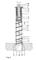
- the screw 1 is inserted into the borehole 24, wherein due to the reduced diameter of the screw 1 at the insertion end 3, the screw 1 at least partially penetrates into the borehole 24.
- the screw 1 rests with the cutting elements 9, which are arranged along the external thread 8 within the borehole 24, against an inner wall 19 of the borehole 24 without a cutting process taking place.
- the core 2 is pressed against the inner wall 19 on the side of the core 2 opposite the cutting element 9 which initially engages the inner wall 19 of the borehole 24.
- the support element 17 accordingly causes a support of the screw 1 in the borehole 24 and prevents the screw 1 from tipping about the central longitudinal axis 7 of the screw 1 as a result of the engagement of the cutting element 9 with the inner wall 19 of the borehole 24 , Thus, damage to the screw 1 and a milling of the borehole 24 is avoided.
- the screw 1 is thus securely supported by the support element 17 in the borehole 24 and guided and centered in particular during the screwing start.
- the support elements 17 thus act as centering and Einschraub Anlagen.
- Fig. 3 the screwing for the screwed completely into the borehole 24 screw 1 described in more detail.
- the screw 1 with the screw-in tool 26 along the screwing direction 5 is screwed further into the wellbore 24.
- a trained as an internal thread support thread 20 is cut into the inner wall 19 of the borehole 24 by the cutting elements 9.
- the support thread 20 serves to fasten the screw 1 in the borehole 24, in which the external thread 8 is arranged in the carrying thread 20.
- the remaining along the inner wall 19 between the support thread 20, helical ridge 21 is as well as the support thread 20 despite the provided on the core 2 support elements 17 undamaged, so that the carrying capacity of the screw of the screw 1 in the borehole 24 against a Screw without support elements 17 is not affected.
- the reason for this is that the support element diameter D St is smaller than the thread diameter D G and thus, after the screw 1 itself centered after the screwing by means of the support elements 17 and the cutting elements 9 and in the borehole 24 has been cut, the support elements 17 do no cutting work on the inner wall 19.
Landscapes
- Engineering & Computer Science (AREA)
- General Engineering & Computer Science (AREA)
- Mechanical Engineering (AREA)
- Physics & Mathematics (AREA)
- Geometry (AREA)
- Joining Of Building Structures In Genera (AREA)
Description
- Die Erfindung betrifft eine selbstzentrierende Schraube zum Einschrauben in ein Bohrloch in einen harten Werkstoff, insbesondere Beton.
- Die
DE 299 17 000 U1 offenbart eine gewindeformende Schraube zum direkten Einschrauben in eine Bohrung, die in Beton, Mauerwerk oder dergleichen eingebracht ist. Eine derartige Schraube umfasst einen zylindrischen Kern, ein einstückig mit dem Kern ausgebildetes Außen-Gewinde und ein am Kern angeordnetes Drehmoment-Übertragungs-Mittel. Weiterhin sind an dem Kern Stütz-Elemente zum Abstützen der Schraube in dem Bohrloch während des Einschraubens vorgesehen. - Befestigungsmittel für einen harten Werkstoff sind beispielsweise in Form von Betonschrauben durch offenkundige Vorbenutzung bekannt. Derartige Schrauben weisen einen zylindrischen Kern mit einem Kern-Durchmesser und einem Einführende auf, dessen Durchmesser gegenüber dem Kern-Durchmesser reduziert ist. Beim Einführen der Schraube mit dem Einführende in ein Bohrloch kommt es zum Anlegen eines Außen-Gewindes der Schraube an einer Innenwand des Bohrlochs in einem Bereich eines Gewindeanfangs. Beim Drehen der Schraube in einer Einschraub-Richtung kann es passieren, dass die Schraube beim Kontakt des Außen-Gewindes mit der Innenwand des Bohrlochs um eine Mittel-Längs-Achse der Schraube kippt. Dadurch kann das Gewinde der Schraube nicht in das Bohrloch eingedreht werden. Die Schraube fasst nicht. Ganz im Gegenteil kommt es zu einem Durchdrehen und zu einem Beschädigen der Schraube sowie einem Ausfräsen des Bohrlochbeginns. Sowohl die Schraube als auch das Bohrloch können dadurch unbrauchbar sein. Das Problem des Einschraubens mit einer derartigen Schraube wird zusätzlich dadurch erschwert, dass oftmals harte Zuschlagsstoffe wie Kiesel und/oder Armierungen in dem harten Werkstoff vorliegen.
- Der Erfindung liegt die Aufgabe zugrunde, eine Schraube zum Einschrauben in ein Bohrloch in einen harten Werkstoff, insbesondere Beton, derart weiterzuentwickeln, dass der Einschraubvorgang verbessert ist.
- Die Aufgabe wird durch die Merkmale des Anspruchs 1 gelöst. Der Kern der Erfindung besteht darin, dass die Schraube mindestens ein Stütz-Element zum Abstützen der Schraube in dem Bohrloch während des Einschraubens aufweist. Dadurch wird verhindert, dass beim Einschrauben der Schraube diese um die Mittel-Längs-Achse kippt. Das mindestens eine Stütz-Element wirkt also als Zentrierhilfe. Die erfindungsgemäße Schraube ist selbstzentrierend während des Einschraubvorgangs. Die erfindungsgemäße Schraube umfasst einen zylindrischen Kern mit einem Einführende, einem diesem gegenüberliegenden Außenende, einem Kern-Durchmesser, einer Einschraub-Richtung und einer dazu parallelen Mittel-Längs-Achse. Weiterhin ist ein mit dem Kern einstückig ausgebildetes, sich entlang eines Gewinde-Abschnitts erstreckendes Außen-Gewinde zum Einschrauben desselben in den Werkstoff vorgesehen. Das Außen-Gewinde weist einen Gewinde-Durchmesser, einen am Einführende angeordneten Gewindeanfang und mindestens ein Schneid-Element zum Einschneiden des Außen-Gewindes in den Werkstoff auf. Zum Einschrauben der Schraube in den Werkstoff ist an dem Kern ein Drehmoment-Übertragungs-Mittel zur Übertragung eines Einschraub-Drehmoments von einem Einschraub-Werkzeug auf den Kern der Schraube angeordnet. Das mindestens eine Stütz-Element ist im Bereich des Gewindeanfangs angeordnet und bezogen auf die Mittel-Längs-Achse dem mindestens einen Schneid-Element diametral gegenüberliegend an dem Kern angeordnet. Dadurch ist gewährleistet, dass beim Eingreifen des Schneid-Elements in den harten Werkstoff die Schraube an einer dem Schneid-Element gegenüberliegenden Seite in dem Bohrloch abgestützt und somit sicher geführt ist. Das mindestens eine Stütz-Element kann als eine von dem Kern hervorstehende Erhebung ausgeführt sein. Insbesondere in dem Fall, dass es sich um eine sprödbruchfreie Schraube handelt, kann das mindestens eine Stütz-Element als aufgeschweißter Schneidstift ausgeführt sein. Für den Fall, dass es sich um eine Edelstahlschraube handelt, können die besonders hart ausgeführten Schneidstifte in dafür vorgesehenen Bohrungen in der Schraube verankert sein. Es ist auch denkbar, auf den Kern der Schraube ein spitz zulaufendes Zwischengewinde, das dem Außen-Gewinde diametral gegenüberliegend angeordnet ist, vorzusehen. Das mindestens eine Stütz-Element kann gemäß einer bevorzugten Ausführungsform entlang einer Schraubenlinie an dem Kern angeordnet sein, wobei die Schraubenlinie höchstens einen Gewindegang, insbesondere höchstens 80% eines Gewindegangs und insbesondere höchstens 50% eines Gewindegangs umfasst. In Folge der schraubenlinienförmigen Anordnung der Stütz-Elemente ist gewährleistet, dass entlang eines größeren Einschraubwinkelbereichs eine Abstützung der Schraube in dem Bohrloch erfolgt. Durch eine Begrenzung der Höhe der Schraubenlinie kann vermieden werden, dass der Eindrehwiderstand der Schraube mit steigender Einschraubtiefe unnötig ansteigt. Somit kann verhindert werden, dass in Folge eines unzulässig hohen Eindrehwiderstands ein Kraftbedarf zum Einschrauben überproportional ansteigt und beispielsweise die Schraube in dem Bohrloch abgedreht wird. Weiterhin wird verhindert, dass ein zwischen den Traggewinden in dem Bohrloch verbleibender Steg beschädigt wird und daraus ein Tragfähigkeitsverlust bei einer Zugbelastung der eingeschraubten Schraube auftreten könnte. Es ist insbesondere von Vorteil, wenn die Schraubenlinie und das Außen-Gewinde identische Gewindesteigungen aufweisen, sodass in Folge des Einschraubens die Mittel-Längs-Achse der Schraube auch mit zunehmender Einschraubtiefe im Bohrloch zentriert ist. Die Schraube kann an einem Schneid-Element einen Schneid-Element-Durchmesser aufweisen, der größer ist als der Gewinde-Durchmesser. Entsprechend kann die Schraube an dem mindestens einen Stütz-Element einen Stütz-Element-Durchmesser aufweisen, der kleiner ist als der Gewinde-Durchmesser. Dadurch, dass der Schneid-Element-Durchmesser größer ist als der Gewinde-Durchmesser wird das Einschneiden der Schraube in den harten Werkstoff erleichtert. Dadurch, dass der Stütz-Element-Durchmesser kleiner ist als der Gewinde-Durchmesser ist gewährleist, dass ein in dem Bohrloch verbleibender Betonsteg zwischen dem Trag-Gewinde nicht geschädigt wird und somit die Tragfähigkeit der in das Bohrloch eingeschraubten Schraube verbessert ist.
- Weitere vorteilhafte Ausgestaltungen der Erfindung ergeben sich aus den Unteransprüchen.
- Zusätzliche Merkmale und Einzelheiten der Erfindung ergeben sich aus der nachfolgenden Beschreibung eines Ausführungsbeispiels anhand der Zeichnung. Es zeigen:
- Fig. 1
- eine teilgeschnittene Seitenansicht einer erfindungsgemäßen Schraube,
- Fig. 2
- eine Darstellung eines Einschraubvorgangs der Schraube in ein Bohrloch und
- Fig. 3
- eine Darstellung der in das Bohrloch vollständig eingeschraubten Schraube.
- Im Folgenden wird unter Bezugnahme auf die
Fig. 1 der Aufbau einer erfindungsgemäßen selbstzentrierenden Schraube 1 beschrieben. Die Schraube 1 ist zum Einschrauben in ein Bohrloch in einen harten Werkstoff, insbesondere, Beton mit einer Betonfestigkeit von mindestens C30 oder andere harte Natursteine, wie zum Beispiel Sandstein oder Granit, geeignet. Die Schraube 1 kann auch für weichere Werkstoffe eingesetzt werden. - Die Schraube 1 weist einen im Wesentlichen zylindrischen Kern 2 mit einem Einführende 3, einem diesen gegenüberliegenden Außenende 4, einer Einschraub-Richtung 5, einem Außenumfang 6 und einer parallel zur Einschraub-Richtung 5 verlaufenden Mittel-Längs-Achse 7 auf. Einstückig mit dem Kern 2 ist ein Außen-Gewinde 8 ausgebildet, das sich vom Einführende 3 entgegen der Richtung 5 entlang eines Gewinde-Abschnitts der Länge AG erstreckt. Das Außen-Gewinde 8 ist entlang eines sich vom Einführende 3 entgegen der Einschraub-Richtung 5 erstreckenden Schneid-Abschnitts der Länge AS selbstschneidend und weist hierfür mindestens ein Schneid-Element an dem Außen-Gewinde 8 auf. Der Kern 2 weist einen Kern-Durchmesser DK und das Außen-Gewinde 8 einen Gewinde-Durchmesser DG auf, wobei der Gewinde-Durchmesser DG größer ist als der Kern-Durchmesser DK.
- An den Schneid-Abschnitt AS schließt sich ein Normal-Gewinde-Abschnitt der Länge AN an, in dem keine Schneid-Elemente 9 an dem Außen-Gewinde 8 vorgesehen sind. Entsprechend gilt: AS + AN = AG. An den Gewinde-Abschnitt AG schließt sich ein kreiszylindrischer Zylinder-Abschnitt der Länge AZ an, der eine im Wesentlichen glatte Oberfläche aufweist. An den Zylinder-Abschnitt AZ schließt sich ein sich bis zum Außenende 4 erstreckender Kragenabschnitt AK an, der nachfolgend näher beschrieben ist. Der Kern 2 verjüngt sich ungefähr entlang der Höhe HG eines Gewindegangs im Bereich des Einführendes 3 in der Form eines Kegelabschnitts. Die Gesamtlänge L der Schraube 1 setzt sich zusammen aus AG + AZ + AK.
- Im Bereich des Außenendes 4 ist ein konzentrisch zur Mittel-Längs-Achse 7 entgegen der Einschraub-Richtung 5 offenes Sackloch 10 angeordnet. Beginnend vom Außenende 4 weist das Sackloch 10 ein Innen-Gewinde 11 auf. Bei dem Innen-Gewinde 11 handelt es sich vorzugsweise um ein normales Metallgewinde. Das Innen-Gewinde 11 erstreckt sich nur über einen Teil, z.B. ¾ der Tiefe des Sacklochs 10. Das Innen-Gewinde 11 dient beispielsweise für ein Befestigungs-Element, das an der Schraube 1 einschraubbar ist. Somit ist es möglich, die Schraube 1 als BefestigungsAnker in einem harten Werkstoff wie beispielsweise Beton zu verwenden. In Richtung 5 hinter dem Innen-Gewinde 11 weist die Wand des Sacklochs 10 die Form eines Innen-Sechskants 12 auf, wobei der maximale InnenDurchmesser des Innen-Sechskants 12 kleiner ist als der InnenDurchmesser des Innen-Gewindes 11. Anstelle des Innen-Sechskants 12 können auch andere unrunde Querschnitte verwendet werden. Im Bereich des Außenendes 4 weist der Kern 2 einen gegenüber dem Kern 2 radial vorspringenden, einteilig mit dem Kern 2 ausgebildeten Kragen 13 auf. Der Kragen 13 weist entgegen der Richtung 5 eine ebene, senkrecht zur Achse 7 verlaufende Stirnfläche 14 auf. Die axiale Dicke des Kragens 13 reduziert sich mit zunehmendem radialen Abstand, d.h. der Kragen 13 wird begrenzt durch die Stirnfläche 14 und eine schräg zu dieser verlaufenden Flankenfläche 15, wobei sich beide unter einem spitzen Winkel schneiden. Es ist grundsätzlich möglich, den Querschnitt des Kragens 13 anders zu gestalten, z.B. scheibenförmig. Im Bereich des Außenendes 4 kann zum Eindrehen der Schraube 1 auch ein Sechskantkopf oder ein anderes Mittel zur Drehmomentübertragung angebracht sein.
- Der Kragen 13 weist einen Außen-Durchmesser DKR auf. Der Kern 2 weist einen Außen-Durchmesser DKE auf. Es gilt: DKR / DKE ≥ 1,2, insbesondere ≥ 1,3, insbesondere ≥ 1,5.
- Das Außen-Gewinde 8 weist einen Gewindeanfang 16 auf, der am Einführende 3 angeordnet ist. Weiterhin sind an dem Kern 2 mehrere Stützelemente 17 zum Abstützen der Schraube 1 in einem Bohrloch während eines Einschraubvorgangs vorgesehen. Die Stütz-Elemente 17 sind im Bereich des Gewindeanfangs 16 angeordnet und bezogen auf die Mittel-Längs-Achse 7 diametral gegenüberliegend zu den Schneid-Elementen 9 an dem Kern 2 angeordnet. Gemäß dem gezeigten Ausführungsbeispiel ist das Stütz-Element als aufgeschweißter Schneidstift ausgeführt. Es ist auch möglich, die Schneidstifte in Bohrungen an der Schraube 1, beispielsweise bei einer Edelstahlschraube, zu verankern. Für den Fall, dass die Stütz-Elemente 17 in Form der verankerten oder aufgeschweißten Schneidstifte ausgeführt sind, werden diese nach ihrer Anbringung an dem Kern 2 der Schraube 1 abschließend derart überschliffen, dass sie ein spitz zulaufendes Gewinde ausbilden. Es ist auch denkbar, auf die Schraube 1 ein spitz zulaufendes Zwischengewinde aufzuwalzen.
- Die Stütz-Elemente 17 sind entlang einer Schraubenlinie 18 an dem Kern 2 angeordnet. Gemäß dem gezeigten Ausführungsbeispiel umfasst die Schraubenlinie 18 genau einen Gewindegang der Gewindehöhe HG. Es ist auch möglich, dass die Schraubenlinie 18 höchstens 80% des Gewindegangs HG und insbesondere höchstens 50% des Gewindegangs HG umfasst. Dadurch, dass die Stütz-Elemente 17 jeweils genau einem Schneid-Element 9 zugeordnet und diesem diametral gegenüberliegend angeordnet sind, ist entsprechend die Schraubenlinie 18 insgesamt dem Außen-Gewinde 8 bezüglich der Mittel-Längs-Achse 7 diametral gegenüberliegend angeordnet. Entsprechend weisen die Schraubenlinie 18 und das Außen-Gewinde 8 identische Gewindesteigungen auf. Im Bereich der Schneid-Elemente 9 weist die Schraube 1 einen Schneid-Element-Durchmesser DSch auf, der größer ist als der Gewinde-Durchmesser DG. Im Bereich der Stütz-Elemente 17 weist die Schraube einen Stütz-Element-Durchmesser DSt auf, der kleiner ist als der Gewinde-Durchmesser DG. Der Innen-Sechskant 12 dient als Drehmoment-Übertragungs-Mittel zur Übertragung eines Einschraub-Drehmoments von einem Einschraub-Werkzeug 26 auf den Kern 2 zum Einschrauben desselben in den Werkstoff. Es ist auch möglich, das Drehmoment-Übertragungs-Mittel in einer anderen Form auszuführen, beispielsweise als einen auf den Kern 2 aufgesetzten, über den Kern-Durchmesser DK hinausragenden Schraubenkopf mit beispielsweise einem Querschnitt in Form eines Außen-Sechskants. Andere, gängige Drehmoment-Übertragungs-Mittel sind ebenfalls möglich.
- Im Folgenden wird anhand der
Fig. 2 der Beginn eines Einschraubvorgangs der erfindungsgemäßen, selbstzentrierenden Schraube 1 in ein Bohrloch 24 näher erläutert. Zunächst wird die Schraube 1 in das Bohrloch 24 eingesetzt, wobei aufgrund des reduzierten Durchmessers der Schraube 1 am Einführende 3 die Schraube 1 zumindest teilweise in das Bohrloch 24 eindringt. Die Schraube 1 liegt mit den Schneid-Elementen 9, die entlang des Außen-Gewindes 8 innerhalb des Bohrlochs 24 angeordnet sind, an einer Innenwand 19 des Bohrlochs 24 an, ohne dass ein Schneidvorgang stattfindet. Durch Drehen der Schraube 1 mit einem Einschraub-Werkzeug 26 entlang der Einschraub-Richtung 5 wird der Kern 2 auf der dem zuerst in die Innenwand 19 des Bohrlochs 24 eingreifenden Schneidelements 9 gegenüberliegenden Seite des Kerns 2 gegen die Innenwand 19 gepresst. Das Stütz-Element 17 bewirkt dementsprechend eine Abstützung der Schraube 1 in dem Bohrloch 24 und verhindert, dass die Schraube 1 infolge des Eingriffs des Schneid-Elements 9 mit der Innenwand 19 des Bohrlochs 24 um die Mittel-Längs-Achse 7 der Schraube 1 kippt. Somit wird eine Beschädigung der Schraube 1 und ein Ausfräsen des Bohrlochs 24 vermieden. Die Schraube 1 ist somit durch das Stütz-Element 17 sicher in dem Bohrloch 24 abgestützt und insbesondere während des Einschraubbeginns sicher geführt und zentriert. Die Stütz-Elemente 17 wirken also als Zentrier- und Einschraubhilfe. Es gibt für das Einschrauben in Beton geeignete Schrauben 1, die keine Schneidzähne aufweisen bzw. eingewalzte Schneidzähne besitzen. Auch bei diesen funktioniert der oben erläuterte Beginn des Einschraubvorgangs gleichermaßen, solange die als Zentrierhilfe wirkenden Stütz-Elemente 17 gegenüber der ersten Gewinde-Steigung liegen. - Im Folgenden wird anhand der
Fig. 3 der Einschraubvorgang für die vollständig in das Bohrloch 24 eingeschraubte Schraube 1 näher beschrieben. Ausgehend von der Darstellung inFig. 2 wird die Schraube 1 mit dem Einschraub-Werkzeug 26 entlang der Einschraub-Richtung 5 weiter in das Bohrloch 24 eingeschraubt. Dabei ist in die Innenwand 19 des Bohrlochs 24 durch die Schneid-Elemente 9 ein als Innen-Gewinde ausgebildetes Trag-Gewinde 20 eingeschnitten. Das Trag-Gewinde 20 dient der Befestigung der Schraube 1 in dem Bohrloch 24, in dem das Außen-Gewinde 8 in dem Trag-Gewinde 20 angeordnet ist. Der entlang der Innenwand 19 zwischen dem Trag-Gewinde 20 verbleibende, schraubenlinienförmige Steg 21 ist ebenso wie das Trag-Gewinde 20 trotz der am Kern 2 vorgesehenen Stütz-Elemente 17 unbeschädigt, sodass die Tragfähigkeit der Schraubverbindung der Schraube 1 in dem Bohrloch 24 gegenüber einer Schraube ohne Stütz-Elemente 17 nicht beeinträchtigt ist. Der Grund hierfür ist, dass der Stütz-Element-Durchmesser DSt kleiner ist als der Gewinde-Durchmesser DG und somit, nachdem die Schraube 1 sich nach dem Einschraubvorgang mittels der Stütz-Elemente 17 und der Schneid-Elemente 9 selbst zentriert und in das Bohrloch 24 eingeschnitten hat, die Stütz-Elemente 17 keine Schneidarbeit an der Innenwand 19 leisten.
Claims (12)
- Selbstzentrierende Schraube zum Einschrauben in ein Bohrloch in einen harten Werkstoff, insbesondere Beton, wobei die Schraube (1) umfassta. einen zylindrischen Kern (2) miti. einem Einführende (3),ii. einem diesem gegenüberliegenden Außenende (4),iii. einem Kern-Durchmesser (DK),iv. einer Einschraub-Richtung (5) undv. einer dazu parallelen Mittel-Längs-Achse (7),b. ein einstückig mit dem Kern (2) ausgebildetes, sich entlang eines Gewinde-Abschnitts (AG) erstreckendes Außen-Gewinde (8) zum Einschrauben desselben in den Werkstoff miti. einem Gewinde-Durchmesser (DG),ii. einem am Einführende (3) angeordneten Gewindeanfang (16) undiii. mindestens ein Schneid-Element (9) zum Einschneiden des Außen-Gewindes (8) in den Werkstoff,c. ein am Kern (2) angeordnetes Drehmoment-Übertragungs-Mittel (12) zur Übertragung eines Einschraub-Drehmoments von einem Einschraub-Werkzeug (26) auf den Kern (2) zum Einschrauben desselben in den Werkstoff undd. mindestens ein Stütz-Element (17) zum Abstützen der Schraube (1) in dem Bohrloch (24) während des Einschraubens,wobei das mindestens eine Stütz-Element (17) im Bereich des Gewindeanfangs (16) und bezogen auf die Mittel-Längs-Achse (7) dem mindestens einen Schneid-Element (9) im Wesentlichen gegenüberliegend, insbesondere diametral gegenüberliegend, an dem Kern (2) angeordnet ist,
dadurch gekennzeichnet, dass das mindestens eine Stütz-Element (17) eine andere Materialzusammensetzung aufweist als der Kern (2) und/oder als das Außengewinde. - Schraube gemäß Anspruch 1, dadurch gekennzeichnet, dass das mindestens eine Stütz-Element (17) als eine von dem Kern (2) hervorstehende Erhebung, insbesondere als aufgeschweißte Erhebung oder Schneidstift, ausgeführt ist.
- Schraube gemäß einem der vorstehenden Ansprüche, gekennzeichnet durch mehrere, am Kern (2) entlang einer Schraubenlinie (18) angeordnete Stütz-Elemente (17).
- Schraube gemäß Anspruch 3, dadurch gekennzeichnet, dass die Schraubenlinie (18) höchstens einen Gewindegang (HG), insbesondere höchstens 80% des Gewindegangs (HG) und insbesondere höchstens 50% des Gewindegangs (HG)umfasst.
- Schraube gemäß Anspruch 3 oder 4, dadurch gekennzeichnet, dass die Schraubenlinie (18) und das Außen-Gewinde (8) bezüglich der Mittel-Längs-Achse (7) diametral gegenüberliegend angeordnet sind.
- Schraube gemäß einem der Ansprüche 3 bis 5, dadurch gekennzeichnet, dass die Schraubenlinie (18) und das Außen-Gewinde (8) identische Gewindesteigungen aufweisen.
- Schraube gemäß einem der vorstehenden Ansprüche, gekennzeichnet durch einen Schneid-Element-Durchmesser (DSch), der größer ist als der Gewinde-Durchmesser (DG).
- Schraube gemäß Anspruch 5 gekennzeichnet durch einen Stütz-Element-Durchmesser (DSt), der kleiner ist als der Gewinde-Durchmesser (DG).
- Schraube gemäß einem der Ansprüche 1 oder 2, dadurch gekennzeichnet, dass mindestens ein Stütz-Element (17) stegförmig, insbesondere in Form eines Gewindeabschnitts ausgebildet ist.
- Schraube gemäß einem der Ansprüche 1 oder 2, dadurch gekennzeichnet, dass die Höhe des mindestens einen Stütz-Elements (17) gegenüber dem Kern (2) kleiner gleich, insbesondere kleiner, insbesondere 10%, insbesondere 20%, insbesondere 30% kleiner als die Höhe des Außen-Gewindes (8) gegenüber dem Kern (2) ist.
- Schraube gemäß einem der Ansprüche 1 oder 2, dadurch gekennzeichnet, dass gesehen vom Einführende (3) entlang der Mittel-Längs-Achse (7) das erste Stütz-Element (17) vom Einführende (3) ungefähr denselben Abstand hat wie der Gewindeanfang (16).
- Schraube gemäß Anspruch 1 oder 2, dadurch gekennzeichnet, dass das mindestens eine Stütz-Element (17) in der Form als Gewindeabschnitt ausgebildet ist mit einem angularen Winkel bezogen auf die Mittel-Längs-Achse (7) größer gleich 45°, insbesondere größer gleich 90°, insbesondere größer gleich 120°, insbesondere größer gleich 180°.
Applications Claiming Priority (2)
| Application Number | Priority Date | Filing Date | Title |
|---|---|---|---|
| DE201010031410 DE102010031410A1 (de) | 2010-07-15 | 2010-07-15 | Selbstzentrierende Schraube |
| PCT/EP2011/061580 WO2012007368A1 (de) | 2010-07-15 | 2011-07-08 | Selbstzentrierende schraube |
Publications (2)
| Publication Number | Publication Date |
|---|---|
| EP2593683A1 EP2593683A1 (de) | 2013-05-22 |
| EP2593683B1 true EP2593683B1 (de) | 2014-06-11 |
Family
ID=44583536
Family Applications (1)
| Application Number | Title | Priority Date | Filing Date |
|---|---|---|---|
| EP11733828.5A Active EP2593683B1 (de) | 2010-07-15 | 2011-07-08 | Selbstzentrierende schraube |
Country Status (3)
| Country | Link |
|---|---|
| EP (1) | EP2593683B1 (de) |
| DE (1) | DE102010031410A1 (de) |
| WO (1) | WO2012007368A1 (de) |
Families Citing this family (3)
| Publication number | Priority date | Publication date | Assignee | Title |
|---|---|---|---|---|
| DE102015216237A1 (de) * | 2015-08-25 | 2017-03-02 | Toge Dübel Gmbh & Co. Kg | Schraube zum Einschrauben in ein Bohrloch und Anordnung mit einer derartigen Schraube |
| DE102018114983A1 (de) | 2018-06-21 | 2019-12-24 | Ejot Gmbh & Co. Kg | Selbstfurchende Schraube |
| DE102022121434A1 (de) * | 2022-08-24 | 2024-02-29 | Ejot Se & Co. Kg | Schraube für die Direktverschraubung in ein Bauteil |
Family Cites Families (8)
| Publication number | Priority date | Publication date | Assignee | Title |
|---|---|---|---|---|
| US3426642A (en) * | 1962-02-05 | 1969-02-11 | Res Eng & Mfg | Self-tapping screws with threadforming projections |
| SE398149B (sv) * | 1975-06-05 | 1977-12-05 | Bulten Kanthal Ab | Sjelvgengande skruv |
| US5190426A (en) * | 1992-03-02 | 1993-03-02 | Illinois Tool Works Inc. | Concrete fastener |
| DE4419988A1 (de) * | 1994-06-08 | 1995-12-14 | Eichsfelder Schraubenwerk Gmbh | Gewindeformende Schraube |
| DE29621923U1 (de) * | 1996-12-17 | 1998-04-16 | Mitek Ind Gmbh | Holztragwerkverbindungssystem |
| DE29917000U1 (de) * | 1999-09-28 | 1999-12-23 | Rensburg, Markus, Dipl.-Wirtsch.-Ing., 58093 Hagen | Gewindeformende Schraube |
| DE10243537A1 (de) * | 2002-09-16 | 2004-03-25 | Adolf Würth GmbH & Co. KG | Gewindebildende Schraube |
| JP2008291870A (ja) * | 2007-05-22 | 2008-12-04 | Hilti Ag | タッピンねじ |
-
2010
- 2010-07-15 DE DE201010031410 patent/DE102010031410A1/de not_active Withdrawn
-
2011
- 2011-07-08 EP EP11733828.5A patent/EP2593683B1/de active Active
- 2011-07-08 WO PCT/EP2011/061580 patent/WO2012007368A1/de not_active Ceased
Also Published As
| Publication number | Publication date |
|---|---|
| EP2593683A1 (de) | 2013-05-22 |
| DE102010031410A1 (de) | 2012-01-19 |
| WO2012007368A1 (de) | 2012-01-19 |
Similar Documents
| Publication | Publication Date | Title |
|---|---|---|
| DE10130681B4 (de) | Selbstbohrende Blindnietmutter | |
| EP2273134B1 (de) | Gewindefurchende Schraube | |
| EP3719330B1 (de) | Schraube mit diskontinuität an zwischengewindeabschnitt | |
| EP1001178A2 (de) | Gasbeton-Schraube | |
| EP3033533B1 (de) | Betonschraube | |
| EP3726072B1 (de) | Schraube für holzwerkstoffe | |
| DE102006000539A1 (de) | Befestigungselement | |
| EP2593683A1 (de) | Selbstzentrierende schraube | |
| EP3380737B1 (de) | Betonschraube | |
| EP2224142B1 (de) | Gewindeformende Schraube | |
| EP4166798B1 (de) | Selbstschneidende schraube | |
| EP2844884B1 (de) | Schraube für leichtbaustoffe | |
| EP1907714B1 (de) | Gewindeschneidender betonanker | |
| EP2308403B1 (de) | Knochenschraube sowie System | |
| EP0930437B1 (de) | Gewindeschneidende Schraube | |
| EP3135927B1 (de) | Schraube zum einschrauben in ein bohrloch und anordnung mit einer derartigen schraube | |
| EP3620672A1 (de) | Betonschraube | |
| EP2108852B1 (de) | Schraube | |
| EP2261517A1 (de) | Furchschraube | |
| WO2014040943A1 (de) | Schraube und ihre verwendung | |
| EP2143963A1 (de) | Bohrschraube | |
| EP4166797A1 (de) | Verankerungsanordnung und verfahren zum verankern eines verankerungselements in einem werkstoff | |
| DE202024103930U1 (de) | Montageschraube | |
| EP0933539A1 (de) | Gewindeschneidende Schraube | |
| DE29905579U1 (de) | Knochenschraube |
Legal Events
| Date | Code | Title | Description |
|---|---|---|---|
| PUAI | Public reference made under article 153(3) epc to a published international application that has entered the european phase |
Free format text: ORIGINAL CODE: 0009012 |
|
| 17P | Request for examination filed |
Effective date: 20121115 |
|
| AK | Designated contracting states |
Kind code of ref document: A1 Designated state(s): AL AT BE BG CH CY CZ DE DK EE ES FI FR GB GR HR HU IE IS IT LI LT LU LV MC MK MT NL NO PL PT RO RS SE SI SK SM TR |
|
| DAX | Request for extension of the european patent (deleted) | ||
| GRAP | Despatch of communication of intention to grant a patent |
Free format text: ORIGINAL CODE: EPIDOSNIGR1 |
|
| INTG | Intention to grant announced |
Effective date: 20140102 |
|
| GRAS | Grant fee paid |
Free format text: ORIGINAL CODE: EPIDOSNIGR3 |
|
| GRAA | (expected) grant |
Free format text: ORIGINAL CODE: 0009210 |
|
| AK | Designated contracting states |
Kind code of ref document: B1 Designated state(s): AL AT BE BG CH CY CZ DE DK EE ES FI FR GB GR HR HU IE IS IT LI LT LU LV MC MK MT NL NO PL PT RO RS SE SI SK SM TR |
|
| REG | Reference to a national code |
Ref country code: GB Ref legal event code: FG4D Free format text: NOT ENGLISH |
|
| REG | Reference to a national code |
Ref country code: CH Ref legal event code: EP |
|
| REG | Reference to a national code |
Ref country code: IE Ref legal event code: FG4D Free format text: LANGUAGE OF EP DOCUMENT: GERMAN |
|
| REG | Reference to a national code |
Ref country code: AT Ref legal event code: REF Ref document number: 672411 Country of ref document: AT Kind code of ref document: T Effective date: 20140715 |
|
| REG | Reference to a national code |
Ref country code: DE Ref legal event code: R096 Ref document number: 502011003388 Country of ref document: DE Effective date: 20140724 |
|
| PG25 | Lapsed in a contracting state [announced via postgrant information from national office to epo] |
Ref country code: NO Free format text: LAPSE BECAUSE OF FAILURE TO SUBMIT A TRANSLATION OF THE DESCRIPTION OR TO PAY THE FEE WITHIN THE PRESCRIBED TIME-LIMIT Effective date: 20140911 Ref country code: LT Free format text: LAPSE BECAUSE OF FAILURE TO SUBMIT A TRANSLATION OF THE DESCRIPTION OR TO PAY THE FEE WITHIN THE PRESCRIBED TIME-LIMIT Effective date: 20140611 Ref country code: FI Free format text: LAPSE BECAUSE OF FAILURE TO SUBMIT A TRANSLATION OF THE DESCRIPTION OR TO PAY THE FEE WITHIN THE PRESCRIBED TIME-LIMIT Effective date: 20140611 Ref country code: GR Free format text: LAPSE BECAUSE OF FAILURE TO SUBMIT A TRANSLATION OF THE DESCRIPTION OR TO PAY THE FEE WITHIN THE PRESCRIBED TIME-LIMIT Effective date: 20140912 |
|
| REG | Reference to a national code |
Ref country code: NL Ref legal event code: VDEP Effective date: 20140611 |
|
| REG | Reference to a national code |
Ref country code: LT Ref legal event code: MG4D |
|
| PG25 | Lapsed in a contracting state [announced via postgrant information from national office to epo] |
Ref country code: LV Free format text: LAPSE BECAUSE OF FAILURE TO SUBMIT A TRANSLATION OF THE DESCRIPTION OR TO PAY THE FEE WITHIN THE PRESCRIBED TIME-LIMIT Effective date: 20140611 Ref country code: HR Free format text: LAPSE BECAUSE OF FAILURE TO SUBMIT A TRANSLATION OF THE DESCRIPTION OR TO PAY THE FEE WITHIN THE PRESCRIBED TIME-LIMIT Effective date: 20140611 Ref country code: SE Free format text: LAPSE BECAUSE OF FAILURE TO SUBMIT A TRANSLATION OF THE DESCRIPTION OR TO PAY THE FEE WITHIN THE PRESCRIBED TIME-LIMIT Effective date: 20140611 Ref country code: RS Free format text: LAPSE BECAUSE OF FAILURE TO SUBMIT A TRANSLATION OF THE DESCRIPTION OR TO PAY THE FEE WITHIN THE PRESCRIBED TIME-LIMIT Effective date: 20140611 |
|
| REG | Reference to a national code |
Ref country code: DE Ref legal event code: R082 Ref document number: 502011003388 Country of ref document: DE Representative=s name: RAU, SCHNECK & HUEBNER PATENTANWAELTE RECHTSAN, DE |
|
| PG25 | Lapsed in a contracting state [announced via postgrant information from national office to epo] |
Ref country code: PT Free format text: LAPSE BECAUSE OF FAILURE TO SUBMIT A TRANSLATION OF THE DESCRIPTION OR TO PAY THE FEE WITHIN THE PRESCRIBED TIME-LIMIT Effective date: 20141013 Ref country code: EE Free format text: LAPSE BECAUSE OF FAILURE TO SUBMIT A TRANSLATION OF THE DESCRIPTION OR TO PAY THE FEE WITHIN THE PRESCRIBED TIME-LIMIT Effective date: 20140611 Ref country code: SK Free format text: LAPSE BECAUSE OF FAILURE TO SUBMIT A TRANSLATION OF THE DESCRIPTION OR TO PAY THE FEE WITHIN THE PRESCRIBED TIME-LIMIT Effective date: 20140611 Ref country code: RO Free format text: LAPSE BECAUSE OF FAILURE TO SUBMIT A TRANSLATION OF THE DESCRIPTION OR TO PAY THE FEE WITHIN THE PRESCRIBED TIME-LIMIT Effective date: 20140611 Ref country code: ES Free format text: LAPSE BECAUSE OF FAILURE TO SUBMIT A TRANSLATION OF THE DESCRIPTION OR TO PAY THE FEE WITHIN THE PRESCRIBED TIME-LIMIT Effective date: 20140611 Ref country code: CZ Free format text: LAPSE BECAUSE OF FAILURE TO SUBMIT A TRANSLATION OF THE DESCRIPTION OR TO PAY THE FEE WITHIN THE PRESCRIBED TIME-LIMIT Effective date: 20140611 |
|
| PG25 | Lapsed in a contracting state [announced via postgrant information from national office to epo] |
Ref country code: NL Free format text: LAPSE BECAUSE OF FAILURE TO SUBMIT A TRANSLATION OF THE DESCRIPTION OR TO PAY THE FEE WITHIN THE PRESCRIBED TIME-LIMIT Effective date: 20140611 Ref country code: PL Free format text: LAPSE BECAUSE OF FAILURE TO SUBMIT A TRANSLATION OF THE DESCRIPTION OR TO PAY THE FEE WITHIN THE PRESCRIBED TIME-LIMIT Effective date: 20140611 Ref country code: IS Free format text: LAPSE BECAUSE OF FAILURE TO SUBMIT A TRANSLATION OF THE DESCRIPTION OR TO PAY THE FEE WITHIN THE PRESCRIBED TIME-LIMIT Effective date: 20141011 |
|
| REG | Reference to a national code |
Ref country code: CH Ref legal event code: PL |
|
| REG | Reference to a national code |
Ref country code: DE Ref legal event code: R082 Ref document number: 502011003388 Country of ref document: DE Representative=s name: RAU, SCHNECK & HUEBNER PATENTANWAELTE RECHTSAN, DE Effective date: 20150126 Ref country code: DE Ref legal event code: R081 Ref document number: 502011003388 Country of ref document: DE Owner name: TOGE DUEBEL GMBH & CO. KG, DE Free format text: FORMER OWNER: TOGE-DUEBEL A. GERHARD KG, 90431 NUERNBERG, DE Effective date: 20150126 |
|
| REG | Reference to a national code |
Ref country code: DE Ref legal event code: R097 Ref document number: 502011003388 Country of ref document: DE |
|
| PG25 | Lapsed in a contracting state [announced via postgrant information from national office to epo] |
Ref country code: MC Free format text: LAPSE BECAUSE OF FAILURE TO SUBMIT A TRANSLATION OF THE DESCRIPTION OR TO PAY THE FEE WITHIN THE PRESCRIBED TIME-LIMIT Effective date: 20140611 |
|
| PLBE | No opposition filed within time limit |
Free format text: ORIGINAL CODE: 0009261 |
|
| STAA | Information on the status of an ep patent application or granted ep patent |
Free format text: STATUS: NO OPPOSITION FILED WITHIN TIME LIMIT |
|
| REG | Reference to a national code |
Ref country code: IE Ref legal event code: MM4A |
|
| PG25 | Lapsed in a contracting state [announced via postgrant information from national office to epo] |
Ref country code: LI Free format text: LAPSE BECAUSE OF NON-PAYMENT OF DUE FEES Effective date: 20140731 Ref country code: CH Free format text: LAPSE BECAUSE OF NON-PAYMENT OF DUE FEES Effective date: 20140731 Ref country code: DK Free format text: LAPSE BECAUSE OF FAILURE TO SUBMIT A TRANSLATION OF THE DESCRIPTION OR TO PAY THE FEE WITHIN THE PRESCRIBED TIME-LIMIT Effective date: 20140611 |
|
| 26N | No opposition filed |
Effective date: 20150312 |
|
| REG | Reference to a national code |
Ref country code: FR Ref legal event code: CJ Effective date: 20150420 Ref country code: FR Ref legal event code: CD Owner name: TOGE DUBEL GMBH & CO.KG Effective date: 20150420 |
|
| REG | Reference to a national code |
Ref country code: AT Ref legal event code: HC Ref document number: 672411 Country of ref document: AT Kind code of ref document: T Owner name: TOGE DUEBEL GMBH & CO. KG, DE Effective date: 20150422 |
|
| REG | Reference to a national code |
Ref country code: DE Ref legal event code: R097 Ref document number: 502011003388 Country of ref document: DE Effective date: 20150312 |
|
| PG25 | Lapsed in a contracting state [announced via postgrant information from national office to epo] |
Ref country code: SI Free format text: LAPSE BECAUSE OF FAILURE TO SUBMIT A TRANSLATION OF THE DESCRIPTION OR TO PAY THE FEE WITHIN THE PRESCRIBED TIME-LIMIT Effective date: 20140611 |
|
| PG25 | Lapsed in a contracting state [announced via postgrant information from national office to epo] |
Ref country code: IE Free format text: LAPSE BECAUSE OF NON-PAYMENT OF DUE FEES Effective date: 20140708 |
|
| GBPC | Gb: european patent ceased through non-payment of renewal fee |
Effective date: 20150708 |
|
| PG25 | Lapsed in a contracting state [announced via postgrant information from national office to epo] |
Ref country code: GB Free format text: LAPSE BECAUSE OF NON-PAYMENT OF DUE FEES Effective date: 20150708 Ref country code: SM Free format text: LAPSE BECAUSE OF FAILURE TO SUBMIT A TRANSLATION OF THE DESCRIPTION OR TO PAY THE FEE WITHIN THE PRESCRIBED TIME-LIMIT Effective date: 20140611 |
|
| PG25 | Lapsed in a contracting state [announced via postgrant information from national office to epo] |
Ref country code: CY Free format text: LAPSE BECAUSE OF FAILURE TO SUBMIT A TRANSLATION OF THE DESCRIPTION OR TO PAY THE FEE WITHIN THE PRESCRIBED TIME-LIMIT Effective date: 20140611 Ref country code: MT Free format text: LAPSE BECAUSE OF FAILURE TO SUBMIT A TRANSLATION OF THE DESCRIPTION OR TO PAY THE FEE WITHIN THE PRESCRIBED TIME-LIMIT Effective date: 20140611 Ref country code: BG Free format text: LAPSE BECAUSE OF FAILURE TO SUBMIT A TRANSLATION OF THE DESCRIPTION OR TO PAY THE FEE WITHIN THE PRESCRIBED TIME-LIMIT Effective date: 20140611 |
|
| REG | Reference to a national code |
Ref country code: FR Ref legal event code: PLFP Year of fee payment: 6 |
|
| PG25 | Lapsed in a contracting state [announced via postgrant information from national office to epo] |
Ref country code: TR Free format text: LAPSE BECAUSE OF FAILURE TO SUBMIT A TRANSLATION OF THE DESCRIPTION OR TO PAY THE FEE WITHIN THE PRESCRIBED TIME-LIMIT Effective date: 20140611 Ref country code: HU Free format text: LAPSE BECAUSE OF FAILURE TO SUBMIT A TRANSLATION OF THE DESCRIPTION OR TO PAY THE FEE WITHIN THE PRESCRIBED TIME-LIMIT; INVALID AB INITIO Effective date: 20110708 Ref country code: BE Free format text: LAPSE BECAUSE OF FAILURE TO SUBMIT A TRANSLATION OF THE DESCRIPTION OR TO PAY THE FEE WITHIN THE PRESCRIBED TIME-LIMIT Effective date: 20140731 Ref country code: LU Free format text: LAPSE BECAUSE OF NON-PAYMENT OF DUE FEES Effective date: 20140708 |
|
| REG | Reference to a national code |
Ref country code: FR Ref legal event code: PLFP Year of fee payment: 7 |
|
| PG25 | Lapsed in a contracting state [announced via postgrant information from national office to epo] |
Ref country code: MK Free format text: LAPSE BECAUSE OF FAILURE TO SUBMIT A TRANSLATION OF THE DESCRIPTION OR TO PAY THE FEE WITHIN THE PRESCRIBED TIME-LIMIT Effective date: 20140611 |
|
| REG | Reference to a national code |
Ref country code: FR Ref legal event code: PLFP Year of fee payment: 8 |
|
| PG25 | Lapsed in a contracting state [announced via postgrant information from national office to epo] |
Ref country code: AL Free format text: LAPSE BECAUSE OF FAILURE TO SUBMIT A TRANSLATION OF THE DESCRIPTION OR TO PAY THE FEE WITHIN THE PRESCRIBED TIME-LIMIT Effective date: 20140611 |
|
| PGFP | Annual fee paid to national office [announced via postgrant information from national office to epo] |
Ref country code: IT Payment date: 20190723 Year of fee payment: 9 |
|
| PGFP | Annual fee paid to national office [announced via postgrant information from national office to epo] |
Ref country code: AT Payment date: 20200623 Year of fee payment: 10 |
|
| PG25 | Lapsed in a contracting state [announced via postgrant information from national office to epo] |
Ref country code: IT Free format text: LAPSE BECAUSE OF NON-PAYMENT OF DUE FEES Effective date: 20200708 |
|
| REG | Reference to a national code |
Ref country code: AT Ref legal event code: MM01 Ref document number: 672411 Country of ref document: AT Kind code of ref document: T Effective date: 20210708 |
|
| PG25 | Lapsed in a contracting state [announced via postgrant information from national office to epo] |
Ref country code: AT Free format text: LAPSE BECAUSE OF NON-PAYMENT OF DUE FEES Effective date: 20210708 |
|
| PGFP | Annual fee paid to national office [announced via postgrant information from national office to epo] |
Ref country code: FR Payment date: 20220727 Year of fee payment: 12 |
|
| PG25 | Lapsed in a contracting state [announced via postgrant information from national office to epo] |
Ref country code: FR Free format text: LAPSE BECAUSE OF NON-PAYMENT OF DUE FEES Effective date: 20230731 |
|
| PGFP | Annual fee paid to national office [announced via postgrant information from national office to epo] |
Ref country code: DE Payment date: 20250919 Year of fee payment: 15 |