EP2594083B1 - System zur kontrolle einer arbeitsmaschine - Google Patents
System zur kontrolle einer arbeitsmaschine Download PDFInfo
- Publication number
- EP2594083B1 EP2594083B1 EP11739001.3A EP11739001A EP2594083B1 EP 2594083 B1 EP2594083 B1 EP 2594083B1 EP 11739001 A EP11739001 A EP 11739001A EP 2594083 B1 EP2594083 B1 EP 2594083B1
- Authority
- EP
- European Patent Office
- Prior art keywords
- data
- transmission network
- work machine
- data transmission
- sensor
- Prior art date
- Legal status (The legal status is an assumption and is not a legal conclusion. Google has not performed a legal analysis and makes no representation as to the accuracy of the status listed.)
- Active
Links
Images


Classifications
-
- G—PHYSICS
- G16—INFORMATION AND COMMUNICATION TECHNOLOGY [ICT] SPECIALLY ADAPTED FOR SPECIFIC APPLICATION FIELDS
- G16Z—INFORMATION AND COMMUNICATION TECHNOLOGY [ICT] SPECIALLY ADAPTED FOR SPECIFIC APPLICATION FIELDS, NOT OTHERWISE PROVIDED FOR
- G16Z99/00—Subject matter not provided for in other main groups of this subclass
-
- A—HUMAN NECESSITIES
- A01—AGRICULTURE; FORESTRY; ANIMAL HUSBANDRY; HUNTING; TRAPPING; FISHING
- A01B—SOIL WORKING IN AGRICULTURE OR FORESTRY; PARTS, DETAILS, OR ACCESSORIES OF AGRICULTURAL MACHINES OR IMPLEMENTS, IN GENERAL
- A01B79/00—Methods for working soil
- A01B79/005—Precision agriculture
-
- H—ELECTRICITY
- H04—ELECTRIC COMMUNICATION TECHNIQUE
- H04Q—SELECTING
- H04Q9/00—Arrangements in telecontrol or telemetry systems for selectively calling a substation from a main station, in which substation desired apparatus is selected for applying a control signal thereto or for obtaining measured values therefrom
-
- H—ELECTRICITY
- H04—ELECTRIC COMMUNICATION TECHNIQUE
- H04Q—SELECTING
- H04Q2209/00—Arrangements in telecontrol or telemetry systems
- H04Q2209/20—Arrangements in telecontrol or telemetry systems using a distributed architecture
-
- H—ELECTRICITY
- H04—ELECTRIC COMMUNICATION TECHNIQUE
- H04Q—SELECTING
- H04Q2209/00—Arrangements in telecontrol or telemetry systems
- H04Q2209/40—Arrangements in telecontrol or telemetry systems using a wireless architecture
Definitions
- the invention relates to a system and a method for controlling a work machine.
- Embedded systems for the control of machinery are by definition those which are highly integrated in the environment of their application.
- This issue statement includes a central core aspect: The system must have ways to record the relevant environmental parameters (state variables) in order to then initiate a desired reaction in return.
- sensor arrangements are used which measure a specific size and convert it directly or indirectly into an electrically usable signal.
- the sensor arrays have different outputs, units of measure, and scale formats.
- a good example of this is the vehicle speed. This can be represented at the sensor output as voltage, resistance, pulses per unit of time or as digital value.
- various other units of measure or scales such as e.g. km / h, m / s, mph or similar. or a static bias used.
- various types of information mapping e.g., amplitude modulation
- a transfer of measured values of different sensors into a uniform presentation format is essential, in particular in the context of sensor fusion approaches.
- the output values are mathematically combined as many existing sensors as possible, which map the same physical quantity (ideally using different measurement principles), to increase the accuracy and reliability of the measurement beyond the level of performance of a single sensor.
- the US Pat. No. 7,581,434 B1 describes an arrangement for detecting the state of a device or a liquid, which melts measured values of different sensors.
- a communication system for a vehicle is described in which data is transmitted wirelessly and in a standard format to the vehicle.
- a power line network is described in which message concentrators are present in substations, which are fed by process modules electrical measurements (power, voltage, etc.) of the substation.
- message concentrator parameterisable lists are stored during commissioning of the plant, which assign message numbers to the individual terminals of the process modules.
- the measured values are identified by the message numbers.
- the measured values are transmitted in SI units and the physical dimension is also transmitted.
- the object underlying the invention is seen to avoid or reduce the mentioned disadvantages.
- the system and method presented below makes it possible to adapt the existing information of the sensor arrangements to a uniform format for static as well as dynamically variable sensor configurations of the system without explicit local prior knowledge in a particularly agricultural machine.
- the formatting data required for this purpose are obtained at runtime via a data transmission network which connects sensor arrangements to a processor unit which carries out the alignment and merging of the measured values of the respectively identical or different sensor arrangements.
- a system-wide unique identification feature in the form of an identification number of the sensor arrangement is known.
- the actual formatting data can be stored both locally and remotely in the data transmission network. There they are then accessible, if necessary, in order to transfer data transmitted via the data transmission network sensor readings in a uniform and comparable format.
- the formatting data needed to translate the values of the sensor array into data that can be compared to data from other sensor arrays must be made accessible to the system.
- an identification number is transmitted at the beginning or after connecting a working device to the working machine once from each sensor arrangement, which allows the system to uniquely assign the sensor arrangement.
- the processor unit now queries whether local knowledge is present (ie the system already knows the sensor arrangement).
- the formatting data is retrieved, for example, from a memory unit of the sensor array or a separate memory unit. If this is not the case, the corresponding data is procured decentrally via a wireless data transmission network that provides a connection to external computers.
- a suitable example is a data transmission network that does it Service providers) allows to exchange data. If any participant (eg another tractor or a server of the device manufacturer) already has the required information, it can be made available to all other units connected to the data transmission network.
- data sets in XML format are ideally suited, as they allow the required content to be stored and exchanged in a compact, structured and easily accessible form. Furthermore, however, other data formats are conceivable.
- the presented approach allows to dynamically adapt to new (unknown to the local system) data acquisition sources. This makes it possible to make all existing in the overall system sensor arrangements available to the system. This represents a decisive advantage, especially in the field of agricultural machinery, since this procedure, for example by using the sensors of the implement, allows a higher accuracy of the detection of the physical measured variables. Furthermore, this also reduces the number of sensor arrangements in the overall system (since sensors only have to be present once instead of having to hold them twice in the tractor and implement, for example). This can save costs.
- Other data combination approaches allow on the basis of this extended data base to close on previously inaccessible measures. The formatting data can be stored at the factory or learned during operation of the respective or another working machine.
- the combined measured value provided by the processor unit can serve, in particular, to actuate actuators of a working machine and / or of a working device.
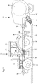
- FIG. 1 shows a side view of an agricultural work machine 10 in the form of a tractor and a means of a drawbar 14 to a towing hitch (not shown) of the working machine 10 coupled, known per se (s. EP 0 316 506 A1 ) Implement 12 in the form of a round baler with a constant or variable Presscrogone.
- the work machine 10 is based on a supporting frame 18 which is supported on steerable front wheels 20 and driven rear wheels 22 and carries a cab 24 in which an operator workstation 26 is located.
- the work machine 10 includes a control unit 30 which serves to control the propulsion speed of the work machine 10 and controls the gear ratio of a transmission 32 driven by an engine 32 (not shown) for driving the rear wheels 22.
- a control unit 30 which serves to control the propulsion speed of the work machine 10 and controls the gear ratio of a transmission 32 driven by an engine 32 (not shown) for driving the rear wheels 22.
- the rotational speed of the internal combustion engine 32 and the speed selectable in stages of a power take-off shaft 34 for driving the driven elements of the working device 12 remain at least approximately constant.
- the control unit 30 is connected via a data transmission network 36 in the form of a bus to various sensor arrangements 38, 40, 42.
- a first sensor arrangement 38 comprises a camera which looks at the swath in front of the work machine 10 and an image processing system 52 which derives the cross-sectional volume of the swath from the image of the camera.
- a second sensor assembly 40 is disposed aboard the implement 12 and senses the drive torque of a rotor 44 that conveys crop material downstream of a picker 46 into a bale forming chamber 48.
- a third sensor arrangement 42 is located on board the work machine 10 and detects the drive torque of the PTO 34.
- the control unit 30 in turn controls the propulsion speed of the work machine 10 in such a way that automatically a desired, constant crop intake rate of the implement 12 is achieved.
- FIG. 2 shows the data transmission network 36, the sensor assemblies 38 to 42 and the control unit 30 in a schematic representation.
- the first sensor array 38 includes an imager 50, the image processing system 52, a network interface 54, and a memory 56.
- the imager 50 provides image data from which the image processing system 52 derives the cross-sectional area of the swath and the control unit 30 via the network interface 54 and the data transmission network 36 over ends.
- Formatting data is stored in the memory 56 and contains the following information: (a) an identification number of the first sensor arrangement 38, (b) an indication that the first sensor arrangement 38 detects the cross-sectional area of the swath in front of the work vehicle 10, (c) the unit of measurement of the cross-sectional area (eg cm 2 ), (d) information on how the information of the first sensor arrangement 38 is coded in the data, (e) information on where, ie how far in front of the first sensor arrangement 38, the cross-sectional area is evaluated, and (f) information on the accuracy of the detected cross-sectional area.
- the second sensor assembly 40 includes a strain gauge 58, an analog-to-digital converter 60, a network interface 54, and a memory 56.
- the strain gauge 58 provides an electrical value (voltage, current, or resistance) that the analog-to-digital converter 60 digitizes and transmits over the network interface 54 and the data transmission network 36 to the control unit 30 sends.
- Formatting data containing the following information: (a) an identification number of the second sensor arrangement 40, (b) an indication that the second sensor arrangement 40 detects a torque of a rotor 44 of the implement 12, (c) the unit of measurement of the torque, (d) Information on how the information of the second sensor arrangement 40 is coded in the data, (e) the relationship between the torque and the feed rate (kg / s) of the crop into the implement 12, and (f) information on the accuracy of the detected torque.
- the third sensor assembly 42 includes a strain gauge 62, an analog-to-digital converter 60, a network interface 54, and a memory 56.
- the strain gauge 62 provides an electrical value (voltage, current, or resistance) that the analog-to-digital converter 60 digitizes and transmits over the network interface 54 and the data transmission network 36 to the control unit 30 sends. Formatting data is stored in the memory 56 and contains the following information: (a) an identification number of the third sensor arrangement 42, (b) an indication that the third sensor arrangement 42 detects the torque at the power take-off 34 of the implement 12, (c) the unit of measurement of the Torque, (d) information on how the information from the third sensor arrangement 42 is encoded in the data, and (f) information about the accuracy of the detected torque.
- the control unit 30 is connected to the data transmission network 36 via an interface 54. It comprises a processor unit 64 which comprises or implements a sensor data formatting module 66, a fusion module 68 and a classification module 70 for classifying the fused sensor values.
- the sensor data fusion module 66 is connected to a sensor knowledge base 72, while the classification module 70 is connected to a rule knowledge base 74.
- the sensor knowledge base 72, the rule knowledge base 74 and the classification module 70 are also connected to the interface 54.
- a further interface 54 connects the data transmission network 36 to a transmitting and receiving device 76, with which radio waves can be used to send and receive data to and from spaced working machines and / or remote servers.
- step 102 After the start in step 100 (or the connection of a new implement 12 on the data transmission network 36) in step 102, all available formatting data on the basis of the identification numbers of the sensor arrays 38, 40, 42 from the memories 56 of the sensor arrays 38, 40, 42 via the Data transmission network 36 downloaded into the sensor knowledge base 72.
- step 104 follows, in which further formatting data is downloaded via the transmitting and receiving device 76.
- further formatting data is downloaded via the transmitting and receiving device 76.
- FIGS. 1 and 2 For example, there is no connection between the swath cross section and the associated mass of the crop, based on the distance traveled, in order to be able to compare the measured values of the sensor arrangement 38 with those of the sensor arrangement 42.
- This formatting data can be queried via the transmitting and receiving device 76 from a remote server 80 in which such formatting data based on older measurements and / or the history of the field on which the machine is currently located, are stored.
- step 104 sufficient formatting data is available in the sensor knowledge base 72 in order to bring current measured values of all sensor arrangements 38 to 42 into a uniform format in step 106.
- all sensor values based on the formatting data (and, if applicable, current data from the data transmission network, which relate, for example, to the propulsion speed of the work machine 10) in the sensor knowledge base 72 can be converted into a throughput (kg of harvested crop mass per unit time).
- Step 106 takes place in the sensor data formatting module 66.
- step 108 the sensor data is fused in the fusion module 68.
- the respective accuracies of the individual sensor arrangements 38 to 42 can be taken into account and implausible data can be ignored.
- the fusion module 68 also outputs an accuracy of this sensor value in addition to the fused sensor value.
- step 110 follows, in which the fused sensor data in Classification module 70 can be classified by accessing the rule knowledge base 74. The latter can also be acted upon by the transmitting and receiving device 76 from other machines and / or a remote server 80 with data.
- the classification module 70 uses a fuzzy classification and the rule knowledge base 74 serves to provide the associated set of rules of inference.
- the policy may be based on characteristics of the crop (eg, moisture) and / or properties of the bale sensed by suitable sensors (eg, the bale shape).
- the classification module 70 ultimately provides a control quantity based on the current throughput of the implement 12, which is used by the controller 30 (or other controller of the work machine 10) to drive an actuator 78 controlled via the data transmission network 36 and an interface 54 , which controls the propulsion speed of the work machine 10.
- the classification module 70 could also be replaced by a controller of any kind, e.g. B. a PID controller. Step 110 is followed by step 106 again.
Landscapes
- Engineering & Computer Science (AREA)
- Life Sciences & Earth Sciences (AREA)
- Computer Networks & Wireless Communication (AREA)
- Mechanical Engineering (AREA)
- Soil Sciences (AREA)
- Environmental Sciences (AREA)
- Management, Administration, Business Operations System, And Electronic Commerce (AREA)
- General Factory Administration (AREA)
Description
- Die Erfindung betrifft ein System und ein Verfahren zur Kontrolle einer Arbeitsmaschine.
- Eingebettete Systeme zur Kontrolle von Arbeitsmaschinen sind per Definitionem solche, die in die ihre Anwendung betreffende Umwelt im hohen Maße eingebunden sind. Diese Ausgabenstellung beinhaltet einen zentralen Kernaspekt: Das System muss über Wege verfügen, die betreffenden Umweltparameter (Zustandsgrößen) zu erfassen, um dann im Gegenzug eine gewünschte Reaktion einzuleiten. Hierzu werden Sensoranordnungen verwendet, welche eine spezielle Größe messen und direkt oder indirekt in ein elektrisch verwertbares Signal umwandeln.
- Um nun in der Lage zu sein, diese erfassten Größen sinnvoll miteinander zu kombinieren oder zu vergleichen, ist es essentiell diese in ein einheitliches Darstellungsformat zu überführen. Dies ist nötig, da die Sensoranordnungen verschiedene Ausgangsgrößen, Maßeinheiten und Skalierungsformate aufweisen. Ein gutes Beispiel hierfür ist die Fahrzeuggeschwindigkeit. Diese kann am Sensorausgang als Spannung, Widerstand, Impulse pro Zeiteinheit oder auch als digitaler Wert darstellt werden. Weiterhin werden (je nach Sensortyp und Hersteller) verschiedene andere Maßeinheiten bzw. Skalierungen wie z.B. km/h, m/s, mph o.Ä. oder ein statischer Bias verwendet. Auch sind verschiedene Arten der Informationsabbildung (z.B. Amplituden- bzw. Frequenzmodulation) gebräuchlich.
- Eine Überführung von Messwerten unterschiedlicher Sensoren in ein einheitliches Darstellungsformat ist insbesondere im Rahmen von Sensorfusionsansätzen unerlässlich. Bei der Fusion werden die Ausgangswerte möglichst viele vorhandener Sensoren, welche dieselbe physikalische Größe (idealerweise mit Hilfe verschiedener Messprinzipien) abbilden, mathematisch kombiniert, um die Genauigkeit und Zuverlässigkeit der Messung über den Grad der Leistungsfähigkeit eines einzelnen Sensors hinaus zu erhöhen.
- In bisherigen Systemen muss hierzu zu jedem Sensor das Wissen über die Informationsdarstellung mit den o.g. Parametern explizit lokal im System vorliegen. In der Regel bedeutet dies, dass zur Entwicklungszeit von einer fixen Sensorkonfiguration des Systems ausgegangen wird, für die die benötigte Information fest vorgegeben wird. Ein typisches Beispiel für einen solchen statischen Vorgang ist z.B. in der Veröffentlichung
- HOSEINNEZHAD et al., "Fusion of Redundant Information in Brake-By-Wire Systems Using a Fuzzy Voter", JOURNAL OF ADVANCES IN INFORMATION FUSION VOL. 1, NO. 1 JULY 2006 zu sehen. Andere Systeme mit einer Fusion von Sensordaten an landwirtschaftlichen Arbeitsmaschinen mit lokal vorgehaltenen Daten über die Informationsdarstellung der jeweiligen Sensoren finden sich in
EP 2 020 168 A1 undEP 2 169 499 A2 . - Die
US 7 581 434 B1 beschreibt eine Anordnung zur Zustandserkennung eines Gerätes oder einer Flüssigkeit, die Messwerte unterschiedlicher Sensoren verschmilzt. In derGB 2 447 731 A - In der
EP 0 192 120 A2 wird ein Stromleitungsnetzwerk beschrieben, bei dem in Unterstationen Meldungskonzentratoren vorhanden sind, denen von Prozessmodulen elektrische Messwerte (Strom, Spannung etc.) der Unterstation zugeführt werden. Im Meldungskonzentrator werden bei der Inbetriebnahme der Anlage parametrierbare Listen hinterlegt, welche den Einzelklemmen der Prozessmodulen Meldungsnummern zuordnen. In einer höher geordneten Station werden die Messwerte anhand der Meldungsnummern identifiziert. Die Messwerte werden in SI-Einheiten übertragen und die physikalische Dimension wird mit übersandt. - Der entscheidende Nachteil des Ansatzes, bei dem zu jedem Sensor das Wissen über die Informationsdarstellung mit den o.g. Parametern explizit lokal im System vorliegen muss, ist die Unfähigkeit zur dynamischen Erweiterung der Informationsquellen zur Laufzeit, da hierzu das benötigte Wissen lokal nicht zugänglich ist. Daher können die betreffenden Sensoren nicht in den Entscheidungsprozess des Systems einbezogen werden, was im Allgemeinen eine geringe Genauigkeit und Zuverlässigkeit des Ergebnisses zur Folge hat.
- Dies ist im speziellen im Bereich der landwirtschaftlichen Nutzfahrzeugtechnik ein entscheidender Nachteil, da so z.B. Informationsquellen, welche ein Arbeits- oder Anbaugerät zur Verfügung stellt üblicherweise nicht genutzt werden können. Dies ist in diesem speziellen Fall besonders nachteilig, da diese Sensoren oftmals viel gerichteter als die an Bord eines Schleppers verfügbaren Sensoren auf den konkreten Anwendungsfall zugeschnitten sind.
- Die der Erfindung zu Grunde liegende Aufgabe wird darin gesehen, die erwähnten Nachteile zu vermeiden oder zu vermindern.
- Diese Aufgabe wird erfindungsgemäß durch die Lehre der Patentansprüche 1 und 7 gelöst, wobei in den weiteren Patentansprüchen Merkmale aufgeführt sind, die die Lösung in vorteilhafter Weise weiterentwickeln.
- Das im Folgenden vorgestellte System und Verfahren ermöglicht es, bei einer insbesondere landwirtschaftlichen Arbeitsmaschine die Angleichung der vorhandenen Informationen der Sensoranordnungen auf ein einheitliches Format für statische ebenso wie für dynamisch veränderliche Sensorkonfigurationen des Systems ohne explizites lokales Vorwissen vorzunehmen. Die hierzu benötigten Formatierungsdaten werden zur Laufzeit über ein Datenübertragungsnetzwerk bezogen, das Sensoranordnungen mit einer Prozessoreinheit verbindet, welche die Angleichung und Verschmelzung der Messwerte der jeweils gleichartigen oder unterschiedlichen Sensoranordnungen vornimmt. Hierfür ist ein systemweit eindeutiges Erkennungsmerkmal in Form einer Identifikationsnummer der Sensoranordnung bekannt. Die eigentlichen Formatierungsdaten können sowohl lokal als auch dezentral im Datenübertragungsnetzwerk abgelegt werden. Dort sind sie dann im Bedarfsfall zugänglich, um über das Datenübertragungsnetzwerk übermittelte Sensormesswerte in ein einheitliches und vergleichbares Format zu überführen.
- Bevor die ankommenden Sensoranordnungs-Rohdaten aufbereitet werden können, müssen die Formatierungsdaten, die benötigt werden, um die Werte der Sensoranordnung in Daten zu überführen, die mit Daten anderer Sensoranordnungen verglichen werden können, dem System zugänglich gemacht werden. Hierzu wird am Anfang bzw. nach dem Anschließen eines Arbeitsgeräts an die Arbeitsmaschine einmalig von jeder Sensoranordnung eine Identifikationsnummer übertragen, die es dem System erlaubt, die Sensoranordnung eindeutig zuzuordnen. Auf Grund dieser Identifikationsnummer fragt die Prozessoreinheit nun ab, ob lokal Wissen vorhanden ist (d.h. das System die Sensoranordnung bereits kennt). Dann werden die Formatierungsdaten beispielsweise aus einer Speichereinheit der Sensoranordnung oder einer separaten Speichereinheit abgerufen. Ist dies nicht der Fall so werden die entsprechenden Daten über ein drahtloses Datenübertragungsnetzwerk dezentral beschafft, das eine Verbindung mit externen Rechnern bereitstellt. Ein geeignetes Beispiel ist ein Datenübertragungsnetzwerk, das es Dienstanbietern) erlaubt, Daten auszutauschen. Verfügt also bereits irgendein Teilnehmer (z.B. ein anderer Traktor oder ein Server des Geräteherstellers) über die benötigten Informationen, können diese allen anderen am Datenübertragungsnetzwerk angeschlossenen Einheiten zur Verfügung gestellt werden.
- Die Informationsvorhaltung geschieht in geordneter Form. Die essentiellen Bestandteile einer Dateneinheit der Formatierungsdaten können sein:
- Eine Identifikationsnummer, welche die eindeutige Zuordnung zur entsprechenden Sensoranordnung erlaubt
- Die physikalischen Größe(n) welche durch die Sensoranordnung gemessen werden (z.B. Temperatur oder mechanische Kräfte)
- Maßeinheit, Skalierungsfaktoren, Nullversatz (Bias) des Messwertes
- Angaben zur Informationscodierung
- Abhängigkeiten von intrinsischen Parametern (z.B. Raddurchmesser bei einem Raddrehzahlsensor zur Berechnung der Geschwindigkeit)
- Weitere optionale Informationen wie z.B. eine Qualitätsmetrik, Messbereich usw.
- Hierfür eignen sich Datensätze im XML-Format in idealer Weise, da sie es erlauben die benötigten Inhalte in kompakter, strukturierter und leicht zugänglicher Form abzulegen und auszutauschen. Weiterhin sind aber auch andere Datenformate denkbar.
- Der vorgestellte Ansatz erlaubt es, sich dynamisch auf neue (dem lokalen System unbekannte) Datenerfassungsquellen einzustellen. Dadurch wird es möglich, alle im Gesamtsystem vorhandenen Sensoranordnungen dem System nutzbar zu machen. Dies stellt speziell im Bereich der Landmaschinen einen entscheidenden Vorteil dar, da dieses Vorgehen z.B. durch Nutzung der Sensorik des Arbeitsgerätes eine höhere Genauigkeit der Erfassung der physikalischen Messgrößen erlaubt. Weiterhin lässt sich hierdurch auch die Anzahl der Sensoranordnungen im Gesamtsystem reduzieren (da Sensoren nur einmal vorhanden sein müssen, anstatt diese z.B. doppelt in Traktor und Arbeitsgerät vorzuhalten zu müssen). Hierdurch lassen sich Kosten einsparen. Andere Datenkombinationsansätze erlauben auf Grund dieser erweiterten Datengrundlage, auf bisher unzugängliche Messgrößen zu schließen. Die Formatierungsdaten können werksseitig abgespeichert sein oder im Betrieb der jeweiligen oder einer anderen Arbeitsmaschine erlernt werden.
- Der von der Prozessoreinheit bereitgestellte, kombinierte Messwert kann insbesondere dazu dienen, Aktoren einer Arbeitsmaschine und/oder eines Arbeitsgeräts anzusteuern.
- In der Zeichnung ist ein nachfolgend näher beschriebenes Ausführungsbeispiel der Erfindung dargestellt. Es zeigt:
- Fig. 1
- eine seitliche Ansicht einer landwirtschaftlichen Arbeitsmaschine mit einem Arbeitsgerät,
- Fig. 2
- ein schematisches Diagramm eines erfindungsgemäßen Systems zur Kontrolle der Arbeitsmaschine, und
- Fig. 3
- ein Flussdiagramm, nach dem das System zur Kontrolle der Arbeitsmaschine arbeitet.
- Die
Figur 1 zeigt eine seitliche Ansicht einer landwirtschaftlichen Arbeitsmaschine 10 in Form eines Traktors und eines mittels einer Deichsel 14 an eine Anhängekupplung (nicht gezeigt) der Arbeitsmaschine 10 gekoppelten, an sich bekannten (s.EP 0 316 506 A1 ) Arbeitsgeräts 12 in Form einer Rundballenpresse mit konstanter oder variabler Presskammergröße. Die Arbeitsmaschine 10 baut sich auf einem tragenden Rahmen 18 auf, der sich auf lenkbaren Vorderrädern 20 und antreibbaren Hinterrädern 22 abstützt und eine Kabine 24 trägt, in der sich ein Bedienerarbeitsplatz 26 befindet. - Die Arbeitsmaschine 10 umfasst eine Steuereinheit 30, die zur Kontrolle der Vortriebsgeschwindigkeit der Arbeitsmaschine 10 dient und das Übersetzungsverhältnis eines durch einen Verbrennungsmotor 32 angetriebenen Getriebes (nicht gezeigt) zum Antrieb der Hinterräder 22 steuert. Dabei bleiben die Drehzahl des Verbrennungsmotors 32 und die in Stufen auswählbare Drehzahl einer Zapfwelle 34 zum Antrieb der angetriebenen Elemente des Arbeitsgeräts 12 zumindest näherungsweise konstant. Zum Aufbau und zur Kontrolle des Antriebs der Arbeitsmaschine 10 und des Arbeitsgeräts 12 sei auf die Offenbarung der
DE 10 2005 029 405 A1 verwiesen, die durch Verweis mit in die vorliegenden Unterlagen aufgenommen wird. - Die Steuereinheit 30 ist über ein Datenübertragungsnetzwerk 36 in Form eines Busses mit verschiedenen Sensoranordnungen 38, 40, 42 verbunden. Eine erste Sensoranordnung 38 umfasst eine Kamera, die auf das Schwad vor der Arbeitsmaschine 10 blickt und ein Bildverarbeitungssystem 52, das aus dem Bild der Kamera das Querschnittvolumen des Schwads ableitet. Eine zweite Sensoranordnung 40 ist an Bord des Arbeitsgeräts 12 angeordnet und erfasst das Antriebsdrehmoment eines Rotors 44, der Erntegut stromab eines Aufnehmers 46 in eine Ballenbildungskammer 48 fördert. Eine dritte Sensoranordnung 42 befindet sich an Bord der Arbeitsmaschine 10 und erfasst das Antriebsmoment der Zapfwelle 34. Die Steuereinheit 30 kontrolliert ihrerseits die Vortriebsgeschwindigkeit der Arbeitsmaschine 10 in einer Weise, dass selbsttätig eine gewünschte, konstante Erntegutaufnahmerate des Arbeitsgeräts 12 erreicht wird.
- Die
Figur 2 zeigt das Datenübertragungsnetzwerk 36, die Sensoranordnungen 38 bis 42 und die Steuereinheit 30 in einer schematischen Darstellung. - Die erste Sensoranordnung 38 umfasst einen Bildaufnehmer 50, das Bildverarbeitungssystem 52, eine Netzwerkschnittstelle 54 und einen Speicher 56. Der Bildaufnehmer 50 liefert Bilddaten, aus denen das Bildverarbeitungssystem 52 die Querschnittsfläche des Schwads ableitet und über die Netzwerkschnittstelle 54 und das Datenübertragungsnetzwerk 36 an die Steuereinheit 30 übersendet. Im Speicher 56 sind Formatierungsdaten abgelegt, die folgende Informationen beinhalten: (a) eine Identifikationsnummer der ersten Sensoranordnung 38, (b) ein Hinweis, dass die erste Sensoranordnung 38 die Querschnittsfläche des Schwads vor dem Arbeitsfahrzeug 10 erfasst, (c) die Maßeinheit der Querschnittsfläche (z. B. cm2), (d) Angaben, wie die Informationen der ersten Sensoranordnung 38 in den Daten kodiert sind, (e) Angaben, an welcher Stelle, d. h. wie weit vor der ersten Sensoranordnung 38, die Querschnittsfläche evaluiert wird, und (f) Angaben zur Genauigkeit der erfassten Querschnittsfläche.
- Die zweite Sensoranordnung 40 umfasst einen Dehnungsmessstreifen 58, einen Analog/DigitalWandler 60, eine Netzwerkschnittstelle 54 und einen Speicher 56. Der Dehnungsmessstreifen 58 liefert einen elektrischen Wert (Spannung, Strom oder Widerstand), den der Analog/DigitalWandler 60 digitalisiert und über die Netzwerkschnittstelle 54 und das Datenübertragungsnetzwerk 36 an die Steuereinheit 30 übersendet. Im Speicher 56 sind Formatierungsdaten abgelegt, die folgende Informationen beinhalten: (a) eine Identifikationsnummer der zweiten Sensoranordnung 40, (b) ein Hinweis, dass die zweite Sensoranordnung 40 ein Drehmoment eines Rotors 44 des Arbeitsgeräts 12 erfasst, (c) die Maßeinheit des Drehmoments, (d) Angaben, wie die Informationen der zweiten Sensoranordnung 40 in den Daten kodiert sind, (e) der Zusammenhang zwischen dem Drehmoment und der Zuführrate (kg/s) des Ernteguts in das Arbeitsgerät 12, und (f) Angaben zur Genauigkeit des erfassten Drehmoments.
- Die dritte Sensoranordnung 42 umfasst einen Dehnungsmessstreifen 62, einen Analog/DigitalWandler 60, eine Netzwerkschnittstelle 54 und einen Speicher 56. Der Dehnungsmessstreifen 62 liefert einen elektrischen Wert (Spannung, Strom oder Widerstand), den der Analog/DigitalWandler 60 digitalisiert und über die Netzwerkschnittstelle 54 und das Datenübertragungsnetzwerk 36 an die Steuereinheit 30 übersendet. Im Speicher 56 sind Formatierungsdaten abgelegt, die folgende Informationen beinhalten: (a) eine Identifikationsnummer der dritten Sensoranordnung 42, (b) ein Hinweis, dass die dritte Sensoranordnung 42 das Drehmoment an der Zapfwelle 34 des Arbeitsgeräts 12 erfasst, (c) die Maßeinheit des Drehmoments, (d) Angaben, wie die Informationen der dritten Sensoranordnung 42 in den Daten kodiert sind, und (f) Angaben zur Genauigkeit des erfassten Drehmoments.
- Die Steuereinheit 30 ist über eine Schnittstelle 54 mit dem Datenübertragungsnetzwerk 36 verbunden. Sie umfasst eine Prozessoreinheit 64, die ein Sensordatenformatierungsmodul 66, ein Fusionsmodul 68 und ein Klassifizierungsmodul 70 zur Klassifizierung der fusionierten Sensorwerte umfasst bzw. realisiert. Das Sensordatenfusionierungsmodul 66 ist mit einer Sensorwissensbasis 72 verbunden, während das Klassifizierungsmodul 70 mit einer Regelwissensbasis 74 verbunden ist. Die Sensorwissensbasis 72, die Regelwissensbasis 74 und das Klassifizierungsmodul 70 sind auch mit der Schnittstelle 54 verbunden. Eine weitere Schnittstelle 54 verbindet das Datenübertragungsnetzwerk 36 mit einer Sende- und Empfangseinrichtung 76, mit der über Radiowellen Daten an beabstandete Arbeitsmaschinen und/oder beabstandete Server gesendet und von ihnen empfangen werden können.
- Das Flussdiagramm der
Figur 3 gibt die Arbeitsweise der Steuereinheit 30 im Betrieb wieder. Nach dem Start im Schritt 100 (bzw. dem Anschließen eines neuen Arbeitsgeräts 12 am Datenübertragungsnetzwerk 36) werden im Schritt 102 zunächst alle verfügbaren Formatierungsdaten anhand der Identifikationsnummern der Sensoranordnungen 38, 40, 42 aus den Speichern 56 der Sensoranordnungen 38, 40, 42 über das Datenübertragungsnetzwerk 36 in die Sensorwissensbasis 72 heruntergeladen. - Falls diese Formatierungsdaten nicht hinreichen, um die Messwerte aller drei Sensoranordnungen 38 bis 42 miteinander vergleichen und verschmelzen zu können, folgt der Schritt 104, in welchem über die Sende- und Empfangseinrichtung 76 weitere Formatierungsdaten heruntergeladen werden. Im vorliegenden Beispiel der
Figuren 1 und2 fehlt beispielsweise ein Zusammenhang zwischen dem Schwadquerschnitt und der zugehörigen Masse des Ernteguts, bezogen auf die Wegstrecke, um die Messwerte der Sensoranordnung 38 mit denen der Sensoranordnung 42 vergleichen zu können. Diese Formatierungsdaten können über die Sende- und Empfangseinrichtung 76 von einem beabstandeten Server 80 abgefragt werden, in dem derartige Formatierungsdaten basierend auf älteren Messwerten und/oder der Vorgeschichte des Felds, auf dem die Arbeitsmaschine sich gerade befindet, abgelegt sind. Weiterhin wird, um die Daten der Sensoranordnungen 38 und 42 vergleichen zu können, noch eine Information über die aktuelle Vortriebsgeschwindigkeit der Arbeitsmaschine 10 benötigt, die in der Regel im Datenübertragungsnetzwerk 36 verfügbar ist. Analog fehlt ein Zusammenhang zwischen dem von der Sensoranordnung 40 erfassten Drehmoment und dem Durchsatz des Arbeitsgeräts 12, um die Messwerte der Sensoranordnungen 40 und 42 vergleichen zu können. Diese Formatierungsdaten können über die Sende- und Empfangseinrichtung 76 entweder vom Server 80 oder von einer gleichartigen Steuereinrichtung 30 einer anderen Arbeitsmaschine mit einem gleichartigen oder ähnlichen Arbeitsgerät abgefragt werden, wo sie werksseitig abgespeichert sind oder im Verlaufe von Arbeitsvorgängen erlernt und abgespeichert wurden. - Nach dem Schritt 104 stehen in der Sensorwissensbasis 72 hinreichende Formatierungsdaten zur Verfügung, um im Schritt 106 jeweils aktuelle Messwerte aller Sensoranordnungen 38 bis 42 in ein einheitliches Format zu bringen. Im vorliegenden Beispiel können alle Sensorwerte basierend auf den Formatierungsdaten (und ggf. aktuellen Daten vom Datenübertragungsnetzwerk, die z. B. die Vortriebsgeschwindigkeit der Arbeitsmaschine 10 betreffen) in der Sensorwissensbasis 72 in einen Durchsatz (kg aufgenommene Erntegutmasse pro Zeiteinheit) umgerechnet werden. Der Schritt 106 findet im Sensordatenformatierungsmodul 66 statt.
- Dann folgt der Schritt 108, in dem die Sensordaten im Fusionsmodul 68 fusioniert werden. Dabei können die jeweiligen Genauigkeiten der einzelnen Sensoranordnungen 38 bis 42 berücksichtigt und nicht plausible Daten ignoriert werden. Das Fusionsmodul 68 gibt neben dem fusionierten Sensorwert auch eine Genauigkeit dieses Sensorwerts aus.
- Schließlich folgt der Schritt 110, in welchem die fusionierten Sensordaten im Klassifizierungsmodul 70 unter Zugriff auf die Regelwissensbasis 74 klassifiziert werden. Letztere kann ebenfalls über die Sende- und Empfangseinrichtung 76 von anderen Arbeitsmaschinen und/oder einem beabstandeten Server 80 mit Daten beaufschlagt werden. Das Klassifizierungsmodul 70 verwendet eine Fuzzy-Klassifizierung und die Regelwissensbasis 74 dient zur Bereitstellung des zugehörigen Regelwerks der Inferenz. Hierzu sei auf den eingangs erwähnten Artikel von Hoseinnezad et al. und die Offenbarung der
EP 1 277 388 A1 verwiesen, dessen Offenbarungen durch Inbezugnahme mit in die vorliegenden Unterlagen aufgenommen werden. Im vorliegenden Beispiel kann das Regelwerk auf Eigenschaften des Ernteguts (z. B. Feuchtigkeit) und/oder durch geeignete Sensoren erfassten Eigenschaften des Ballens beruhen (z. B. die Ballenform). - Im vorliegenden Beispiel stellt das Klassifizierungsmodul 70 letztendlich eine auf dem aktuellen Durchsatz des Arbeitsgeräts 12 beruhende Steuergröße bereit, der von der Steuerung 30 (oder einer anderen Steuerung der Arbeitsmaschine 10) zur Ansteuerung eines über das Datenübertragungsnetzwerk 36 und eine Schnittstelle 54 kontrollierten Aktors 78 verwendet wird, der die Vortriebsgeschwindigkeit der Arbeitsmaschine 10 kontrolliert. Das Klassifizierungsmodul 70 könnte auch durch eine Regelung beliebiger Art ersetzt werden, z. B. einen PID-Regler. Auf den Schritt 110 folgt wieder der Schritt 106.
Claims (7)
- System zur Kontrolle einer Arbeitsmaschine (10), umfassend:eine Mehrzahl an Sensoranordnungen (38, 40, 42), die jeweils einen Ausgangswert bereitstellen,eine Prozessoreinheit (64) undein Datenübertragungsnetzwerk (36), das die Sensoranordnungen (38, 40, 42) mit der Prozessoreinheit (64) verbindet, die betreibbar ist, die Ausgangswerte von den Sensoranordnungen (38, 40, 42) basierend auf den Sensoranordnungen (38, 40, 42) zugeordneten Formatierungsdaten in ein einheitliches Datenformat zu überführen und zu einem kombinierten Messwert zu verschmelzen,wobei die Prozessoreinheit (64) betreibbar ist, die Formatierungsdaten über das Datenübertragungsnetzwerk (36) zu beziehen, wozu jeder Sensoranordnung (38, 40, 42) eine Identifikationsnummer zugeordnet ist, welche die Sensoranordnung (38, 40, 42) beim Initialisieren des Systems an die Prozessoreinheit (64) überträgt und die Prozessoreinheit (64) betreibbar ist, die der Sensoranordnung (38, 40, 42) zugehörigen Formatierungsdaten anhand der Identifikationsnummer aus dem Datenübertragungsnetzwerk (36) abzufragen,das Datenübertragungsnetzwerk (36) sich über eine Arbeitsmaschine (10) und ggf. ein daran angebrachtes Arbeitsgerät (12) erstreckt und lokal auf der Arbeitsmaschine verfügbare Formatierungsdaten in mit dem Datenübertragungsnetzwerk (36) verbundenen Speichereinheiten und/oder in Speichern (56) der Sensoranordnungen (38, 40, 42) bereitgestellt werden,das Datenübertragungsnetzwerk (36) sich zusätzlich über eine drahtlose Kommunikationsstrecke bis zu einem Datenübertragungsnetzwerk einer anderen Arbeitsmaschine, das Formatierungsdaten in einer mit dem Datenübertragungsnetzwerk verbundenen Speichereinheit und/oder einer Sensoranordnung bereitstellt und/oder zu einem stationären Rechner (80), von dem Formatierungsdaten vorgehalten werden, erstreckt,und die Prozessoreinheit (64) betreibbar ist, die Formatierungsdaten für die Sensoranordnungen (38, 40, 42) über die drahtlose Kommunikationsstrecke herunterzuladen, falls die lokal auf der Arbeitsmaschine verfügbaren Formatierungsdaten nicht hinreichen, um die Messwerte aller Sensoranordnungen (38, 40, 42) miteinander vergleichen und verschmelzen zu können.
- System nach Anspruch 1, wobei die Formatierungsdaten folgende Daten umfassen:die durch die Sensoranordnung (38, 40, 42) erfassten physikalischen Größe oder Größen und/oderdie Maßeinheit, einen Skalierungsfaktor und einen Nullversatz des Messwertes und/oderdie Abhängigkeit des Messwerts von intrinsischen Parametern.
- System nach Anspruch 2, wobei die Formatierungsdaten Informationen hinsichtlich einer Qualitätsmetrik und/oder eines Messbereichs der Sensoranordnung (38, 40, 42) umfassen.
- System nach einem der vorhergehenden Ansprüche, wobei die Prozessoreinrichtung (64) betreibbar ist, basierend auf dem kombinierten Messwert einen Aktor (78) der Arbeitsmaschine (10) und/oder eines an der Arbeitsmaschine (10) angebrachten Arbeitsgeräts (12) anzusteuern.
- System nach einem der vorhergehenden Ansprüche, wobei die Formatierungsdaten werksseitig abgespeichert oder im Betrieb der Arbeitsmaschine erlernt werden.
- Arbeitsmaschine (10) mit einem System nach einem der vorhergehenden Ansprüche.
- Verfahren zur Kontrolle einer Arbeitsmaschine (10), umfassend folgende Schritte:Bereitstellen von Ausgangswerten durch eine Mehrzahl an Sensoranordnungen (38, 40, 42),Übertragen der Ausgangswerte über ein Datenübertragungsnetzwerk (36) an eine Prozessoreinheit (64),Überführen der Ausgangswerte von mehreren Sensoranordnungen (38, 40, 42) basierend auf den Sensoranordnungen (38, 40, 42) zugeordneten Formatierungsdaten in ein einheitliches Datenformat und Verschmelzen der in ein einheitliches Datenformat überführten Ausgangswerte zu einem kombinierten Messwert,wobei die Formatierungsdaten über das Datenübertragungsnetzwerk (36) an die Prozessoreinheit (64) übertragen werden, wozu jeder Sensoranordnung (38, 40, 42) eine Identifikationsnummer zugeordnet ist, welche der Sensoranordnung (38, 40, 42) beim Initialisieren des Systems an die Prozessoreinheit (64) überträgt und die Prozessoreinheit (64) die der Sensoranordnung (38, 40, 42) zugehörigen Formatierungsdaten anhand der Identifikationsnummer aus dem Datenübertragungsnetzwerk (36) abfragt,das Datenübertragungsnetzwerk (36) sich über eine Arbeitsmaschine (10) und ggf. ein daran angebrachtes Arbeitsgerät (12) erstreckt und lokal auf der Arbeitsmaschine verfügbare Formatierungsdaten in mit dem Datenübertragungsnetzwerk (36) verbundenen Speichereinheiten und/oder in Speichern (56) der Sensoranordnungen (38, 40, 42) bereitgestellt werden,das Datenübertragungsnetzwerk (36) sich zusätzlich über eine drahtlose Kommunikationsstrecke bis zu einem Datenübertragungsnetzwerk einer anderen Arbeitsmaschine, das Formatierungsdaten in einer mit dem Datenübertragungsnetzwerk verbundenen Speichereinheit und/oder einer Sensoranordnung bereitstellt und/oder zu einem stationären Rechner (80), von dem die Formatierungsdaten vorgehalten werden, erstreckt,und die Prozessoreinheit (64) die Formatierungsdaten für die Sensoranordnungen (38, 40, 42) über die drahtlose Kommunikationsstrecke herunterlädt, falls die lokal auf der Arbeitsmaschine verfügbaren Formatierungsdaten nicht hinreichen, um die Messwerte aller Sensoranordnungen (38, 40, 42) miteinander vergleichen und verschmelzen zu können.
Applications Claiming Priority (2)
| Application Number | Priority Date | Filing Date | Title |
|---|---|---|---|
| DE102010031344A DE102010031344A1 (de) | 2010-07-14 | 2010-07-14 | System zur Kontrolle einer Arbeitsmaschine |
| PCT/EP2011/061064 WO2012007292A1 (de) | 2010-07-14 | 2011-06-30 | System zur kontrolle einer arbeitsmaschine |
Publications (2)
| Publication Number | Publication Date |
|---|---|
| EP2594083A1 EP2594083A1 (de) | 2013-05-22 |
| EP2594083B1 true EP2594083B1 (de) | 2017-09-27 |
Family
ID=44629525
Family Applications (1)
| Application Number | Title | Priority Date | Filing Date |
|---|---|---|---|
| EP11739001.3A Active EP2594083B1 (de) | 2010-07-14 | 2011-06-30 | System zur kontrolle einer arbeitsmaschine |
Country Status (4)
| Country | Link |
|---|---|
| US (1) | US8935059B2 (de) |
| EP (1) | EP2594083B1 (de) |
| DE (1) | DE102010031344A1 (de) |
| WO (1) | WO2012007292A1 (de) |
Families Citing this family (12)
| Publication number | Priority date | Publication date | Assignee | Title |
|---|---|---|---|---|
| DE102012220109A1 (de) | 2012-11-05 | 2014-05-08 | Deere & Company | Einrichtung zur Erfassung des Betriebszustands einer Arbeitsmaschine |
| DE102013100793A1 (de) * | 2013-01-28 | 2014-07-31 | Usines Claas France S.A.S. | Kombination aus einem Zugfahrzeug und einer davon gezogenen landwirtschaftlichen Erntemaschine |
| DE102013008339A1 (de) * | 2013-05-16 | 2014-11-20 | Claas Selbstfahrende Erntemaschinen Gmbh | Serversystem zur Venvaltung von Sequenzen für landwirtschaftliche Arbeitsmaschinen |
| JP6153882B2 (ja) * | 2014-03-27 | 2017-06-28 | 日立建機株式会社 | 車両走行システム及び運行管理サーバ |
| DE102014105820A1 (de) | 2014-04-25 | 2015-10-29 | Usines Claas France S.A.S. | Kombination aus einem Zugfahrzeug und einer davon gezogenen Erntemaschine |
| DK3306424T3 (da) * | 2016-10-10 | 2019-09-09 | Sick Ag | Fremgangsmåde til anvendelse af data på tværs af maskiner til at fastslå en anden maskines driftstilstand |
| US10628747B2 (en) * | 2017-02-13 | 2020-04-21 | International Business Machines Corporation | Cognitive contextual diagnosis, knowledge creation and discovery |
| DE102018116893A1 (de) * | 2018-07-12 | 2020-01-16 | Endress+Hauser SE+Co. KG | Verfahren zum Kompensieren einer Fehlfunktion eines Feldgeräts in einer Anlage der Automatisierungstechnik |
| US11197407B2 (en) | 2019-04-29 | 2021-12-14 | Cnh Industrial Canada, Ltd. | Implement mounted sensors to increase seeding productivity |
| DE102021124958A1 (de) | 2020-10-21 | 2022-04-21 | Deere & Company | Verfahren und Benutzerschnittstellenvorrichtung zum Durchführen der Ausbringung von Agrargut auf einem Feld |
| DE102021120759A1 (de) | 2021-08-10 | 2023-02-16 | Claas Tractor Sas | Verfahren zur Messung einer absoluten Arbeitshöhe mehrerer landwirtschaftlicher Anbaugeräte |
| DE102021120757A1 (de) * | 2021-08-10 | 2023-02-16 | Claas Tractor Sas | Verfahren zum Sammeln von landwirtschaftlichen Messdaten bei einer landwirtschaftlichen Arbeitsmaschine |
Family Cites Families (17)
| Publication number | Priority date | Publication date | Assignee | Title |
|---|---|---|---|---|
| US4296409A (en) * | 1979-03-12 | 1981-10-20 | Dickey-John Corporation | Combine performance monitor |
| EP0192120B2 (de) * | 1985-02-04 | 1998-12-09 | DEVAU Lemppenau GmbH | Verfahren und Einrichtung zur Datenübertragung in der Fernwirktechnik |
| GB2212440B (en) | 1987-11-17 | 1991-09-04 | Deere & Co | Machine for forming cylindrical bales of crop |
| US5959529A (en) * | 1997-03-07 | 1999-09-28 | Kail, Iv; Karl A. | Reprogrammable remote sensor monitoring system |
| JP2000339028A (ja) * | 1999-05-31 | 2000-12-08 | Komatsu Ltd | 移動局のデータ共有装置 |
| US6421354B1 (en) * | 1999-08-18 | 2002-07-16 | Phoenix Datacomm, Inc. | System and method for retrieval of data from remote sensors using multiple communication channels |
| US20020130771A1 (en) * | 2000-08-17 | 2002-09-19 | Osborne Corwin K. | Vehicle wheel monitoring system |
| JP2002188183A (ja) * | 2000-10-12 | 2002-07-05 | Komatsu Ltd | 作機機械の管理装置 |
| US6414592B1 (en) * | 2001-01-02 | 2002-07-02 | Trw Inc. | Tire condition sensor communication with tire location provided via manually inputted update |
| US6553300B2 (en) | 2001-07-16 | 2003-04-22 | Deere & Company | Harvester with intelligent hybrid control system |
| US6920387B2 (en) * | 2001-12-06 | 2005-07-19 | Caterpillar Inc | Method and apparatus for parasitic load compensation |
| US7581434B1 (en) * | 2003-09-25 | 2009-09-01 | Rockwell Automation Technologies, Inc. | Intelligent fluid sensor for machinery diagnostics, prognostics, and control |
| US20070234456P1 (en) * | 2006-03-30 | 2007-10-04 | Cosner Harlan B | Impatiens plant named 'tirose' |
| DE102005029405B4 (de) | 2005-06-24 | 2014-05-15 | Deere & Company | Kombination aus einer landwirtschaftlichen Arbeitsmaschine und einer Ballenpresse |
| US7825782B2 (en) * | 2007-03-20 | 2010-11-02 | Ford Global Technologies, Llc | Device and method for wireless vehicle communication |
| EP2020168A1 (de) | 2007-08-03 | 2009-02-04 | AGROCOM GmbH & Co. Agrarsystem KG | Steuerungssystem für landwirtschaftliche Arbeitsmaschinen |
| US8818567B2 (en) | 2008-09-11 | 2014-08-26 | Deere & Company | High integrity perception for machine localization and safeguarding |
-
2010
- 2010-07-14 DE DE102010031344A patent/DE102010031344A1/de not_active Withdrawn
-
2011
- 2011-06-30 EP EP11739001.3A patent/EP2594083B1/de active Active
- 2011-06-30 US US13/809,630 patent/US8935059B2/en active Active
- 2011-06-30 WO PCT/EP2011/061064 patent/WO2012007292A1/de not_active Ceased
Non-Patent Citations (1)
| Title |
|---|
| None * |
Also Published As
| Publication number | Publication date |
|---|---|
| US20130116896A1 (en) | 2013-05-09 |
| DE102010031344A1 (de) | 2012-01-12 |
| WO2012007292A1 (de) | 2012-01-19 |
| US8935059B2 (en) | 2015-01-13 |
| EP2594083A1 (de) | 2013-05-22 |
Similar Documents
| Publication | Publication Date | Title |
|---|---|---|
| EP2594083B1 (de) | System zur kontrolle einer arbeitsmaschine | |
| AT500121B1 (de) | Verfahren und vorrichtung zum betreiben von landmaschinen | |
| EP2216635A1 (de) | Kalibriervorrichtung für eine Kraftmessvorrichtung und Kraftmessvorrichtung | |
| EP2534011A1 (de) | Fahrzeug-sensor-knoten | |
| DE102009045386A1 (de) | Verfahren zum Betreiben eines Feldbus-Interface | |
| DE102018124705A1 (de) | Nachrüstkit zum Anbau an ein landwirtschaftliches Gerät | |
| BE1026569B1 (de) | Steuer- und Datenübertragungsanlage zur Unterstützung verschiedener Kommunikationsprotokolle und ein Adaptermodul | |
| EP2793176A1 (de) | Vorrichtung und Verfahren zur Bereitstellung von Daten eines autonomen Systems sowie Verfahren zur Herstellung eines autonomen Systems | |
| DE102008043336A1 (de) | Modulares Messgerät mit verteilten Daten und Algorithmen | |
| DE102018111767A1 (de) | Steuereinheit und Steuersystem für eine Kombination aus einem Fahrzeug und einem Anbaugerät | |
| DE112015001508B4 (de) | Zugriffspunktvorrichtung für Arbeitsmaschine, Kommunikationssystem für Arbeitsmaschinen, und Arbeitsmaschine | |
| DE102012103245A1 (de) | Vereinfachte Inbetriebnahme von Antrieben mit individuellen Motordaten | |
| EP1941329B1 (de) | Datenbankinterface für feldgerät | |
| EP1597714B1 (de) | Elektronische zwischenbaugruppe | |
| DE112019004280T5 (de) | Indikatordatenausgabevorrichtung und indikatordatenausgabeverfahren | |
| EP2518577B1 (de) | Verfahren und Vorrichtung zum Betrieb eines Stellungsreglers, der sowohl digital als auch analog über eine einzige Stromschleife kommuniziert | |
| DE102015205379A1 (de) | Ermitteln von Energiemanagementdaten in einer Automatisierungsanlage | |
| EP1450137B1 (de) | Messgerät | |
| EP3783842A1 (de) | System und verfahren zur datenkommunikation innerhalb landwirtschaftlicher arbeitsmaschinen oder arbeitskombinationen | |
| EP3522557B1 (de) | Verfahren zum telemetrischen datenaustausch zwischen mindestens einer landwirtschaftlichen arbeitsmaschine und einem leitrechner sowie landwirtschaftliche arbeitsmaschine dafür | |
| EP1185843B1 (de) | Messumformer | |
| EP0446417B1 (de) | Anordnung zur Messung einer Flüssigkeitsmenge | |
| DE102017000821A1 (de) | Elektrische Antriebseinheit mit intelligenter Wartungsbedarfsüberwachung | |
| EP1892885B1 (de) | Busstation mit integrierter Busmonitorfunktion | |
| DE112019007093T5 (de) | Datensammeleinrichtung und datensammelverfahren |
Legal Events
| Date | Code | Title | Description |
|---|---|---|---|
| PUAI | Public reference made under article 153(3) epc to a published international application that has entered the european phase |
Free format text: ORIGINAL CODE: 0009012 |
|
| 17P | Request for examination filed |
Effective date: 20130214 |
|
| AK | Designated contracting states |
Kind code of ref document: A1 Designated state(s): AL AT BE BG CH CY CZ DE DK EE ES FI FR GB GR HR HU IE IS IT LI LT LU LV MC MK MT NL NO PL PT RO RS SE SI SK SM TR |
|
| DAX | Request for extension of the european patent (deleted) | ||
| GRAP | Despatch of communication of intention to grant a patent |
Free format text: ORIGINAL CODE: EPIDOSNIGR1 |
|
| RIC1 | Information provided on ipc code assigned before grant |
Ipc: H04Q 9/00 20060101AFI20170315BHEP Ipc: A01B 79/00 20060101ALI20170315BHEP |
|
| INTG | Intention to grant announced |
Effective date: 20170419 |
|
| GRAS | Grant fee paid |
Free format text: ORIGINAL CODE: EPIDOSNIGR3 |
|
| GRAA | (expected) grant |
Free format text: ORIGINAL CODE: 0009210 |
|
| AK | Designated contracting states |
Kind code of ref document: B1 Designated state(s): AL AT BE BG CH CY CZ DE DK EE ES FI FR GB GR HR HU IE IS IT LI LT LU LV MC MK MT NL NO PL PT RO RS SE SI SK SM TR |
|
| REG | Reference to a national code |
Ref country code: GB Ref legal event code: FG4D Free format text: NOT ENGLISH |
|
| REG | Reference to a national code |
Ref country code: CH Ref legal event code: EP |
|
| REG | Reference to a national code |
Ref country code: AT Ref legal event code: REF Ref document number: 933021 Country of ref document: AT Kind code of ref document: T Effective date: 20171015 |
|
| REG | Reference to a national code |
Ref country code: IE Ref legal event code: FG4D Free format text: LANGUAGE OF EP DOCUMENT: GERMAN |
|
| REG | Reference to a national code |
Ref country code: DE Ref legal event code: R096 Ref document number: 502011013061 Country of ref document: DE |
|
| PG25 | Lapsed in a contracting state [announced via postgrant information from national office to epo] |
Ref country code: NO Free format text: LAPSE BECAUSE OF FAILURE TO SUBMIT A TRANSLATION OF THE DESCRIPTION OR TO PAY THE FEE WITHIN THE PRESCRIBED TIME-LIMIT Effective date: 20171227 Ref country code: SE Free format text: LAPSE BECAUSE OF FAILURE TO SUBMIT A TRANSLATION OF THE DESCRIPTION OR TO PAY THE FEE WITHIN THE PRESCRIBED TIME-LIMIT Effective date: 20170927 Ref country code: FI Free format text: LAPSE BECAUSE OF FAILURE TO SUBMIT A TRANSLATION OF THE DESCRIPTION OR TO PAY THE FEE WITHIN THE PRESCRIBED TIME-LIMIT Effective date: 20170927 Ref country code: LT Free format text: LAPSE BECAUSE OF FAILURE TO SUBMIT A TRANSLATION OF THE DESCRIPTION OR TO PAY THE FEE WITHIN THE PRESCRIBED TIME-LIMIT Effective date: 20170927 Ref country code: HR Free format text: LAPSE BECAUSE OF FAILURE TO SUBMIT A TRANSLATION OF THE DESCRIPTION OR TO PAY THE FEE WITHIN THE PRESCRIBED TIME-LIMIT Effective date: 20170927 |
|
| REG | Reference to a national code |
Ref country code: NL Ref legal event code: MP Effective date: 20170927 |
|
| REG | Reference to a national code |
Ref country code: LT Ref legal event code: MG4D |
|
| PG25 | Lapsed in a contracting state [announced via postgrant information from national office to epo] |
Ref country code: LV Free format text: LAPSE BECAUSE OF FAILURE TO SUBMIT A TRANSLATION OF THE DESCRIPTION OR TO PAY THE FEE WITHIN THE PRESCRIBED TIME-LIMIT Effective date: 20170927 Ref country code: RS Free format text: LAPSE BECAUSE OF FAILURE TO SUBMIT A TRANSLATION OF THE DESCRIPTION OR TO PAY THE FEE WITHIN THE PRESCRIBED TIME-LIMIT Effective date: 20170927 Ref country code: GR Free format text: LAPSE BECAUSE OF FAILURE TO SUBMIT A TRANSLATION OF THE DESCRIPTION OR TO PAY THE FEE WITHIN THE PRESCRIBED TIME-LIMIT Effective date: 20171228 Ref country code: BG Free format text: LAPSE BECAUSE OF FAILURE TO SUBMIT A TRANSLATION OF THE DESCRIPTION OR TO PAY THE FEE WITHIN THE PRESCRIBED TIME-LIMIT Effective date: 20171227 |
|
| PG25 | Lapsed in a contracting state [announced via postgrant information from national office to epo] |
Ref country code: NL Free format text: LAPSE BECAUSE OF FAILURE TO SUBMIT A TRANSLATION OF THE DESCRIPTION OR TO PAY THE FEE WITHIN THE PRESCRIBED TIME-LIMIT Effective date: 20170927 |
|
| PG25 | Lapsed in a contracting state [announced via postgrant information from national office to epo] |
Ref country code: RO Free format text: LAPSE BECAUSE OF FAILURE TO SUBMIT A TRANSLATION OF THE DESCRIPTION OR TO PAY THE FEE WITHIN THE PRESCRIBED TIME-LIMIT Effective date: 20170927 Ref country code: ES Free format text: LAPSE BECAUSE OF FAILURE TO SUBMIT A TRANSLATION OF THE DESCRIPTION OR TO PAY THE FEE WITHIN THE PRESCRIBED TIME-LIMIT Effective date: 20170927 Ref country code: CZ Free format text: LAPSE BECAUSE OF FAILURE TO SUBMIT A TRANSLATION OF THE DESCRIPTION OR TO PAY THE FEE WITHIN THE PRESCRIBED TIME-LIMIT Effective date: 20170927 |
|
| PG25 | Lapsed in a contracting state [announced via postgrant information from national office to epo] |
Ref country code: EE Free format text: LAPSE BECAUSE OF FAILURE TO SUBMIT A TRANSLATION OF THE DESCRIPTION OR TO PAY THE FEE WITHIN THE PRESCRIBED TIME-LIMIT Effective date: 20170927 Ref country code: SK Free format text: LAPSE BECAUSE OF FAILURE TO SUBMIT A TRANSLATION OF THE DESCRIPTION OR TO PAY THE FEE WITHIN THE PRESCRIBED TIME-LIMIT Effective date: 20170927 Ref country code: SM Free format text: LAPSE BECAUSE OF FAILURE TO SUBMIT A TRANSLATION OF THE DESCRIPTION OR TO PAY THE FEE WITHIN THE PRESCRIBED TIME-LIMIT Effective date: 20170927 Ref country code: IS Free format text: LAPSE BECAUSE OF FAILURE TO SUBMIT A TRANSLATION OF THE DESCRIPTION OR TO PAY THE FEE WITHIN THE PRESCRIBED TIME-LIMIT Effective date: 20180127 |
|
| REG | Reference to a national code |
Ref country code: FR Ref legal event code: PLFP Year of fee payment: 8 |
|
| REG | Reference to a national code |
Ref country code: DE Ref legal event code: R097 Ref document number: 502011013061 Country of ref document: DE |
|
| PG25 | Lapsed in a contracting state [announced via postgrant information from national office to epo] |
Ref country code: DK Free format text: LAPSE BECAUSE OF FAILURE TO SUBMIT A TRANSLATION OF THE DESCRIPTION OR TO PAY THE FEE WITHIN THE PRESCRIBED TIME-LIMIT Effective date: 20170927 |
|
| PLBE | No opposition filed within time limit |
Free format text: ORIGINAL CODE: 0009261 |
|
| STAA | Information on the status of an ep patent application or granted ep patent |
Free format text: STATUS: NO OPPOSITION FILED WITHIN TIME LIMIT |
|
| PG25 | Lapsed in a contracting state [announced via postgrant information from national office to epo] |
Ref country code: PL Free format text: LAPSE BECAUSE OF FAILURE TO SUBMIT A TRANSLATION OF THE DESCRIPTION OR TO PAY THE FEE WITHIN THE PRESCRIBED TIME-LIMIT Effective date: 20170927 |
|
| 26N | No opposition filed |
Effective date: 20180628 |
|
| PG25 | Lapsed in a contracting state [announced via postgrant information from national office to epo] |
Ref country code: MT Free format text: LAPSE BECAUSE OF FAILURE TO SUBMIT A TRANSLATION OF THE DESCRIPTION OR TO PAY THE FEE WITHIN THE PRESCRIBED TIME-LIMIT Effective date: 20170927 |
|
| PG25 | Lapsed in a contracting state [announced via postgrant information from national office to epo] |
Ref country code: SI Free format text: LAPSE BECAUSE OF FAILURE TO SUBMIT A TRANSLATION OF THE DESCRIPTION OR TO PAY THE FEE WITHIN THE PRESCRIBED TIME-LIMIT Effective date: 20170927 |
|
| REG | Reference to a national code |
Ref country code: CH Ref legal event code: PL |
|
| REG | Reference to a national code |
Ref country code: BE Ref legal event code: MM Effective date: 20180630 |
|
| PG25 | Lapsed in a contracting state [announced via postgrant information from national office to epo] |
Ref country code: LU Free format text: LAPSE BECAUSE OF NON-PAYMENT OF DUE FEES Effective date: 20180630 Ref country code: MC Free format text: LAPSE BECAUSE OF FAILURE TO SUBMIT A TRANSLATION OF THE DESCRIPTION OR TO PAY THE FEE WITHIN THE PRESCRIBED TIME-LIMIT Effective date: 20170927 |
|
| REG | Reference to a national code |
Ref country code: IE Ref legal event code: MM4A |
|
| PG25 | Lapsed in a contracting state [announced via postgrant information from national office to epo] |
Ref country code: LI Free format text: LAPSE BECAUSE OF NON-PAYMENT OF DUE FEES Effective date: 20180630 Ref country code: CH Free format text: LAPSE BECAUSE OF NON-PAYMENT OF DUE FEES Effective date: 20180630 Ref country code: IE Free format text: LAPSE BECAUSE OF NON-PAYMENT OF DUE FEES Effective date: 20180630 |
|
| PG25 | Lapsed in a contracting state [announced via postgrant information from national office to epo] |
Ref country code: BE Free format text: LAPSE BECAUSE OF NON-PAYMENT OF DUE FEES Effective date: 20180630 |
|
| REG | Reference to a national code |
Ref country code: AT Ref legal event code: MM01 Ref document number: 933021 Country of ref document: AT Kind code of ref document: T Effective date: 20180630 |
|
| PG25 | Lapsed in a contracting state [announced via postgrant information from national office to epo] |
Ref country code: AT Free format text: LAPSE BECAUSE OF NON-PAYMENT OF DUE FEES Effective date: 20180630 |
|
| PG25 | Lapsed in a contracting state [announced via postgrant information from national office to epo] |
Ref country code: TR Free format text: LAPSE BECAUSE OF FAILURE TO SUBMIT A TRANSLATION OF THE DESCRIPTION OR TO PAY THE FEE WITHIN THE PRESCRIBED TIME-LIMIT Effective date: 20170927 |
|
| PG25 | Lapsed in a contracting state [announced via postgrant information from national office to epo] |
Ref country code: HU Free format text: LAPSE BECAUSE OF FAILURE TO SUBMIT A TRANSLATION OF THE DESCRIPTION OR TO PAY THE FEE WITHIN THE PRESCRIBED TIME-LIMIT; INVALID AB INITIO Effective date: 20110630 Ref country code: PT Free format text: LAPSE BECAUSE OF FAILURE TO SUBMIT A TRANSLATION OF THE DESCRIPTION OR TO PAY THE FEE WITHIN THE PRESCRIBED TIME-LIMIT Effective date: 20170927 |
|
| PG25 | Lapsed in a contracting state [announced via postgrant information from national office to epo] |
Ref country code: CY Free format text: LAPSE BECAUSE OF FAILURE TO SUBMIT A TRANSLATION OF THE DESCRIPTION OR TO PAY THE FEE WITHIN THE PRESCRIBED TIME-LIMIT Effective date: 20170927 Ref country code: MK Free format text: LAPSE BECAUSE OF NON-PAYMENT OF DUE FEES Effective date: 20170927 |
|
| PG25 | Lapsed in a contracting state [announced via postgrant information from national office to epo] |
Ref country code: AL Free format text: LAPSE BECAUSE OF FAILURE TO SUBMIT A TRANSLATION OF THE DESCRIPTION OR TO PAY THE FEE WITHIN THE PRESCRIBED TIME-LIMIT Effective date: 20170927 |
|
| PGFP | Annual fee paid to national office [announced via postgrant information from national office to epo] |
Ref country code: GB Payment date: 20240627 Year of fee payment: 14 |
|
| REG | Reference to a national code |
Ref country code: DE Ref legal event code: R084 Ref document number: 502011013061 Country of ref document: DE |
|
| PGFP | Annual fee paid to national office [announced via postgrant information from national office to epo] |
Ref country code: FR Payment date: 20240625 Year of fee payment: 14 |
|
| PGFP | Annual fee paid to national office [announced via postgrant information from national office to epo] |
Ref country code: IT Payment date: 20240619 Year of fee payment: 14 |
|
| PGFP | Annual fee paid to national office [announced via postgrant information from national office to epo] |
Ref country code: DE Payment date: 20250521 Year of fee payment: 15 |
|
| GBPC | Gb: european patent ceased through non-payment of renewal fee |
Effective date: 20250630 |
|
| PG25 | Lapsed in a contracting state [announced via postgrant information from national office to epo] |
Ref country code: GB Free format text: LAPSE BECAUSE OF NON-PAYMENT OF DUE FEES Effective date: 20250630 |
|
| PG25 | Lapsed in a contracting state [announced via postgrant information from national office to epo] |
Ref country code: IT Free format text: LAPSE BECAUSE OF NON-PAYMENT OF DUE FEES Effective date: 20250630 |
|
| PG25 | Lapsed in a contracting state [announced via postgrant information from national office to epo] |
Ref country code: FR Free format text: LAPSE BECAUSE OF NON-PAYMENT OF DUE FEES Effective date: 20250630 |