EP2594202A2 - Intraorale Röntgenabbildungssensoren mit minimiertem mesialem Abbildungs-Eigenraum - Google Patents
Intraorale Röntgenabbildungssensoren mit minimiertem mesialem Abbildungs-Eigenraum Download PDFInfo
- Publication number
- EP2594202A2 EP2594202A2 EP12193006.9A EP12193006A EP2594202A2 EP 2594202 A2 EP2594202 A2 EP 2594202A2 EP 12193006 A EP12193006 A EP 12193006A EP 2594202 A2 EP2594202 A2 EP 2594202A2
- Authority
- EP
- European Patent Office
- Prior art keywords
- sensor
- imaging
- cable
- original
- imaging chip
- Prior art date
- Legal status (The legal status is an assumption and is not a legal conclusion. Google has not performed a legal analysis and makes no representation as to the accuracy of the status listed.)
- Granted
Links
Images

Classifications
-
- A—HUMAN NECESSITIES
- A61—MEDICAL OR VETERINARY SCIENCE; HYGIENE
- A61B—DIAGNOSIS; SURGERY; IDENTIFICATION
- A61B6/00—Apparatus or devices for radiation diagnosis; Apparatus or devices for radiation diagnosis combined with radiation therapy equipment
- A61B6/50—Apparatus or devices for radiation diagnosis; Apparatus or devices for radiation diagnosis combined with radiation therapy equipment specially adapted for specific body parts; specially adapted for specific clinical applications
- A61B6/51—Apparatus or devices for radiation diagnosis; Apparatus or devices for radiation diagnosis combined with radiation therapy equipment specially adapted for specific body parts; specially adapted for specific clinical applications for dentistry
- A61B6/512—Intraoral means
-
- A—HUMAN NECESSITIES
- A61—MEDICAL OR VETERINARY SCIENCE; HYGIENE
- A61B—DIAGNOSIS; SURGERY; IDENTIFICATION
- A61B6/00—Apparatus or devices for radiation diagnosis; Apparatus or devices for radiation diagnosis combined with radiation therapy equipment
- A61B6/42—Arrangements for detecting radiation specially adapted for radiation diagnosis
- A61B6/4208—Arrangements for detecting radiation specially adapted for radiation diagnosis characterised by using a particular type of detector
- A61B6/4233—Arrangements for detecting radiation specially adapted for radiation diagnosis characterised by using a particular type of detector using matrix detectors
-
- A—HUMAN NECESSITIES
- A61—MEDICAL OR VETERINARY SCIENCE; HYGIENE
- A61B—DIAGNOSIS; SURGERY; IDENTIFICATION
- A61B6/00—Apparatus or devices for radiation diagnosis; Apparatus or devices for radiation diagnosis combined with radiation therapy equipment
- A61B6/42—Arrangements for detecting radiation specially adapted for radiation diagnosis
- A61B6/4208—Arrangements for detecting radiation specially adapted for radiation diagnosis characterised by using a particular type of detector
- A61B6/425—Arrangements for detecting radiation specially adapted for radiation diagnosis characterised by using a particular type of detector using detectors specially adapted to be used in the interior of the body
-
- H—ELECTRICITY
- H10—SEMICONDUCTOR DEVICES; ELECTRIC SOLID-STATE DEVICES NOT OTHERWISE PROVIDED FOR
- H10F—INORGANIC SEMICONDUCTOR DEVICES SENSITIVE TO INFRARED RADIATION, LIGHT, ELECTROMAGNETIC RADIATION OF SHORTER WAVELENGTH OR CORPUSCULAR RADIATION
- H10F39/00—Integrated devices, or assemblies of multiple devices, comprising at least one element covered by group H10F30/00, e.g. radiation detectors comprising photodiode arrays
- H10F39/80—Constructional details of image sensors
- H10F39/804—Containers or encapsulations
Definitions
- the present invention is in the field of intraoral radiographic imaging sensors and their methods of use and, more particularly, to increasing patient comfort during such use.
- Radiographs are fundamental to most dental diagnostic procedures.
- a common complaint and problem during radiographic exams is patient discomfort during the placement of radiographic sensors within the mouth.
- the majority of these complaints involve the placement of the radiographic sensor in the posterior region of the maxillary and mandibular arches of the patient. This problem is primarily due to the limited space available for proper placement of the sensors within these regions. This has been a problem since the inception of dental radiography using standard x-ray film technology.
- a radiological imaging sensor normally comprises a semiconductor imaging chip having a matrix of photosensitive members and linked electronic components, an electronics substrate on which the chip and possibly some other components are mounted, a scintallator covering the chip, and occasionally a fiber-optic plate inserted between the scintillator and the chip.
- the unit is contained in a resin package from which a connection cable may extend to a system for processing the collected images (except in the case of wireless transmission, in which case a battery is provided, as a rule, in the package).
- the package conforms as closely as possible to the shape of the chip so as not to create unnecessary bulk.
- the shape of the chip which is, a priori, rectangular requires the package to have a rectangular shape, which is neither ergonomic nor comfortable for the patient.
- radiographs captured are at the mesial aspect of the premolar bitewing and posterior premolar periapical views.
- the reason these radiographs are painful to take is that the imaging plate, whether a film or a sensor (which is stiffer and can cause more pain), must be located such that its mesial end is placed as far forward in the patient's mouth as possible to capture the distal aspect of the canine teeth and the mesial aspect of the premolar teeth in a bitewing or periapical view radiograph; and once the patient bites down the edges of the film or sensor dig into the tissue on the anterior ascending aspect of the maxillary palate or the lingual aspect of the anterior mandibular region; thus often causing pain when the mesial aspect of the digital sensor is impinging against these very sensitive anatomic regions during a radiographic exam.
- the sensor When a radiograph is being taken with a sensor with a cord, the sensor must be inserted so that the distal end is located towards the distal aspect of the teeth being imaged and then the mesial end is located at the most mesial aspect of the teeth being imaged. This means that the mesial end of the sensor, which is the end at which the cord from the sensor exits the mouth, is toward the front of the mouth at which the cord exits the mouth.
- the present invention is generally directed to an intraoral radiological imaging sensor having an imaging chip held within a housing.
- the imaging chip does not have a dead space due to imaging chip control electronics at its mesial side because imaging chip control electronics are either located at its distal side or the imaging chip is substantially free of any imaging chip control electronics located outside of an active pixel array, in which case the imaging chip control electronics are located in a control layer deposited underneath the active pixel array or are contained within imaging chip control electronics for individual pixels in the active pixel array.
- Such an intraoral radiological imaging sensor is especially useful for capturing a premolar bitewing or posterior periapical view radiograph.
- the intraoral radiological imaging sensor has an electronics substrate and can have a flat cable attached to its housing more distant to its mesial side than to its distal side at a cable button connector so that the cable exits the cable button connector toward the mesial side of the generally rectangular shaped sensor.
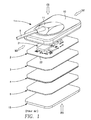
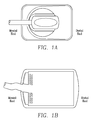
- Figure 1 illustrates a prior art radiological imaging sensor 1 that has a cable side housing 10 connected to a front side housing 15 with a cable 6 running out of cable button connector 11 in front side housing 15 toward mesial side MS of sensor 1.
- an electronics substrate shown generally as 2
- electronic components 21 being mounted on the cable side of electronics substrate 2 (e.g., a ceramic or plastic material)
- an imaging chip shown generally as 3 (preferably a CMOS imaging chip)
- a fiber optic plate shown generally as 4 (which functions as an x-ray filter for improved noise reduction)
- a Csl scintillator shown generally as 5 (optimized for resolution and low noise).
- Sensor 1 has a generally rectangular shape, as illustrated in Figure 1 .
- the shorter sides of the rectangle will always be defined by the direction in which cable 6 exits cable button connector 11.
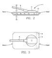
- Mesial side MS (see Figure 1 ) will always be defined as the side toward which cable 6 exits cable button connector 11 while distal side DS will always be defined as the side opposite which cable 6 exits cable button connector 11, even if cable button connector 11 is not centered in cable side housing 10 (see Figure 2 ).
- cable button connector 11 be located more proximate to the distal side DS than centered (see Figure 2 ). The reason such placement is preferred is that it allows more room for cable 6 coming out of cable button connector 11 to twist or turn when the sensor is used in some locations of a patient's mouth, thus reducing stress on the connection between cable 6 and cable button connector 11, which must be watertight.
- electronics substrate 2 has a shock absorption material (not shown) around the periphery of ceramic material 22.
- the space occupied by shock absorption material, as well as space occupied the sensor housing creates a dead space 8 (see Figure 3 ) in which a radiographic image is not obtained, and the size of this dead space will typically be no less than 2 mm.
- a second dead space 9 is created by imaging chip control electronics located on mesial side MS of imaging chip 3 in presently available sensors, which can represent another 4 mm or more of additional dead space.
- dead spaces 8 and 9 in currently available intraoral radiographic sensors is an inability to duplicate the same coverage area in a patient's oral anatomy as x-ray film when placed in the exact same position relative to the patient's teeth.
- This problem is due to the intrinsic design and layout of all digital intraoral sensors, with regard to the placement of the dead space, which is created as a by-product by parts of the electronics on the sensor.
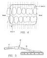
- this 4-8mm dead space is approximately the width of half to a whole canine, or premolar tooth, as shown in Figure 4 .
- Figure 4 illustrates a coverage Area A for a standard premolar bitewing film radiograph. Within Area A, at its mesial side, is another Area B. Area B illustrates a typical loss of imaging area due to dead space for sensor electronics for a digital sensor. Accordingly, Figure 4 illustrates that if a digital dental sensor is placed in the exact position as the x-ray film, the resultant image will not show the first 4-8mm of the mesial end of the patient's anatomy.
- the first prior art solid-state sensors had the cord exiting off the mesial edge. It was along this edge of the associated imaging chip that the control electronics were placed, in close proximity to the cord for efficiency of wiring to the cord. As the cord attachment moved to the back side of the sensor allowing for easier bending of the cable and patient comfort when the sensor was used in a vertical orientation in the patient's mouth, the placement of electronics and resulting imaging dead-space, remained the same. This became part of the industry standard in design and was never questioned because design engineers only thought about ease of fabrication, ease of connection, and minimizing signal loss in the placement of the electronics. No thought was given to clinical ergonomic issues.
- the present invention addresses clinical ergonomic issues, which represents a major change in intraoral sensor design, by moving dead space 9 to distal side DS of imaging chip 3 so that any dead space located on the mesial side of the sensor is kept to a bare minimum attributable solely to shock absorption material and the housing.
- a sensor design is shown in Figure 3 which illustrates a cable side view of an electronics substrate 2 according to the present invention with dead space 9 being located at distal side DS, not mesial side MS.
- cable 6 and cable button connector 11 are shown as trace lines in Figure 3 .
- Locating dead space 9 at distal side DS allows a dental practitioner to capture images not currently obtainable because Area B of Figure 4 , which represents a loss of imaging area due to dead space, is minimized, thus allowing greater capture of teeth located in the mesial area of a radiograph capture, which is especially important when a bitewing or periapical radiograph is being taken of the canine and premolar teeth.
- some of the most painful radiographs captured are the premolar bitewing and posterior periapical views.
- the reason these radiographs are painful to take is that the imaging plate, whether a film or a sensor (which is stiffer and can cause more pain), must be located such that its mesial end is placed as far forward in the patient's mouth as possible to capture the distal aspect of the canine teeth and the mesial aspect of the premolar teeth in a bitewing or periapical view radiograph; and once the patient bites down the edges of the film or sensor dig into the tissue on the anterior ascending aspect of the maxillary palate or the lingual aspect of the anterior mandibular region; thus often causing pain when the mesial aspect of the digital sensor is impinging against these very sensitive anatomic regions during a radiographic exam.
- the sensor When a radiograph is being taken with a sensor with a cord, the sensor must be inserted to that the distal end is located towards the distal aspect of the teeth being imaged and then the mesial end is located at most mesial aspect of the teeth being imaged.
- the procedure for obtaining a radiograph of the patient's posterior teeth is far more comfortable and less painful, and better results are obtained.
- a sensor in accordance with the present invention in which dead space in its mesial end is minimized, represents a significant advance over the prior art and allows dental practitioners to obtain much better radiographs of all teeth being radiographed.
- the present invention is not limited solely to locating dead space 9 at distal side DS and, in alternative embodiments, it is contemplated that, as much as is possible, the imaging chip control electronics for digital sensors should be moved so that they lie within the actual imaging area of imaging chip 3, whether done by sacrifice of active imaging area within individual pixels or by depositing the imaging chip control electronics as a layer upon which the active imaging area is then deposited.
- Figure 6 illustrates an imaging chip 3 which has an imaging chip active area 32 made up of individual pixels 33. Each individual pixel 33 has its own pixel control electronics 34 and active pixel area 35. Imaging chip 3 also has an imaging chip dead space 38 due to chip construction and not due to imaging chip control electronics. In current imaging chips, there is also a dead space 39 (although it is located at mesial side MS, not distal side DS) due to imaging chip control electronics outside of the active pixel area. The imaging chip control electronics can perform many functions, including intra and inter pixel imaging chip control. Thus, in accordance with the alternative embodiments just noted, dead space 39 of Figure 6 can be eliminated, and capture efficiency can be improved, by moving all imaging chip control electronics to a layer that lies underneath the active layer of the imaging chip relative to front side FS.
- imaging chip control electronics layer This can be done by first depositing an imaging chip control electronics layer and then depositing the active imaging area on top of the already deposited electronics layer.
- capture efficiency can be increased by including imaging chip control electronics in each pixel's pixel control electronics 34, even if some active pixel area 35 must be sacrificed.
- connection cable by changing the shape of the connection cable from round or circular to an asymmetric shape that is substantially wider than its height, preferably at least two or more times wider than its height, examples of which might be ovoid or flat.
- a flat cable Such an improved cable, for the remainder of this description, will be referred to as a flat cable.
- a flat cable according to the present invention will be easier to fit to a patient's mouth while certain radiographs are taken because it reduces cord bulk and bite interference. Rather than having to bite down with a circular cord running out between the patient's teeth, the patient will now have to bite down on a flat cord that creates less of a gap between teeth, thus increasing comfort and imaging coverage of the sensor. Also, use of a flat cord may reduce the thickness of cable button connector 11, which should also increase patient comfort and easier placement of the sensor in the patient's mouth.
- a sensor in accordance with the present invention in which a flat cord is implemented represents a significant advance over the prior art and allows dental practitioners to obtain much better radiographs of all teeth being radiographed and increased patient comfort.
- USB connection cables are round and designed to meet applicable standards for USB connections as well as UL and other applicable standards.
- the desire to meet USB standards stems, at least in part, for ease of use and the ability to quickly and easily connect with computers.
- a flat cable suitable for use in the present invention can meet USB standards, but it need not necessarily do so.
- the key design criteria is to reduce the thickness of the flat cable that must fit between upper and lower teeth when certain radiographs are being taken.
- One possible alternative of a flat cable suitable for use in the present invention uses a short flat cable 40, with a length of approximately one meter or less (not shown to scale), that can be connected to a round USB compliant cable 41 by a small connector, an example of which is shown generally in Figure 5 as 42. (Note that connector 42 can be comprised of a female end on one cable and a male end on the other cable).
Landscapes
- Health & Medical Sciences (AREA)
- Life Sciences & Earth Sciences (AREA)
- Medical Informatics (AREA)
- Engineering & Computer Science (AREA)
- Physics & Mathematics (AREA)
- Pathology (AREA)
- Public Health (AREA)
- Biophysics (AREA)
- Nuclear Medicine, Radiotherapy & Molecular Imaging (AREA)
- Optics & Photonics (AREA)
- Veterinary Medicine (AREA)
- Radiology & Medical Imaging (AREA)
- Biomedical Technology (AREA)
- Heart & Thoracic Surgery (AREA)
- Molecular Biology (AREA)
- Surgery (AREA)
- Animal Behavior & Ethology (AREA)
- General Health & Medical Sciences (AREA)
- High Energy & Nuclear Physics (AREA)
- Mathematical Physics (AREA)
- Dentistry (AREA)
- Oral & Maxillofacial Surgery (AREA)
- Apparatus For Radiation Diagnosis (AREA)
Priority Applications (1)
| Application Number | Priority Date | Filing Date | Title |
|---|---|---|---|
| EP14177459.6A EP2801321B1 (de) | 2011-11-18 | 2012-11-16 | Intraorale Röntgenabbildungssensoren mit minimiertem mesialem Abbildungs-Eigenraum |
Applications Claiming Priority (2)
| Application Number | Priority Date | Filing Date | Title |
|---|---|---|---|
| US201161561476P | 2011-11-18 | 2011-11-18 | |
| US13/673,763 US20130129044A1 (en) | 2011-11-18 | 2012-11-09 | Intraoral Radiographic Imaging Sensors with Minimized Mesial Imaging Dead Space |
Related Child Applications (2)
| Application Number | Title | Priority Date | Filing Date |
|---|---|---|---|
| EP14177459.6A Division-Into EP2801321B1 (de) | 2011-11-18 | 2012-11-16 | Intraorale Röntgenabbildungssensoren mit minimiertem mesialem Abbildungs-Eigenraum |
| EP14177459.6A Division EP2801321B1 (de) | 2011-11-18 | 2012-11-16 | Intraorale Röntgenabbildungssensoren mit minimiertem mesialem Abbildungs-Eigenraum |
Publications (3)
| Publication Number | Publication Date |
|---|---|
| EP2594202A2 true EP2594202A2 (de) | 2013-05-22 |
| EP2594202A3 EP2594202A3 (de) | 2013-08-14 |
| EP2594202B1 EP2594202B1 (de) | 2015-01-07 |
Family
ID=47594284
Family Applications (2)
| Application Number | Title | Priority Date | Filing Date |
|---|---|---|---|
| EP12193006.9A Revoked EP2594202B1 (de) | 2011-11-18 | 2012-11-16 | Intraorale Röntgenabbildungssensoren mit minimiertem mesialem Abbildungs-Eigenraum |
| EP14177459.6A Active EP2801321B1 (de) | 2011-11-18 | 2012-11-16 | Intraorale Röntgenabbildungssensoren mit minimiertem mesialem Abbildungs-Eigenraum |
Family Applications After (1)
| Application Number | Title | Priority Date | Filing Date |
|---|---|---|---|
| EP14177459.6A Active EP2801321B1 (de) | 2011-11-18 | 2012-11-16 | Intraorale Röntgenabbildungssensoren mit minimiertem mesialem Abbildungs-Eigenraum |
Country Status (6)
| Country | Link |
|---|---|
| US (1) | US20130129044A1 (de) |
| EP (2) | EP2594202B1 (de) |
| AU (1) | AU2012251928B2 (de) |
| BR (1) | BR102012029310B1 (de) |
| CA (1) | CA2795783C (de) |
| ES (1) | ES2533686T3 (de) |
Cited By (1)
| Publication number | Priority date | Publication date | Assignee | Title |
|---|---|---|---|---|
| EP3556295A4 (de) * | 2016-12-15 | 2020-08-05 | Hamamatsu Photonics K.K. | Intraoraler sensor |
Families Citing this family (7)
| Publication number | Priority date | Publication date | Assignee | Title |
|---|---|---|---|---|
| US20160141318A1 (en) * | 2013-06-28 | 2016-05-19 | Teledyne Dalsa, Inc. | Method and system for assembly of radiological imaging sensor |
| USD782054S1 (en) * | 2014-09-16 | 2017-03-21 | Rayence Co., Ltd. | Interface module for an intraoral sensor |
| USD779068S1 (en) * | 2014-09-16 | 2017-02-14 | Rayence Co., Ltd. | Intraoral sensor |
| DE102015201067B4 (de) | 2015-01-22 | 2022-02-24 | Siemens Healthcare Gmbh | Bestimmung eines Winkels zwischen zwei Teilen eines Knochens |
| CN105662453A (zh) * | 2016-02-29 | 2016-06-15 | 江苏美伦影像系统有限公司 | 一种口腔x射线诊断装置 |
| US10595797B2 (en) * | 2017-01-31 | 2020-03-24 | Teledyne E2V Semiconductors Sas | Dental intraoral radiological image sensor |
| JP6515152B2 (ja) * | 2017-08-30 | 2019-05-15 | 浜松ホトニクス株式会社 | 口腔内センサ、及び口腔内センサの製造方法 |
Citations (1)
| Publication number | Priority date | Publication date | Assignee | Title |
|---|---|---|---|---|
| US7916200B2 (en) | 2005-07-01 | 2011-03-29 | E2V Semiconductors | Image sensor with corner cuts |
Family Cites Families (8)
| Publication number | Priority date | Publication date | Assignee | Title |
|---|---|---|---|---|
| US3851178A (en) * | 1973-03-07 | 1974-11-26 | J Borden | Contour dental x-ray film |
| GB2289983B (en) * | 1994-06-01 | 1996-10-16 | Simage Oy | Imaging devices,systems and methods |
| US5510623A (en) * | 1995-02-24 | 1996-04-23 | Loral Fairchild Corp. | Center readout intra-oral image sensor |
| SE9501332L (sv) * | 1995-04-10 | 1996-10-11 | Regam Medical Systems Ab | Anordning vid CCD-cell |
| US5912942A (en) * | 1997-06-06 | 1999-06-15 | Schick Technologies, Inc. | X-ray detection system using active pixel sensors |
| JP4681774B2 (ja) * | 2001-08-30 | 2011-05-11 | キヤノン株式会社 | 撮像素子、その撮像素子を用いた撮像装置、及びその撮像装置を用いた撮像システム |
| ATE346546T1 (de) * | 2004-08-06 | 2006-12-15 | Gendex Corp | Bild-sensor für zahnmedizinische intraorale röntgenradiographie |
| US7655918B2 (en) * | 2006-07-26 | 2010-02-02 | Fairchild Imaging, Inc | CMOS image sensors adapted for dental applications |
-
2012
- 2012-11-09 US US13/673,763 patent/US20130129044A1/en not_active Abandoned
- 2012-11-14 CA CA2795783A patent/CA2795783C/en active Active
- 2012-11-16 AU AU2012251928A patent/AU2012251928B2/en active Active
- 2012-11-16 EP EP12193006.9A patent/EP2594202B1/de not_active Revoked
- 2012-11-16 BR BR102012029310-2A patent/BR102012029310B1/pt active IP Right Grant
- 2012-11-16 ES ES12193006.9T patent/ES2533686T3/es active Active
- 2012-11-16 EP EP14177459.6A patent/EP2801321B1/de active Active
Patent Citations (1)
| Publication number | Priority date | Publication date | Assignee | Title |
|---|---|---|---|---|
| US7916200B2 (en) | 2005-07-01 | 2011-03-29 | E2V Semiconductors | Image sensor with corner cuts |
Cited By (1)
| Publication number | Priority date | Publication date | Assignee | Title |
|---|---|---|---|---|
| EP3556295A4 (de) * | 2016-12-15 | 2020-08-05 | Hamamatsu Photonics K.K. | Intraoraler sensor |
Also Published As
| Publication number | Publication date |
|---|---|
| CA2795783C (en) | 2019-09-24 |
| EP2594202B1 (de) | 2015-01-07 |
| BR102012029310A2 (pt) | 2014-12-30 |
| BR102012029310B1 (pt) | 2021-05-25 |
| AU2012251928B2 (en) | 2016-04-14 |
| NZ603692A (en) | 2014-12-24 |
| EP2594202A3 (de) | 2013-08-14 |
| ES2533686T3 (es) | 2015-04-14 |
| EP2801321B1 (de) | 2016-08-24 |
| US20130129044A1 (en) | 2013-05-23 |
| EP2801321A2 (de) | 2014-11-12 |
| AU2012251928A1 (en) | 2013-06-06 |
| CA2795783A1 (en) | 2013-05-18 |
| EP2801321A3 (de) | 2014-12-10 |
Similar Documents
| Publication | Publication Date | Title |
|---|---|---|
| CA2795783C (en) | Intraoral radiographic imaging sensors with minimized mesial imaging dead space | |
| US9538967B2 (en) | Intraoral radiographic sensors with cables having increased user comfort and methods of using the same | |
| US7281847B2 (en) | Image sensor for dental intraoral radiography | |
| US9216003B1 (en) | Universal intraoral digital sensor holder for existing digital sensor systems in dentistry | |
| US8450696B2 (en) | Auxiliary component for medical device having additional functionality | |
| KR101499649B1 (ko) | 구강촬영용 트레이, 구강촬영용 트레이를 포함하는 구강촬영장치 및 구강촬영 시스템 | |
| US10130317B2 (en) | Intraoral dental radiological imaging sensor | |
| US8641276B2 (en) | Sealed sensor systems, apparatuses and methods | |
| US20100254518A1 (en) | Digital Radiography Sensors | |
| NZ603692B2 (en) | Intraoral radiographic imaging sensors with minimized mesial imaging dead space | |
| Reddy et al. | Clinical applications of extra-oral periapical radiography | |
| US20220287661A1 (en) | Bite Tray for Alleviating Dental Discomfort | |
| Caiafa | Oral radiology. | |
| KR20230001026U (ko) | 구강카메라용 가이드 헤드 |
Legal Events
| Date | Code | Title | Description |
|---|---|---|---|
| PUAI | Public reference made under article 153(3) epc to a published international application that has entered the european phase |
Free format text: ORIGINAL CODE: 0009012 |
|
| AK | Designated contracting states |
Kind code of ref document: A2 Designated state(s): AL AT BE BG CH CY CZ DE DK EE ES FI FR GB GR HR HU IE IS IT LI LT LU LV MC MK MT NL NO PL PT RO RS SE SI SK SM TR |
|
| AX | Request for extension of the european patent |
Extension state: BA ME |
|
| PUAL | Search report despatched |
Free format text: ORIGINAL CODE: 0009013 |
|
| AK | Designated contracting states |
Kind code of ref document: A3 Designated state(s): AL AT BE BG CH CY CZ DE DK EE ES FI FR GB GR HR HU IE IS IT LI LT LU LV MC MK MT NL NO PL PT RO RS SE SI SK SM TR |
|
| AX | Request for extension of the european patent |
Extension state: BA ME |
|
| RIC1 | Information provided on ipc code assigned before grant |
Ipc: H05K 5/02 20060101ALI20130710BHEP Ipc: H01L 27/146 20060101ALI20130710BHEP Ipc: G01T 1/24 20060101ALI20130710BHEP Free format text: CONFIRMATION OF TERMINATION OF PROCEEDINGS (EPO FORM 1152 DATED 12.06.2013) Ipc: A61B 6/14 20060101AFI20130710BHEP |
|
| 17P | Request for examination filed |
Effective date: 20140212 |
|
| RBV | Designated contracting states (corrected) |
Designated state(s): AL AT BE BG CH CY CZ DE DK EE ES FI FR GB GR HR HU IE IS IT LI LT LU LV MC MK MT NL NO PL PT RO RS SE SI SK SM TR |
|
| GRAP | Despatch of communication of intention to grant a patent |
Free format text: ORIGINAL CODE: EPIDOSNIGR1 |
|
| INTG | Intention to grant announced |
Effective date: 20140704 |
|
| GRAS | Grant fee paid |
Free format text: ORIGINAL CODE: EPIDOSNIGR3 |
|
| GRAA | (expected) grant |
Free format text: ORIGINAL CODE: 0009210 |
|
| AK | Designated contracting states |
Kind code of ref document: B1 Designated state(s): AL AT BE BG CH CY CZ DE DK EE ES FI FR GB GR HR HU IE IS IT LI LT LU LV MC MK MT NL NO PL PT RO RS SE SI SK SM TR |
|
| REG | Reference to a national code |
Ref country code: GB Ref legal event code: FG4D |
|
| REG | Reference to a national code |
Ref country code: CH Ref legal event code: EP |
|
| REG | Reference to a national code |
Ref country code: IE Ref legal event code: FG4D |
|
| REG | Reference to a national code |
Ref country code: AT Ref legal event code: REF Ref document number: 705127 Country of ref document: AT Kind code of ref document: T Effective date: 20150215 |
|
| REG | Reference to a national code |
Ref country code: DE Ref legal event code: R096 Ref document number: 602012004755 Country of ref document: DE Effective date: 20150219 |
|
| REG | Reference to a national code |
Ref country code: NL Ref legal event code: T3 |
|
| REG | Reference to a national code |
Ref country code: ES Ref legal event code: FG2A Ref document number: 2533686 Country of ref document: ES Kind code of ref document: T3 Effective date: 20150414 |
|
| REG | Reference to a national code |
Ref country code: AT Ref legal event code: MK05 Ref document number: 705127 Country of ref document: AT Kind code of ref document: T Effective date: 20150107 |
|
| REG | Reference to a national code |
Ref country code: LT Ref legal event code: MG4D |
|
| PG25 | Lapsed in a contracting state [announced via postgrant information from national office to epo] |
Ref country code: LT Free format text: LAPSE BECAUSE OF FAILURE TO SUBMIT A TRANSLATION OF THE DESCRIPTION OR TO PAY THE FEE WITHIN THE PRESCRIBED TIME-LIMIT Effective date: 20150107 Ref country code: HR Free format text: LAPSE BECAUSE OF FAILURE TO SUBMIT A TRANSLATION OF THE DESCRIPTION OR TO PAY THE FEE WITHIN THE PRESCRIBED TIME-LIMIT Effective date: 20150107 Ref country code: SE Free format text: LAPSE BECAUSE OF FAILURE TO SUBMIT A TRANSLATION OF THE DESCRIPTION OR TO PAY THE FEE WITHIN THE PRESCRIBED TIME-LIMIT Effective date: 20150107 Ref country code: BG Free format text: LAPSE BECAUSE OF FAILURE TO SUBMIT A TRANSLATION OF THE DESCRIPTION OR TO PAY THE FEE WITHIN THE PRESCRIBED TIME-LIMIT Effective date: 20150407 Ref country code: NO Free format text: LAPSE BECAUSE OF FAILURE TO SUBMIT A TRANSLATION OF THE DESCRIPTION OR TO PAY THE FEE WITHIN THE PRESCRIBED TIME-LIMIT Effective date: 20150407 |
|
| PG25 | Lapsed in a contracting state [announced via postgrant information from national office to epo] |
Ref country code: PL Free format text: LAPSE BECAUSE OF FAILURE TO SUBMIT A TRANSLATION OF THE DESCRIPTION OR TO PAY THE FEE WITHIN THE PRESCRIBED TIME-LIMIT Effective date: 20150107 Ref country code: GR Free format text: LAPSE BECAUSE OF FAILURE TO SUBMIT A TRANSLATION OF THE DESCRIPTION OR TO PAY THE FEE WITHIN THE PRESCRIBED TIME-LIMIT Effective date: 20150408 Ref country code: LV Free format text: LAPSE BECAUSE OF FAILURE TO SUBMIT A TRANSLATION OF THE DESCRIPTION OR TO PAY THE FEE WITHIN THE PRESCRIBED TIME-LIMIT Effective date: 20150107 Ref country code: IS Free format text: LAPSE BECAUSE OF FAILURE TO SUBMIT A TRANSLATION OF THE DESCRIPTION OR TO PAY THE FEE WITHIN THE PRESCRIBED TIME-LIMIT Effective date: 20150507 Ref country code: AT Free format text: LAPSE BECAUSE OF FAILURE TO SUBMIT A TRANSLATION OF THE DESCRIPTION OR TO PAY THE FEE WITHIN THE PRESCRIBED TIME-LIMIT Effective date: 20150107 Ref country code: RS Free format text: LAPSE BECAUSE OF FAILURE TO SUBMIT A TRANSLATION OF THE DESCRIPTION OR TO PAY THE FEE WITHIN THE PRESCRIBED TIME-LIMIT Effective date: 20150107 |
|
| REG | Reference to a national code |
Ref country code: DE Ref legal event code: R026 Ref document number: 602012004755 Country of ref document: DE |
|
| PLBI | Opposition filed |
Free format text: ORIGINAL CODE: 0009260 |
|
| PG25 | Lapsed in a contracting state [announced via postgrant information from national office to epo] |
Ref country code: SK Free format text: LAPSE BECAUSE OF FAILURE TO SUBMIT A TRANSLATION OF THE DESCRIPTION OR TO PAY THE FEE WITHIN THE PRESCRIBED TIME-LIMIT Effective date: 20150107 Ref country code: EE Free format text: LAPSE BECAUSE OF FAILURE TO SUBMIT A TRANSLATION OF THE DESCRIPTION OR TO PAY THE FEE WITHIN THE PRESCRIBED TIME-LIMIT Effective date: 20150107 Ref country code: RO Free format text: LAPSE BECAUSE OF FAILURE TO SUBMIT A TRANSLATION OF THE DESCRIPTION OR TO PAY THE FEE WITHIN THE PRESCRIBED TIME-LIMIT Effective date: 20150107 Ref country code: CZ Free format text: LAPSE BECAUSE OF FAILURE TO SUBMIT A TRANSLATION OF THE DESCRIPTION OR TO PAY THE FEE WITHIN THE PRESCRIBED TIME-LIMIT Effective date: 20150107 Ref country code: DK Free format text: LAPSE BECAUSE OF FAILURE TO SUBMIT A TRANSLATION OF THE DESCRIPTION OR TO PAY THE FEE WITHIN THE PRESCRIBED TIME-LIMIT Effective date: 20150107 |
|
| PLAX | Notice of opposition and request to file observation + time limit sent |
Free format text: ORIGINAL CODE: EPIDOSNOBS2 |
|
| 26 | Opposition filed |
Opponent name: SIRONA DENTAL SYSTEMS GMBH Effective date: 20151007 |
|
| REG | Reference to a national code |
Ref country code: FR Ref legal event code: PLFP Year of fee payment: 4 |
|
| PGFP | Annual fee paid to national office [announced via postgrant information from national office to epo] |
Ref country code: IT Payment date: 20151130 Year of fee payment: 4 Ref country code: FI Payment date: 20151120 Year of fee payment: 4 |
|
| PG25 | Lapsed in a contracting state [announced via postgrant information from national office to epo] |
Ref country code: SI Free format text: LAPSE BECAUSE OF FAILURE TO SUBMIT A TRANSLATION OF THE DESCRIPTION OR TO PAY THE FEE WITHIN THE PRESCRIBED TIME-LIMIT Effective date: 20150107 |
|
| PGFP | Annual fee paid to national office [announced via postgrant information from national office to epo] |
Ref country code: ES Payment date: 20151124 Year of fee payment: 4 Ref country code: NL Payment date: 20151124 Year of fee payment: 4 Ref country code: FR Payment date: 20151124 Year of fee payment: 4 |
|
| PLAF | Information modified related to communication of a notice of opposition and request to file observations + time limit |
Free format text: ORIGINAL CODE: EPIDOSCOBS2 |
|
| PG25 | Lapsed in a contracting state [announced via postgrant information from national office to epo] |
Ref country code: BE Free format text: LAPSE BECAUSE OF FAILURE TO SUBMIT A TRANSLATION OF THE DESCRIPTION OR TO PAY THE FEE WITHIN THE PRESCRIBED TIME-LIMIT Effective date: 20150107 |
|
| REG | Reference to a national code |
Ref country code: DE Ref legal event code: R119 Ref document number: 602012004755 Country of ref document: DE |
|
| PG25 | Lapsed in a contracting state [announced via postgrant information from national office to epo] |
Ref country code: LU Free format text: LAPSE BECAUSE OF FAILURE TO SUBMIT A TRANSLATION OF THE DESCRIPTION OR TO PAY THE FEE WITHIN THE PRESCRIBED TIME-LIMIT Effective date: 20151116 Ref country code: MC Free format text: LAPSE BECAUSE OF FAILURE TO SUBMIT A TRANSLATION OF THE DESCRIPTION OR TO PAY THE FEE WITHIN THE PRESCRIBED TIME-LIMIT Effective date: 20150107 |
|
| REG | Reference to a national code |
Ref country code: CH Ref legal event code: PL |
|
| PG25 | Lapsed in a contracting state [announced via postgrant information from national office to epo] |
Ref country code: CH Free format text: LAPSE BECAUSE OF NON-PAYMENT OF DUE FEES Effective date: 20151130 Ref country code: LI Free format text: LAPSE BECAUSE OF NON-PAYMENT OF DUE FEES Effective date: 20151130 |
|
| REG | Reference to a national code |
Ref country code: IE Ref legal event code: MM4A |
|
| PG25 | Lapsed in a contracting state [announced via postgrant information from national office to epo] |
Ref country code: IE Free format text: LAPSE BECAUSE OF NON-PAYMENT OF DUE FEES Effective date: 20151116 Ref country code: DE Free format text: LAPSE BECAUSE OF NON-PAYMENT OF DUE FEES Effective date: 20160601 |
|
| RDAF | Communication despatched that patent is revoked |
Free format text: ORIGINAL CODE: EPIDOSNREV1 |
|
| STAA | Information on the status of an ep patent application or granted ep patent |
Free format text: STATUS: THE PATENT HAS BEEN GRANTED |
|
| REG | Reference to a national code |
Ref country code: DE Ref legal event code: R064 Ref document number: 602012004755 Country of ref document: DE Ref country code: DE Ref legal event code: R103 Ref document number: 602012004755 Country of ref document: DE |
|
| RDAG | Patent revoked |
Free format text: ORIGINAL CODE: 0009271 |
|
| 27W | Patent revoked |
Effective date: 20161121 |
|
| GBPR | Gb: patent revoked under art. 102 of the ep convention designating the uk as contracting state |
Effective date: 20161121 |
|
| PG25 | Lapsed in a contracting state [announced via postgrant information from national office to epo] |
Ref country code: HU Free format text: LAPSE BECAUSE OF FAILURE TO SUBMIT A TRANSLATION OF THE DESCRIPTION OR TO PAY THE FEE WITHIN THE PRESCRIBED TIME-LIMIT; INVALID AB INITIO Effective date: 20121116 |
|
| PG25 | Lapsed in a contracting state [announced via postgrant information from national office to epo] |
Ref country code: MT Free format text: LAPSE BECAUSE OF NON-PAYMENT OF DUE FEES Effective date: 20151116 |
|
| PG25 | Lapsed in a contracting state [announced via postgrant information from national office to epo] |
Ref country code: AL Free format text: LAPSE BECAUSE OF FAILURE TO SUBMIT A TRANSLATION OF THE DESCRIPTION OR TO PAY THE FEE WITHIN THE PRESCRIBED TIME-LIMIT Effective date: 20150107 |
|
| STAA | Information on the status of an ep patent application or granted ep patent |
Free format text: STATUS: PATENT REVOKED |
|
| PG25 | Lapsed in a contracting state [announced via postgrant information from national office to epo] |
Ref country code: CY Free format text: LAPSE BECAUSE OF FAILURE TO SUBMIT A TRANSLATION OF THE DESCRIPTION OR TO PAY THE FEE WITHIN THE PRESCRIBED TIME-LIMIT Effective date: 20150107 Ref country code: PT Free format text: LAPSE BECAUSE OF FAILURE TO SUBMIT A TRANSLATION OF THE DESCRIPTION OR TO PAY THE FEE WITHIN THE PRESCRIBED TIME-LIMIT Effective date: 20150107 |
|
| PG25 | Lapsed in a contracting state [announced via postgrant information from national office to epo] |
Ref country code: TR Free format text: LAPSE BECAUSE OF FAILURE TO SUBMIT A TRANSLATION OF THE DESCRIPTION OR TO PAY THE FEE WITHIN THE PRESCRIBED TIME-LIMIT Effective date: 20150107 |