EP2594227A2 - Dispositif de prise d'empreinte et procédé de détection tridimensionnelle de structures intra-buccales ainsi qu'un dispositif de scanner correspondant - Google Patents
Dispositif de prise d'empreinte et procédé de détection tridimensionnelle de structures intra-buccales ainsi qu'un dispositif de scanner correspondant Download PDFInfo
- Publication number
- EP2594227A2 EP2594227A2 EP20120192519 EP12192519A EP2594227A2 EP 2594227 A2 EP2594227 A2 EP 2594227A2 EP 20120192519 EP20120192519 EP 20120192519 EP 12192519 A EP12192519 A EP 12192519A EP 2594227 A2 EP2594227 A2 EP 2594227A2
- Authority
- EP
- European Patent Office
- Prior art keywords
- impression
- tooth
- marker
- scanning
- impression device
- Prior art date
- Legal status (The legal status is an assumption and is not a legal conclusion. Google has not performed a legal analysis and makes no representation as to the accuracy of the status listed.)
- Withdrawn
Links
Images




Classifications
-
- A—HUMAN NECESSITIES
- A61—MEDICAL OR VETERINARY SCIENCE; HYGIENE
- A61C—DENTISTRY; APPARATUS OR METHODS FOR ORAL OR DENTAL HYGIENE
- A61C9/00—Impression cups, i.e. impression trays; Impression methods
- A61C9/004—Means or methods for taking digitized impressions
- A61C9/0046—Data acquisition means or methods
-
- A—HUMAN NECESSITIES
- A61—MEDICAL OR VETERINARY SCIENCE; HYGIENE
- A61B—DIAGNOSIS; SURGERY; IDENTIFICATION
- A61B6/00—Apparatus or devices for radiation diagnosis; Apparatus or devices for radiation diagnosis combined with radiation therapy equipment
- A61B6/50—Apparatus or devices for radiation diagnosis; Apparatus or devices for radiation diagnosis combined with radiation therapy equipment specially adapted for specific body parts; specially adapted for specific clinical applications
- A61B6/51—Apparatus or devices for radiation diagnosis; Apparatus or devices for radiation diagnosis combined with radiation therapy equipment specially adapted for specific body parts; specially adapted for specific clinical applications for dentistry
-
- A—HUMAN NECESSITIES
- A61—MEDICAL OR VETERINARY SCIENCE; HYGIENE
- A61B—DIAGNOSIS; SURGERY; IDENTIFICATION
- A61B6/00—Apparatus or devices for radiation diagnosis; Apparatus or devices for radiation diagnosis combined with radiation therapy equipment
- A61B6/50—Apparatus or devices for radiation diagnosis; Apparatus or devices for radiation diagnosis combined with radiation therapy equipment specially adapted for specific body parts; specially adapted for specific clinical applications
- A61B6/51—Apparatus or devices for radiation diagnosis; Apparatus or devices for radiation diagnosis combined with radiation therapy equipment specially adapted for specific body parts; specially adapted for specific clinical applications for dentistry
- A61B6/512—Intraoral means
-
- A—HUMAN NECESSITIES
- A61—MEDICAL OR VETERINARY SCIENCE; HYGIENE
- A61C—DENTISTRY; APPARATUS OR METHODS FOR ORAL OR DENTAL HYGIENE
- A61C9/00—Impression cups, i.e. impression trays; Impression methods
-
- A—HUMAN NECESSITIES
- A61—MEDICAL OR VETERINARY SCIENCE; HYGIENE
- A61C—DENTISTRY; APPARATUS OR METHODS FOR ORAL OR DENTAL HYGIENE
- A61C9/00—Impression cups, i.e. impression trays; Impression methods
- A61C9/0006—Impression trays
-
- A—HUMAN NECESSITIES
- A61—MEDICAL OR VETERINARY SCIENCE; HYGIENE
- A61C—DENTISTRY; APPARATUS OR METHODS FOR ORAL OR DENTAL HYGIENE
- A61C9/00—Impression cups, i.e. impression trays; Impression methods
- A61C9/004—Means or methods for taking digitized impressions
Definitions
- the invention relates to an impression device and a method for the three-dimensional detection of intraoral structures, in particular of teeth and ground tooth stumps, as well as a corresponding scanning device.
- impression materials In the analogue impression of teeth and soft tissue different impression materials can be used.
- rigid impression materials impression plaster, zinc oxide-eugenol pastes, plastic impression compounds
- reversibly rigid impression materials impression waxes, gutta-percha, composition impression materials
- elastic impression compounds The latter are in turn subdivided into irreversibly elastic impression materials (alginates, polysulfides, polyethers, silicones) and reversibly elastic impression materials such as hydrocolloids.
- both the individual stumps and the entire jaw are captured in a joint molding process. If the preparations of the teeth are subgingival, the gingival margin must be extended by appropriate measures, such as by means of retraction threads, so that the impression material can also penetrate into these areas.
- a classical analogue impression is made in a first step, which is not poured out with plaster in a subsequent step, but digitized with the aid of a laboratory scanner.
- laboratory scanners often work on a light-optical basis, using laser light-section methods, Strip light projection or conoscopic holography.
- all light-optical systems have the disadvantage that undercut areas in the impression can not be detected.
- Analogous impression methods also have the disadvantage that they occasionally cause a gag reflex during taking the impression or a feeling of helplessness in the patient. In addition, the unpleasant taste of the impression material is often criticized.
- the US 3,304,608 A describes a two-part molded impression sleeve, wherein a first, closed on one side and filled with an impression material sleeve for generating the impression of a prepared tooth in a second, already slipped over the tooth to be molded, hollow cylindrical and open on both sides sleeve is inserted, wherein the inner diameter of the second Sleeve substantially corresponds to the outer diameter of the first sleeve.
- the second sleeve has at its distal end through openings over which excess impression material can escape.
- the DE 10 2009 044 147 A1 further describes a method for creating a digital data model for at least a portion of an upper jaw, wherein at least one digital maxillary data model is generated by scanning at least a portion of the maxilla or an upper jaw model or at least a portion of an impression of the upper jaw model or upper jaw model by means of a scanning device.
- the method provides that additionally at least one impression of one tooth or of a plurality of teeth of the upper jaw in a face bow registration of a dental sheet is scanned in its relative position to a coordinate system assigned to the face sheet by means of the scanning device and a digital impression data model is generated therefrom.
- the location of the digital maxillary data model in the facebow assigned coordinate system by comparison of the digital maxillary data model with the digital impression data model set.
- the impression device has a molding element which can be placed on a tooth or a tooth stump in order to take an impression of the tooth or of the tooth stump.
- the impression element comprises at least one marker which is arranged on the impression element such that the position and the orientation of the impression element placed on the tooth or tooth stump can be determined in an intraoral scan.
- the impression device has at least one referencing marker.
- it can be connected to at least one referencing marker. The referencing marker is in each case arranged so that it can be scanned together with the impression in an extra-oral scan.
- a two-step scanning process is provided.
- the oral cavity including the impression device, is scanned in the case of an impression device placed on the tooth or tooth stump.
- the marker of the impression device is scanned, which is arranged in a known position relative to the impression device.
- the result of the intraoral scan is a first set of data containing 3D information of most of the oral cavity and the position and orientation of the oral cavity impression device, but not of the structures covered by the impression device.
- these structures are just recorded analogously by the impression.
- all the 3D information has already been recorded, but it is not yet fully digital.
- the missing digital information is obtained in a second step with the help of an extraoral scan of the impression.
- the data record obtained contains exactly that 3D information that is missing in the first data record.
- the referencing marker can either be part of the impression device or can be connected to the impression device.
- the referencing marker is attached to an outer side of the impression device in such a way that it can be detected on the one hand in the extraoral scan, but on the other hand is not covered in the intraoral scan of essential areas of the oral cavity which are detected during the intraoral scan should.
- the referencing marker is part of the extraoral scanning device, wherein the referencing marker is in turn arranged on the extraoral Einscanvoriques that it can be scanned together with the impression in the extraoral Einscanvortechnisch.
- the impression element itself does not have to have a referencing marker, which is detected in the extraoral scan.
- the referencing marker is "connectable" to the impression device, namely via the extraoral scan-in device. In this broad sense is present in the Revelation to understand the term "connectable”.
- it is essential that the impression element for the extraoral scan is positioned exactly in the extraoral scanning device, but at least exactly with respect to the referencing marker.
- the positioning means described in greater detail below for spatially exact positioning of the impression element with respect to the extraoral scanning device have been found to be particularly useful.
- embodiments in which the referencing marker is part of the impression device have the advantage that the spatial arrangement of the referencing marker with respect to the impression device is predetermined with the utmost precision
- embodiments in which the referencing marker is provided on the extraoral scanning device have the advantage of that the referencing marker can be omitted on the impression device, as a result of which the impression device is technically simpler and thus less expensive to produce.
- a referencing marker which is arranged directly on the impression element, there is the risk that the referencing marker will cover essential areas of the oral cavity during the intraoral scan and thus make it unscanable. This problem can be avoided in the case of a referencing marker, which is not permanently connected to the impression device but merely "connectable" for the purpose of the extraoral scan.
- An essential basic idea of the invention is therefore to provide a marker and a referencing marker for the registration of two data sets, each of which has a known relationship to a casting element, which is detected both in an intra-oral scan and in an extra-oral scan, so that via the known relationship the marker or the Referenzierungsmarkers to the impression device, the registration of the record, which is obtained in the Intraoralscan, with the record that is obtained in the Extraoralscan possible. Consequently, according to the invention, the arrangement of the marker or of the referencing marker with respect to the impression device should not be limited to the examples described herein.
- An embodiment of the invention has as a shaping element a sleeve for receiving an impression material.
- the sleeve has an open and a closed end, wherein the marker is arranged at the closed end.
- the marker may be formed, for example, at least partially spherical.
- the marker may have at least one lateral flattening which, depending on the embodiment, is at least partially planar.
- the marker has at least two flattenings, which are arranged at least in sections in planes lying perpendicular to one another.
- a particularly effective marker is therefore at least partially spherical and comprises at least two flat flat portions, which are arranged at least in sections in planes lying perpendicular to each other.
- the marker is at least partially pyramid-shaped.
- the pyramid-shaped portion of the marker may be based on a pyramid with a triangular base, with a square base, or with a rectangular base.
- the marker has at least one spherical element.
- the marker has four hemispherical elements, which are preferably arranged in a common plane at the vertices of a square or a rectangle.
- a further embodiment of the invention provides that the marker has at least two balls arranged one above the other, at least one of the balls having at least one flattening. Particularly preferably, each of the balls on at least two flats, wherein each ball two flats are at least partially planar and aligned perpendicular to each other.
- the marker is connected via a connecting element with the impression sleeve, wherein the connecting element extends from the closed end of the impression sleeve.
- the connecting element has a connecting surface, via which the at least one marker is in contact with the connecting element.
- the connecting surface may extend parallel to the closed end of the impression sleeve.
- the connecting element has a further function, according to which it has or forms positioning means for spatially exact positioning of the impression device in an extra-oral scanning device or in a holder thereof.
- the positioning means are in no way limited within the scope of the invention.
- the positioning means has at least one groove or a spring of a tongue and groove connection.
- a form-fitting dovetail connection is formed between the extraoral scanning device or the holder and the impression device via the connecting element with the aid of the positioning means for spatially exact positioning.
- the marker also comprises (or comprises) a positioning means for the spatially exact positioning of the impression device in an extraoral scanning device.
- This means may be, for example, a guide groove which is formed on an end remote from the impression sleeve of the marker.
- the guide groove of the marker may be engaged with a guide rib of the extraoral scanning device upon insertion of the impression element into an extra-oral scanning device.
- the axis of symmetry of the guide groove is parallel to the axis of symmetry of the tongue and groove joint, if provided aligned.
- the means for the spatially exact positioning of the impression device in the extraoral Einscanvoroplasty are formed in such a counterpart, that whenever the impression device or the extra-oral Einscanvoroplasty has a first means for the spatially exact positioning of the impression device, each other assembly a means complementary to the first means should have, so that the spatially exact positioning of the impression device is achieved in an extraoral Einscanvoroplasty by their interaction.
- cooperating means the already mentioned tongue and groove connection, in which one of the two modules (ie impression device or extra-oral Einscanvortechnisch) has the groove and the other the spring.
- the extraoral Einscanvorraum or the holder either a guide rib or a guide groove has, which is engageable with the respective other assembly, which is formed at the end remote from the impression sleeve of the marker, in engagement.
- the impression device can be inserted into a scanning device according to one of the embodiments described above, wherein the spatially exact arrangement of the impression device, in particular with respect to the referencing marker of the scanning device pay attention.
- the method according to the invention following the above-mentioned steps, to combine the first and the second data set with reference to them a known spatial relationship between the at least one marker of the impression device and the referencing marker.
- the tooth or stump is scanned directly by intraoral scan.
- an analogous impression of the tooth or stump of the tooth is additionally taken in the manner described above, which is then scanned in the above-mentioned step E.), whereby a second data set is produced which bypasses the subgingival structures via the analogue Imprint recorded.
- the two data sets are registered by the fact that according to step F.) Section of the digital image of the tooth or the tooth stump in the first record with a portion of the digital image of the analog impression in the second record is brought into line.
- the so-called “best-fit alignment” is suitable.
- the best-fit alignment is a well-established method for matching images. Roughly speaking, this is a minimization method in which the sum of the distances between corresponding points on the objects to be covered is minimized.
- the merging of the first and the second data set comprises a best-fit alignment.
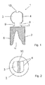
- FIG. 1 a first embodiment of the impression device 1 according to the invention is shown, with a molded as a molding sleeve 2 impression element, which is filled with an impression material 8.
- the impression sleeve 2 has an open and a closed end and a marker 3, which is connected via a connecting element 7 with the impression sleeve 2, wherein the connecting element 7 extends from the closed end of the impression sleeve 2.
- an imprint 30 shown in the impression compound 8 can be seen.
- the marker 3 is at least partially spherical and has at least one recognizable flattening 4 in the illustrated cross-sectional view.
- the connecting element 7 has means 9 for spatially exact positioning of the impression device 1 in an extra-oral scanning device 20 according to FIGS Figures 9 and 10 on.
- the positioning means 9 are formed as grooves of a dovetail joint and have a longitudinal axis which is aligned perpendicular to the plane of the drawing.
- the grooves 9 may be provided with corresponding springs forming part of an extra-oral scanning device 20 (see Figures 9 and 10 ) or a holder thereof are engaged, whereby a tongue and groove connection for spatially exact positioning of the impression device 1 in the extraoral Einscanvorraum 20 is formed.
- the illustrated embodiment does not have a referencing flag, so it must be provided by an extra-oral scanning device 20. Due to the known position and orientation of the marker 3 with respect to the impression sleeve 2, the exact position and orientation of the impression element 1 in the oral cavity can be determined from the first data set obtained during the intraoral scan. In the extraoral scan, the shape and the position and orientation of the molded tooth or tooth stump with respect to the impression device 1 are also determined from the second data set obtained thereby, including the referencing marker. Finally, after registration of both sets of data in addition to the exact shape of the tooth or tooth stump including the subgingival structures and its exact position and orientation within the oral cavity can be determined. The flattening 4 on the otherwise spherical marker 3 can in particular serve to determine the orientation of the tooth or the tooth stump.
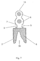
- the further means for spatially exact positioning of the impression device 1 in an extraoral scanning device 20 can be seen more clearly, which in the present case is a guide groove 10 which is formed on an end of the marker 3 remote from the impression sleeve 2.
- FIGS. 3 and 4 illustrated embodiment of an impression device 1 according to the invention differs from that in the Figures 1 and 2 shown by the fact that the
- Marker 3 is designed in the form of a pyramid with a square base. This is in turn connected via a connecting element 7 with the impression sleeve 2, wherein the connecting element 7 extends from the closed end of the impression sleeve 2 and according to the above-described embodiment comprises the positioning means 9.
- FIGS. 5 and 6 shown embodiment of an impression device 1 according to the invention has as a marker 3 four hemispherical elements 5, which are arranged at the vertices of a square.
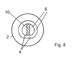
- the marker 3 of the embodiment according to the FIGS. 7 and 8th comprises two superimposed balls 6, each of the balls 6 has exactly one flat 4, which are arranged parallel to each other.
- the stacked balls 6 of the marker 3 are in turn connected via a connecting element 7, which adjoins the lower ball 6, with the closed end of the impression sleeve 2.
- the connecting element 7 again comprises means 9 for spatially exact positioning of the impression device 1 in an extraoral scanning device 20 according to FIGS Figures 9 and 10 wherein the positioning means 9 are formed as grooves of a dovetail joint.
- the marker 3 comprises a further means for spatially exact positioning, which is designed as a guide groove 10, which is formed on the side remote from the impression sleeve 2 end of the marker 3 and with a guide rib 23 (see FIGS. 9 and 10 ) provided by the extraoral scanning device 20 and a holder thereof, respectively.
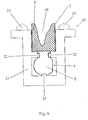
- FIG. 9 and 10 is a cross-sectional view and a plan view of an extra-oral Einscanvoroplasty invention 20 shown, in which an impression device 1 according to the embodiment of the Figures 1 and 2 is inserted.
- the extraoral scanning device 20 comprises a holder 21 in which the impression device 1 is accommodated.
- the holder 21, like the impression device 1, comprises means 22 for the spatially exact positioning of the impression device 1 with respect to the holder 21 and a referencing marker 24.
- the positioning means 9 (see also FIG FIG. 1 ) of the impression device 1 with the means 22 of the holder 21 for the spatially exact positioning of the impression device 1 together. They form a dovetail joint.
- the holder 21 comprises a guide rib 23, which in a guide groove 10 (see also FIG. 1 ), which on the side facing away from the impression sleeve 2 End of the marker is formed, engages.
- the referencing markers 24 are arranged on a U-shaped referencing ring 25.
- the longitudinal axes of the means 22, the positioning means 9, the guide groove 10 and the guide rib 23 are aligned in parallel. This makes it possible for the impression device 1 for the spatially exact positioning in the scanning device 20 to be inserted linearly into the scanning device 20 or the holder 21. Apart from the degree of freedom in the direction of insertion, the position of the impression device 1 in the scanning device 20 is thus already predetermined by the means described above. The exact position in the direction of insertion can be specified by a stop, a locking position or similar means.
- Referenzianssmarkers 24 After scanning both the removed impression and the provided at the Einscanvorraum 20 Referenz michsmarkers 24 due to the known arrangement of Referenz michsmarker 24 and impression device 1 to each other and using the information obtained from the Intraoralscan information about the position of the impression device 1 during the impression in the oral cavity precise position, alignment and geometry of the molded tooth or tooth stump are determined in the oral cavity.
- referencing marker 24 it is not necessary for the referencing marker 24 to be provided on the scanning device 20. Instead, it is also possible to provide a referencing marker directly on the impression device 1 which is capable of being detected in the extra-oral scan. Examples of this are in Fig. 11 . 12 and 13 shown.
- Fig. 11 shows a sectional view of an impression device 1, which is basically constructed similar to those of the embodiments described above.
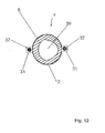
- this impression device 1 contains a marker arrangement 31, which carries a spherical referencing marker 32 in the embodiment shown. Since the referencing marker 32 is characterized by its three-dimensional shape, it is also referred to as a "geometric marker". The referencing marker 32 is arranged so that it can be well detected in the extra-oral scan of the impression 30 in the impression compound 8.
- Fig. 12 clearly, which is a top view of the figure of Fig. 11 shows, ie a look in the impression 30 in the sleeve 2 inside. How out Fig. 12 can be seen, the marker assembly 31 with the Referenzianssmarker 32 is clearly visible in this view.
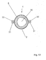
- Fig. 13 shows an alternative embodiment in which the marker assembly 31 is not a geometric, but a so-called “optical marker” 33 shows.
- An "optical” marker is not characterized by a specific geometry or three-dimensional shape, but by a specific optical representation, in the illustrated embodiment, a dark ring on a bright circle. Referencing markers 32 and 33 are merely exemplary.
- the impression sleeve according to the invention has a characteristic geometry. It comprises, for example, a substantially hollow cylindrical structure, wherein the base surface is preferably circular or oval. Ideally, the footprint is selected according to the cross-sections of the different types of tooth root.
- the reference cross-section should be the horizontal section through the respective tooth type at the height of the transition of the tooth root to the tooth crown. Likewise, different sizes and lengths of sleeves may be suitable for each type of tooth.
- the geometry of the marker is to be selected in particular according to the fact that it can be detected with the help of common intraoral scanner as geometrically as possible.
- the impression sleeve is filled with impression material and then placed on the prepared tooth or tooth stump. Any laterally overflowing material can be removed.
- Thedesformenden teeth or tooth stumps can each be molded individually or simultaneously.
- the impression sleeves remain in situ for intraoral scanning.
- the digital 3D capture using intraoral scanner. All structures required for further processing are recorded, in particular teeth, the gingiva, prepared stumps and opposing teeth. The detection of subgingival areas of the prepared teeth or stumps is not possible here. However, these were previously recorded via the analog print. The scannable impression sleeve with its marker will also be digitized in this step.
- the impression device For extra-oral scanning with the aid of the extra-oral scanning device, after the impression material has cured, the impression device is pulled by the prepared tooth or tooth stump. Subsequently, the impression device is positioned in the extraoral scanning device. This can be done for example by lateral insertion, in which between the means for the spatially exact positioning of the impression device in the extraoral Einscanvorplatz both the impression device and the extraoral Einscanvorides a tongue and groove connection between the modules is made.
- This can be configured, for example, as a dovetail joint or as a prismatic guide.
- such connections between the impression device and the extraoral Einscanvoroplasty or a holder thereof are formed on opposite sides of the connecting element of the impression device. In this way, the impression device can be connected by insertion into the extraoral Einscanvorides with this.
- the end position can be determined in the direction of insertion, for example by means of a stop.
- the tooth or tooth stump impression in the impression sleeve is preferably scanned in a light-optical manner, which takes place either with the aid of a separate scanner or with the aid of the digital 3D intraoral scanner already used for the interoral scanning process.
- the exact position of the tooth stump molded with the impression device can be determined in the overall image of the jaw which has been detected with the aid of the intraoral scanner.
- the result is a digital intraoral imprint, which in addition to a scan of the entire jaw, also has scan data for subgingival dissection.
- the marker 3 of the impression device 1 and the referencing markers 24, 32 or 33 can be dispensed with.
- the intraoral scan of the oral cavity without impression device 1 is taken to produce a first data set comprising a digital image of the oral cavity.
- an impression device 1 is placed on a tooth or a tooth stump within the oral cavity, wherein an impression 30 of the tooth or tooth stump is made in the impression material 8.
- the impression device 1 can basically be of one of the types described above, with the exception that it does not require a marker 3.
- the analog impression 30 in the impression device 1 is then extraorally scanned to obtain a second data set.
- This second data set contains no referencing markers 24, 32 or 33, unlike the embodiment described above. However, as before, this second data set contains all the information from the analog print 30, i. also the subgingival structures, which are not shown in the first data set for the reasons described above.
- the first and second data sets are registered by matching a portion of the digital image of the tooth or tooth stump in the first data set with a portion of the digital image of the analog impression in the second data set, for example by means of a Best -Fit alignments.
- a peculiarity of the invention in both embodiments described thus consists in the combination of analog and digital impression techniques, wherein the respective disadvantages are avoided and the respective advantages of both impression techniques are made usable.
Landscapes
- Health & Medical Sciences (AREA)
- Life Sciences & Earth Sciences (AREA)
- Oral & Maxillofacial Surgery (AREA)
- Dentistry (AREA)
- Animal Behavior & Ethology (AREA)
- General Health & Medical Sciences (AREA)
- Public Health (AREA)
- Veterinary Medicine (AREA)
- Epidemiology (AREA)
- Engineering & Computer Science (AREA)
- Medical Informatics (AREA)
- Pathology (AREA)
- High Energy & Nuclear Physics (AREA)
- Biophysics (AREA)
- Nuclear Medicine, Radiotherapy & Molecular Imaging (AREA)
- Optics & Photonics (AREA)
- Physics & Mathematics (AREA)
- Radiology & Medical Imaging (AREA)
- Biomedical Technology (AREA)
- Heart & Thoracic Surgery (AREA)
- Molecular Biology (AREA)
- Surgery (AREA)
- Dental Tools And Instruments Or Auxiliary Dental Instruments (AREA)
Applications Claiming Priority (1)
| Application Number | Priority Date | Filing Date | Title |
|---|---|---|---|
| DE102011055356A DE102011055356A1 (de) | 2011-11-15 | 2011-11-15 | Abformvorrichtung und Verfahren zur dreidimensionalen Erfassung von intraoralen Strukturen sowie eine entsprechende Einscanvorrichtung |
Publications (2)
| Publication Number | Publication Date |
|---|---|
| EP2594227A2 true EP2594227A2 (fr) | 2013-05-22 |
| EP2594227A3 EP2594227A3 (fr) | 2015-04-08 |
Family
ID=47221161
Family Applications (1)
| Application Number | Title | Priority Date | Filing Date |
|---|---|---|---|
| EP20120192519 Withdrawn EP2594227A3 (fr) | 2011-11-15 | 2012-11-14 | Dispositif de prise d'empreinte et procédé de détection tridimensionnelle de structures intra-buccales ainsi qu'un dispositif de scanner correspondant |
Country Status (3)
| Country | Link |
|---|---|
| US (2) | US20130122454A1 (fr) |
| EP (1) | EP2594227A3 (fr) |
| DE (1) | DE102011055356A1 (fr) |
Families Citing this family (6)
| Publication number | Priority date | Publication date | Assignee | Title |
|---|---|---|---|---|
| US9861458B2 (en) | 2014-04-24 | 2018-01-09 | Bruce Willard Hultgren | System and method for fabricating a dental restoration |
| US9848964B2 (en) * | 2014-04-24 | 2017-12-26 | Bruce Willard Hultgren | System and method for fabricating a dental restoration |
| DE102014011965A1 (de) | 2014-08-15 | 2016-02-18 | Thyssenkrupp Ag | Lenksäule mit Hybrid-Bauteilen als tragende Strukturen |
| DE102014119013A1 (de) | 2014-12-18 | 2016-06-23 | Universität Rostock | Verfahren zur Herstellung einer kieferorthopädischen Apparatur |
| CA3134554A1 (fr) | 2019-03-21 | 2020-09-24 | Bruce Willard Hultgren | Systeme de prediction d'ajustement de deplacement |
| IT202000001615A1 (it) * | 2020-01-28 | 2021-07-28 | Serri Marco Ditta Individuale | Gruppo marker fiduciale atto ad essere inserito all'interno di una cavita' orale durante un processo di scansione intraorale |
Citations (2)
| Publication number | Priority date | Publication date | Assignee | Title |
|---|---|---|---|---|
| US3304608A (en) | 1963-03-27 | 1967-02-21 | Frohnecke K G | Method and device for taking impressions of teeth |
| DE102009044147A1 (de) | 2009-09-30 | 2011-04-07 | Amann Girrbach Ag | Verfahren zur Erstellung eines digitalen Datenmodells |
Family Cites Families (11)
| Publication number | Priority date | Publication date | Assignee | Title |
|---|---|---|---|---|
| US3390458A (en) * | 1965-05-10 | 1968-07-02 | Joseph M. Lytton | Method of preparing for dental impressions |
| DE10020894B4 (de) * | 2000-04-29 | 2008-10-16 | Laurisch, Reinhard, Dr. | Verfahren zur Herstellung eines Zahnmodells mittels Injektionsabdruck |
| US7942669B2 (en) * | 2002-12-02 | 2011-05-17 | Centrix, Inc. | Gingival tissue retraction device and method |
| US7322824B2 (en) * | 2004-08-17 | 2008-01-29 | Schmitt Stephen M | Design and manufacture of dental implant restorations |
| US20060275736A1 (en) * | 2005-04-22 | 2006-12-07 | Orthoclear Holdings, Inc. | Computer aided orthodontic treatment planning |
| WO2007062658A2 (fr) * | 2005-11-30 | 2007-06-07 | 3Shape A/S | Balayage d'empreinte destiné à la fabrication de restaurations dentaires |
| US7840042B2 (en) * | 2006-01-20 | 2010-11-23 | 3M Innovative Properties Company | Superposition for visualization of three-dimensional data acquisition |
| WO2008051129A1 (fr) * | 2006-10-27 | 2008-05-02 | Nobel Biocare Services Ag | Porte-empreinte dentaire permettant d'obtenir une empreinte d'une structure dentaire |
| US8682043B2 (en) * | 2008-02-29 | 2014-03-25 | Zimmer Dental, Inc. | Method of merging anatomical data and surface data of a patient's dentition |
| US8897526B2 (en) * | 2011-05-06 | 2014-11-25 | Sirona Dental Systems Gmbh | Method, system, and computer-readable medium for uncovering and planning an accurate dental preparation |
| US20140315154A1 (en) * | 2013-03-07 | 2014-10-23 | B&D Dental Corporation | Method for dimensional adjustment for dental scan, digitized model or restoration |
-
2011
- 2011-11-15 DE DE102011055356A patent/DE102011055356A1/de not_active Ceased
-
2012
- 2012-11-14 EP EP20120192519 patent/EP2594227A3/fr not_active Withdrawn
- 2012-11-15 US US13/677,959 patent/US20130122454A1/en not_active Abandoned
-
2014
- 2014-05-19 US US14/280,795 patent/US20140255877A1/en not_active Abandoned
Patent Citations (2)
| Publication number | Priority date | Publication date | Assignee | Title |
|---|---|---|---|---|
| US3304608A (en) | 1963-03-27 | 1967-02-21 | Frohnecke K G | Method and device for taking impressions of teeth |
| DE102009044147A1 (de) | 2009-09-30 | 2011-04-07 | Amann Girrbach Ag | Verfahren zur Erstellung eines digitalen Datenmodells |
Also Published As
| Publication number | Publication date |
|---|---|
| EP2594227A3 (fr) | 2015-04-08 |
| US20140255877A1 (en) | 2014-09-11 |
| US20130122454A1 (en) | 2013-05-16 |
| DE102011055356A1 (de) | 2013-05-16 |
Similar Documents
| Publication | Publication Date | Title |
|---|---|---|
| EP2237740B1 (fr) | Procédé de modélisation d'une prothèse dentaire individuelle | |
| EP2010090B1 (fr) | Procédé de production de prothèses dentaires | |
| DE60030465T2 (de) | Heilelemente zur anwendung beim nehmen eines abdruckes | |
| AT507887B1 (de) | Vorrichtung zum scannen eines dentalmodellabbilds mit artikulator | |
| DE102014102770B4 (de) | Bissgabel sowie Verfahren und System zur Darstellung eines Gebisses | |
| EP2575671A2 (fr) | Instrument dentaire pour l'obtention de données de correspondance sur les images d'une machoire | |
| DE102011005802A1 (de) | Elektronisches Registriergerät zur Erfassung von Kieferbewegungen | |
| EP2594227A2 (fr) | Dispositif de prise d'empreinte et procédé de détection tridimensionnelle de structures intra-buccales ainsi qu'un dispositif de scanner correspondant | |
| WO2013041382A1 (fr) | Ensemble, pilier et procédé permettant d'obtenir des données de scannage intra-oral | |
| DE102013211200A1 (de) | Scanbarer Löffel zur Herstellung einer Dentalprothese | |
| EP2425796A1 (fr) | Dispositif d'aide à l'implantation | |
| DE202014102968U1 (de) | Kopplungslöffel | |
| WO2020079249A1 (fr) | Élément de positionnement pour le positionnement relatif du maxillaire inférieur | |
| EP3709928B1 (fr) | Procédé pour la modélisation virtuelle d'une arcade dentaire | |
| DE102017131134A1 (de) | Digitaler Transferbogen | |
| EP3113715B1 (fr) | Tête d'insertion, système et procédé de détection de la position d'un implant inséré | |
| DE112014004643B4 (de) | Verfahren zum Fertigen eines kundenspezifischen Abutments | |
| DE102012105552A1 (de) | Vorrichtung und Verfahren zur Positions- und Lagebestimmung von Implantaten | |
| DE202019005595U1 (de) | Dentalmodell mit einem lösbaren Zahnstumpf | |
| WO2021089156A1 (fr) | Modèle dentaire comprenant un moignon de dent détachable | |
| DE102014226497A1 (de) | Ermitteln der räumlichen Positionen und Orientierungen von in einem Kiefer eines Patienten verankerten Implantaten | |
| DE102013207781A1 (de) | Segmentiertes Dentalmodell | |
| EP2471486A2 (fr) | Enregistrement de données de mesure en 3D de modèles de mâchoires dans un système de coordonnées lié à la base du crâne à l'aide d'un système d'enregistrement assisté par ordinateur | |
| WO2019020163A1 (fr) | Outil pour instrument de préparation dentaire et dispositif de guidage pour guider l'outil et procédé associé | |
| EP4613235A1 (fr) | Composant dentaire |
Legal Events
| Date | Code | Title | Description |
|---|---|---|---|
| PUAI | Public reference made under article 153(3) epc to a published international application that has entered the european phase |
Free format text: ORIGINAL CODE: 0009012 |
|
| AK | Designated contracting states |
Kind code of ref document: A2 Designated state(s): AL AT BE BG CH CY CZ DE DK EE ES FI FR GB GR HR HU IE IS IT LI LT LU LV MC MK MT NL NO PL PT RO RS SE SI SK SM TR |
|
| AX | Request for extension of the european patent |
Extension state: BA ME |
|
| RIC1 | Information provided on ipc code assigned before grant |
Ipc: A61C 9/00 20060101AFI20141020BHEP |
|
| PUAL | Search report despatched |
Free format text: ORIGINAL CODE: 0009013 |
|
| AK | Designated contracting states |
Kind code of ref document: A3 Designated state(s): AL AT BE BG CH CY CZ DE DK EE ES FI FR GB GR HR HU IE IS IT LI LT LU LV MC MK MT NL NO PL PT RO RS SE SI SK SM TR |
|
| AX | Request for extension of the european patent |
Extension state: BA ME |
|
| RIC1 | Information provided on ipc code assigned before grant |
Ipc: A61C 9/00 20060101AFI20150304BHEP |
|
| 17P | Request for examination filed |
Effective date: 20151008 |
|
| RBV | Designated contracting states (corrected) |
Designated state(s): AL AT BE BG CH CY CZ DE DK EE ES FI FR GB GR HR HU IE IS IT LI LT LU LV MC MK MT NL NO PL PT RO RS SE SI SK SM TR |
|
| STAA | Information on the status of an ep patent application or granted ep patent |
Free format text: STATUS: THE APPLICATION IS DEEMED TO BE WITHDRAWN |
|
| 18D | Application deemed to be withdrawn |
Effective date: 20170601 |