EP2594232B1 - Stent à module d'élasticité élevé et son procédé de production - Google Patents
Stent à module d'élasticité élevé et son procédé de production Download PDFInfo
- Publication number
- EP2594232B1 EP2594232B1 EP11806909.5A EP11806909A EP2594232B1 EP 2594232 B1 EP2594232 B1 EP 2594232B1 EP 11806909 A EP11806909 A EP 11806909A EP 2594232 B1 EP2594232 B1 EP 2594232B1
- Authority
- EP
- European Patent Office
- Prior art keywords
- stent
- core metal
- alloy
- tube
- laser
- Prior art date
- Legal status (The legal status is an assumption and is not a legal conclusion. Google has not performed a legal analysis and makes no representation as to the accuracy of the status listed.)
- Not-in-force
Links
- 238000004519 manufacturing process Methods 0.000 title claims description 21
- 229910052751 metal Inorganic materials 0.000 claims description 73
- 239000002184 metal Substances 0.000 claims description 73
- 229910045601 alloy Inorganic materials 0.000 claims description 43
- 239000000956 alloy Substances 0.000 claims description 43
- 238000012545 processing Methods 0.000 claims description 38
- 229910004337 Ti-Ni Inorganic materials 0.000 claims description 26
- 229910011209 Ti—Ni Inorganic materials 0.000 claims description 26
- KHYBPSFKEHXSLX-UHFFFAOYSA-N iminotitanium Chemical compound [Ti]=N KHYBPSFKEHXSLX-UHFFFAOYSA-N 0.000 claims description 26
- 238000010438 heat treatment Methods 0.000 claims description 21
- XLYOFNOQVPJJNP-UHFFFAOYSA-N water Substances O XLYOFNOQVPJJNP-UHFFFAOYSA-N 0.000 claims description 21
- 238000005520 cutting process Methods 0.000 claims description 14
- 238000000034 method Methods 0.000 claims description 12
- 229910000599 Cr alloy Inorganic materials 0.000 claims description 8
- 230000000694 effects Effects 0.000 claims description 8
- 238000003780 insertion Methods 0.000 claims description 6
- 230000037431 insertion Effects 0.000 claims description 6
- 229910000861 Mg alloy Inorganic materials 0.000 claims description 3
- 239000011162 core material Substances 0.000 description 68
- 230000000052 comparative effect Effects 0.000 description 18
- 238000006073 displacement reaction Methods 0.000 description 17
- 239000000463 material Substances 0.000 description 15
- 238000012360 testing method Methods 0.000 description 15
- 230000009466 transformation Effects 0.000 description 14
- 238000005482 strain hardening Methods 0.000 description 13
- 230000001747 exhibiting effect Effects 0.000 description 12
- 239000000126 substance Substances 0.000 description 9
- 238000005491 wire drawing Methods 0.000 description 9
- GRYLNZFGIOXLOG-UHFFFAOYSA-N Nitric acid Chemical compound O[N+]([O-])=O GRYLNZFGIOXLOG-UHFFFAOYSA-N 0.000 description 8
- 238000010586 diagram Methods 0.000 description 8
- 238000000227 grinding Methods 0.000 description 8
- 229910017604 nitric acid Inorganic materials 0.000 description 8
- 238000004381 surface treatment Methods 0.000 description 8
- 238000004090 dissolution Methods 0.000 description 7
- 238000009864 tensile test Methods 0.000 description 7
- 238000005452 bending Methods 0.000 description 6
- 238000012669 compression test Methods 0.000 description 6
- 230000006866 deterioration Effects 0.000 description 6
- 238000003754 machining Methods 0.000 description 6
- 238000005096 rolling process Methods 0.000 description 6
- 238000011156 evaluation Methods 0.000 description 5
- 230000008569 process Effects 0.000 description 5
- 238000003860 storage Methods 0.000 description 5
- 210000004204 blood vessel Anatomy 0.000 description 4
- 230000036760 body temperature Effects 0.000 description 4
- 238000011084 recovery Methods 0.000 description 4
- 229910001285 shape-memory alloy Inorganic materials 0.000 description 4
- 229910000831 Steel Inorganic materials 0.000 description 3
- 230000008859 change Effects 0.000 description 3
- 238000005516 engineering process Methods 0.000 description 3
- 229910000734 martensite Inorganic materials 0.000 description 3
- 238000003825 pressing Methods 0.000 description 3
- 239000010959 steel Substances 0.000 description 3
- 238000000137 annealing Methods 0.000 description 2
- 210000004556 brain Anatomy 0.000 description 2
- 210000001715 carotid artery Anatomy 0.000 description 2
- 230000006870 function Effects 0.000 description 2
- 239000007788 liquid Substances 0.000 description 2
- 230000003446 memory effect Effects 0.000 description 2
- 229910052758 niobium Inorganic materials 0.000 description 2
- 238000001953 recrystallisation Methods 0.000 description 2
- 206010003210 Arteriosclerosis Diseases 0.000 description 1
- 229910000760 Hardened steel Inorganic materials 0.000 description 1
- 241001465754 Metazoa Species 0.000 description 1
- 208000007536 Thrombosis Diseases 0.000 description 1
- WAIPAZQMEIHHTJ-UHFFFAOYSA-N [Cr].[Co] Chemical class [Cr].[Co] WAIPAZQMEIHHTJ-UHFFFAOYSA-N 0.000 description 1
- 230000002411 adverse Effects 0.000 description 1
- 208000011775 arteriosclerosis disease Diseases 0.000 description 1
- 210000001367 artery Anatomy 0.000 description 1
- 206010008118 cerebral infarction Diseases 0.000 description 1
- 208000026106 cerebrovascular disease Diseases 0.000 description 1
- 229910052804 chromium Inorganic materials 0.000 description 1
- 239000011651 chromium Substances 0.000 description 1
- 238000001816 cooling Methods 0.000 description 1
- 210000004351 coronary vessel Anatomy 0.000 description 1
- 125000004122 cyclic group Chemical group 0.000 description 1
- 229910052735 hafnium Inorganic materials 0.000 description 1
- 238000003698 laser cutting Methods 0.000 description 1
- 238000002844 melting Methods 0.000 description 1
- 230000008018 melting Effects 0.000 description 1
- 208000010125 myocardial infarction Diseases 0.000 description 1
- 230000002093 peripheral effect Effects 0.000 description 1
- 238000005498 polishing Methods 0.000 description 1
- 230000002250 progressing effect Effects 0.000 description 1
- 230000010349 pulsation Effects 0.000 description 1
- 230000009467 reduction Effects 0.000 description 1
- 238000004904 shortening Methods 0.000 description 1
- 229910052715 tantalum Inorganic materials 0.000 description 1
- 238000013519 translation Methods 0.000 description 1
- 229910052720 vanadium Inorganic materials 0.000 description 1
- 238000003466 welding Methods 0.000 description 1
Images




Classifications
-
- A—HUMAN NECESSITIES
- A61—MEDICAL OR VETERINARY SCIENCE; HYGIENE
- A61F—FILTERS IMPLANTABLE INTO BLOOD VESSELS; PROSTHESES; DEVICES PROVIDING PATENCY TO, OR PREVENTING COLLAPSING OF, TUBULAR STRUCTURES OF THE BODY, e.g. STENTS; ORTHOPAEDIC, NURSING OR CONTRACEPTIVE DEVICES; FOMENTATION; TREATMENT OR PROTECTION OF EYES OR EARS; BANDAGES, DRESSINGS OR ABSORBENT PADS; FIRST-AID KITS
- A61F2/00—Filters implantable into blood vessels; Prostheses, i.e. artificial substitutes or replacements for parts of the body; Appliances for connecting them with the body; Devices providing patency to, or preventing collapsing of, tubular structures of the body, e.g. stents
- A61F2/02—Prostheses implantable into the body
- A61F2/04—Hollow or tubular parts of organs, e.g. bladders, tracheae, bronchi or bile ducts
-
- A—HUMAN NECESSITIES
- A61—MEDICAL OR VETERINARY SCIENCE; HYGIENE
- A61F—FILTERS IMPLANTABLE INTO BLOOD VESSELS; PROSTHESES; DEVICES PROVIDING PATENCY TO, OR PREVENTING COLLAPSING OF, TUBULAR STRUCTURES OF THE BODY, e.g. STENTS; ORTHOPAEDIC, NURSING OR CONTRACEPTIVE DEVICES; FOMENTATION; TREATMENT OR PROTECTION OF EYES OR EARS; BANDAGES, DRESSINGS OR ABSORBENT PADS; FIRST-AID KITS
- A61F2/00—Filters implantable into blood vessels; Prostheses, i.e. artificial substitutes or replacements for parts of the body; Appliances for connecting them with the body; Devices providing patency to, or preventing collapsing of, tubular structures of the body, e.g. stents
- A61F2/82—Devices providing patency to, or preventing collapsing of, tubular structures of the body, e.g. stents
-
- A—HUMAN NECESSITIES
- A61—MEDICAL OR VETERINARY SCIENCE; HYGIENE
- A61F—FILTERS IMPLANTABLE INTO BLOOD VESSELS; PROSTHESES; DEVICES PROVIDING PATENCY TO, OR PREVENTING COLLAPSING OF, TUBULAR STRUCTURES OF THE BODY, e.g. STENTS; ORTHOPAEDIC, NURSING OR CONTRACEPTIVE DEVICES; FOMENTATION; TREATMENT OR PROTECTION OF EYES OR EARS; BANDAGES, DRESSINGS OR ABSORBENT PADS; FIRST-AID KITS
- A61F2/00—Filters implantable into blood vessels; Prostheses, i.e. artificial substitutes or replacements for parts of the body; Appliances for connecting them with the body; Devices providing patency to, or preventing collapsing of, tubular structures of the body, e.g. stents
- A61F2/82—Devices providing patency to, or preventing collapsing of, tubular structures of the body, e.g. stents
- A61F2/86—Stents in a form characterised by the wire-like elements; Stents in the form characterised by a net-like or mesh-like structure
- A61F2/90—Stents in a form characterised by the wire-like elements; Stents in the form characterised by a net-like or mesh-like structure characterised by a net-like or mesh-like structure
- A61F2/91—Stents in a form characterised by the wire-like elements; Stents in the form characterised by a net-like or mesh-like structure characterised by a net-like or mesh-like structure made from perforated sheets or tubes, e.g. perforated by laser cuts or etched holes
-
- B—PERFORMING OPERATIONS; TRANSPORTING
- B23—MACHINE TOOLS; METAL-WORKING NOT OTHERWISE PROVIDED FOR
- B23K—SOLDERING OR UNSOLDERING; WELDING; CLADDING OR PLATING BY SOLDERING OR WELDING; CUTTING BY APPLYING HEAT LOCALLY, e.g. FLAME CUTTING; WORKING BY LASER BEAM
- B23K26/00—Working by laser beam, e.g. welding, cutting or boring
- B23K26/14—Working by laser beam, e.g. welding, cutting or boring using a fluid stream, e.g. a jet of gas, in conjunction with the laser beam; Nozzles therefor
- B23K26/146—Working by laser beam, e.g. welding, cutting or boring using a fluid stream, e.g. a jet of gas, in conjunction with the laser beam; Nozzles therefor the fluid stream containing a liquid
-
- B—PERFORMING OPERATIONS; TRANSPORTING
- B23—MACHINE TOOLS; METAL-WORKING NOT OTHERWISE PROVIDED FOR
- B23K—SOLDERING OR UNSOLDERING; WELDING; CLADDING OR PLATING BY SOLDERING OR WELDING; CUTTING BY APPLYING HEAT LOCALLY, e.g. FLAME CUTTING; WORKING BY LASER BEAM
- B23K26/00—Working by laser beam, e.g. welding, cutting or boring
- B23K26/36—Removing material
- B23K26/38—Removing material by boring or cutting
-
- A—HUMAN NECESSITIES
- A61—MEDICAL OR VETERINARY SCIENCE; HYGIENE
- A61F—FILTERS IMPLANTABLE INTO BLOOD VESSELS; PROSTHESES; DEVICES PROVIDING PATENCY TO, OR PREVENTING COLLAPSING OF, TUBULAR STRUCTURES OF THE BODY, e.g. STENTS; ORTHOPAEDIC, NURSING OR CONTRACEPTIVE DEVICES; FOMENTATION; TREATMENT OR PROTECTION OF EYES OR EARS; BANDAGES, DRESSINGS OR ABSORBENT PADS; FIRST-AID KITS
- A61F2210/00—Particular material properties of prostheses classified in groups A61F2/00 - A61F2/26 or A61F2/82 or A61F9/00 or A61F11/00 or subgroups thereof
- A61F2210/0014—Particular material properties of prostheses classified in groups A61F2/00 - A61F2/26 or A61F2/82 or A61F9/00 or A61F11/00 or subgroups thereof using shape memory or superelastic materials, e.g. nitinol
-
- A—HUMAN NECESSITIES
- A61—MEDICAL OR VETERINARY SCIENCE; HYGIENE
- A61F—FILTERS IMPLANTABLE INTO BLOOD VESSELS; PROSTHESES; DEVICES PROVIDING PATENCY TO, OR PREVENTING COLLAPSING OF, TUBULAR STRUCTURES OF THE BODY, e.g. STENTS; ORTHOPAEDIC, NURSING OR CONTRACEPTIVE DEVICES; FOMENTATION; TREATMENT OR PROTECTION OF EYES OR EARS; BANDAGES, DRESSINGS OR ABSORBENT PADS; FIRST-AID KITS
- A61F2240/00—Manufacturing or designing of prostheses classified in groups A61F2/00 - A61F2/26 or A61F2/82 or A61F9/00 or A61F11/00 or subgroups thereof
- A61F2240/001—Designing or manufacturing processes
-
- A—HUMAN NECESSITIES
- A61—MEDICAL OR VETERINARY SCIENCE; HYGIENE
- A61F—FILTERS IMPLANTABLE INTO BLOOD VESSELS; PROSTHESES; DEVICES PROVIDING PATENCY TO, OR PREVENTING COLLAPSING OF, TUBULAR STRUCTURES OF THE BODY, e.g. STENTS; ORTHOPAEDIC, NURSING OR CONTRACEPTIVE DEVICES; FOMENTATION; TREATMENT OR PROTECTION OF EYES OR EARS; BANDAGES, DRESSINGS OR ABSORBENT PADS; FIRST-AID KITS
- A61F2250/00—Special features of prostheses classified in groups A61F2/00 - A61F2/26 or A61F2/82 or A61F9/00 or A61F11/00 or subgroups thereof
- A61F2250/0014—Special features of prostheses classified in groups A61F2/00 - A61F2/26 or A61F2/82 or A61F9/00 or A61F11/00 or subgroups thereof having different values of a given property or geometrical feature, e.g. mechanical property or material property, at different locations within the same prosthesis
- A61F2250/0018—Special features of prostheses classified in groups A61F2/00 - A61F2/26 or A61F2/82 or A61F9/00 or A61F11/00 or subgroups thereof having different values of a given property or geometrical feature, e.g. mechanical property or material property, at different locations within the same prosthesis differing in elasticity, stiffness or compressibility
Definitions
- the present invention relates to a method for producing a highly elastic stent to be placed in a lumen of a human body or an animal as claimed.
- Stent treatment is a medical technology that has been rapidly progressing in recent years.
- a stent refers to a mesh-shaped metal pipe that is left indwelling in a body in order to prevent a constricted portion of a blood vessel or the like from narrowing again after being expanded.
- a stent with a reduced diameter placed in a distal end of a catheter is introduced into the constricted portion, and then subjected to operations of releasing from the catheter and of expanding so as to be placed on an inner wall of a lumen such as the blood vessel.
- a constricted coronary artery that can cause a myocardial infarction or the like is expanded in a blood vessel expanding operation of inflating a balloon set on the inner wall housing the stent.
- This type of stent is called a balloon-expandable stent, which uses metal such as stainless alloy or cobalt-chromium alloy.
- a carotid artery is particularly liable to arteriosclerosis and constriction. Blood clots and plaques accumulated in a constricted portion of a carotid artery flow into the brain to cause cerebral infarction.
- a self-expandable stent is used that expands via self-restoration as soon as being released from the catheter.
- the metal used therefor is a Ti-Ni superelastic alloy that excels in spring characteristics.
- Shape-memory alloys including the Ti-Ni alloy are well-known for exhibiting a remarkable shape memory effect associated with a reverse transformation of a martensite transformation.
- the shape-memory alloys are also well-known for exhibiting a good superelasticity associated with a stress-induced martensite transformation caused by a strong deformation in a parent phase region after the reverse transformation.
- the shape memory effect of the Ti-Ni alloy is disclosed, for example, in Patent Document 1.
- One of the characteristics of the Ti-Ni alloy's superelasticity is that, with the superelasticity starting to act at a reverse transformation start temperature (As temperature) of the alloy, eventually at or higher than a reverse transformation finish temperature (Af temperature) thereof, the alloy deformed by an external constraint restores an original shape thereof as soon as the external constraint is removed, and the shape recovery amount reaches approximately 7% in elongation strain.
- the As temperature means a shape recovery start temperature
- the Af temperature means a shape recovery finish temperature (shape recovery temperature).
- a differential scanning calorimeter (DSC) is often used in industry as a measuring device of a transformation temperature. The DSC enables observation of distinct exothermic and endothermic peaks before and after the transformation.
- Patent Documents 2 to 4 each disclose an idea of using the Ti-Ni alloy's superelasticity for the self-expandable stent.
- stress increases linearly with strain at first. Thereafter, in a consistent manner, the stress-induced martensite transformation occurs as an additional stress is applied, and a loading plateau region of the stress is continued until the strain increases to approximately 7%, and, also when the load is reduced, there is a similar unloading plateau region (refer, for example, to Patent Document 2).
- the disclosed idea makes use of the superelasticity associated with the distinct transformation.
- a third element added alloy Ti-Ni-X Nb, Hf, Ta, or W) is disclosed (refer, for example, to Patent Document 2).
- the characteristics of the Ti-Ni alloy greatly change with the degree of cold working and heat treatment conditions.
- the Ti-Ni alloy can be subjected to processing treatment in which the transformation is suppressed so as to provide with a non-plateau superelasticity in which the DSC shows no distinct transformation peaks and the stress increases as the strain increases without exhibiting the plateau region.
- Such an alloy has been developed as a high-strength Ti-Ni alloy core material that does not have the plateau region for use in guide wires (refer, for example, to Patent Document 5 or 6).
- Patent Literature 7 describes an intraluminal prothesis able to expand radially regarding to a central axis, inside of a body lumen, for example an artery.
- the prothesis consists of a series of filaments describing a cylindrical prothesis contour.
- Each filament consists of a series of curves, each curve having at least a lowest point and a top. Between the adjacent filaments there are gaps.
- Each gap is bridged by an axial omega shaped element as a connecting part.
- Each connecting part is attached to adjacent filaments the height of the tops so that the prosthesis shortening occurs at radial expansion.
- Other elements can be placed between the adjacent peripheral elements to obtain a different grade of flexibility between the adjacent filaments.
- a stent is a mesh-shaped metal pipe structure and is conventionally composed of braided wires.
- considerations such as compact storage characteristics, friction where the wires crossover each other that is caused by pulsation after indwelling in the body, and fretting have become obvious, and thus, the braided wire structure has been replaced with a slotted tube as production of seamless tubes has become industrialized.
- the slots are processed with a laser, and the processed tube needs linearity in order to have a good uniformity of the grid.
- heat straightening tension annealing
- the slotted tube processed with a laser is expanded to a diameter for indwelling in the body, and is subjected to heat treatment for shape fixation.
- shape fixation memory processing
- a coil spring is made by coiling a cold-worked wire and then by applying thereto the treatment at 400°C to 500°C.
- the slotted stent that has undergone the heat straightening is vulnerable to self-collapse due to a rapid increase in transformation stress during the expansion and the heat treatment, and thus, needs to be expanded step by step.
- the stepwise expansion is performed five to ten times, and the heat treatment is applied at each time at 500°C.
- a radial force given by the stent as an essential function thereof depends on a material stiffness, and in the case of the Ti-Ni alloy, is well represented by a yield stress or an apparent yield (strength at an elongation of 2%).
- the heat straightening for ensuring the linearity incurs deterioration in metal performance.
- a method for producing a highly elastic stent according to claim 1 of the present invention is made of an alloy that exhibits superelasticity at body temperature, and at least a part of the highly elastic stent has such a property that load increases with displacement without exhibiting a distinct yield on a load-displacement curve obtained by a compression test and a bending test.
- body temperature refers to a temperature of a living human being.
- the expression "without exhibiting a distinct yield” means that, for example, a load-displacement curve does not exhibit a yield point (point at which a relation between increases of displacement and load changes from a proportional relation to a relation in which only the increase of displacement becomes larger). If the yield point is not exhibited on the load-displacement curve, a proof stress point is used instead. The proof stress point is calculated on the basis of the strength when the displacement (strain) reaches 0.2%.
- the highly elastic stent can be made from any selected from Ti-Ni alloy, Co-Cr alloy, Mg alloy and stainless alloy.
- a method for producing the highly elastic stent of claim 1 includes: an insertion step of inserting a rod-shaped core metal (1) into a hollow portion (11) of a tube-shaped stent base; a tube drawing step of lengthen an overall length of the stent base (10) with the core metal (11) inserted therein by shrinking a diameter of the stent base (10); a cutting step of maintaining, as needed, linearity of the stent base (10) drawn with the core metal inserted therein, and thereafter, of cutting slot forming portions (12) with a laser light while suppressing a heat effect by the laser light on a periphery of the slot forming portions so as to form slots (13) and thus to make a stent; and a removal step of removing the core metal (1) from the stent.
- the expression "a heat effect by the laser light on a periphery of the slot forming portions” includes reflection of the laser light to the periphery of the slot forming portions, scattering of the laser light to the periphery of the slot forming portions, melting of the core metal in the periphery of the slot forming portions, and welding of the stent base and the core metal in the periphery of the slot forming portions.
- the method further includes an expansion processing step of expanding the stent from which the core metal has been removed at the removal step to a predetermined diameter while performing heat treatment on the stent at 350°C or below.
- the cutting step is a step of forming the slots (13) by cutting the slot forming portions (12) with a laser that uses a water jet (32), which is formed so as to reach the stent base (10), as a waveguide of the laser light.
- At least a part of a highly elastic stent has such a property that load increases with displacement without exhibiting a distinct yield on a load-displacement curve obtained by a compression test and a bending test. Therefore, existing characteristics can be maintained even if thinning is carried out, and consequently, it is possible to achieve excellent storage characteristics and repeated use, thus excellent durability. Accordingly, laser processing does not cause performance deterioration.
- a method for producing the highly elastic stent includes an insertion step of inserting a rod-shaped core metal into a hollow portion of a stent base, a tube drawing step of lengthen an overall length of the stent base with the core metal inserted therein by shrinking a diameter of the stent base (10), a cutting step of maintaining, as needed, linearity of the stent base with the core metal inserted therein, and thereafter, of cutting slot forming portions with a laser light while suppressing a heat effect by the laser light on a periphery of the slot forming portions so as to form slots and thus to make a stent, and a removal step of removing the core metal from the stent.
- the highly elastic stent has such a property that load increases with displacement without exhibiting a distinct yield on a load-displacement curve obtained by a compression test and a bending test, in the same manner as a stress-strain curve in tension of a wire rod made of an alloy that exhibits superelasticity at body temperature.
- the existing characteristics can be maintained even if thinning is carried out. Therefore, it is possible to produce the highly elastic stent that excels in storage characteristics, and that can be repeatedly used and thus excels in durability. Consequently, performing the laser processing on the tube-shaped stent base does not cause performance deterioration.
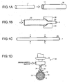
- FIGS. 1A to 1D are explanatory diagrams schematically illustrating a part of the method for producing the highly elastic stent according to an embodiment of the present invention.
- the method for producing the highly elastic stent includes an insertion step, a tube drawing step, a holding step, a cutting step, and a removal step.
- the insertion step is, as illustrated in FIG. 1A , a step of inserting a rod-shaped core metal 1 made of steel into a hollow portion 11 of a tube-shaped stent base 10 having, for example, a Ti-Ni alloy as a core (core material).
- the stent base 10 is formed by performing hot processing, machining process, and rolling processing on, for example, a Ti-Ni alloy ingot.
- the core metal 1 has a size with an outside diameter nearly fitting to an inside diameter of the stent base 10.
- the tube drawing step is, as illustrated in FIG.1B , a step of shrinking, with a die 20 or the like, the diameter of the stent base 10 with the core metal 1 inserted therein so as to lengthen the overall length of the stent base 10.
- the stent base 10 may be cut to a desired length.
- the holding step is, as illustrated in FIG. 1C , a step of applying heat treatment to the stent base 10 drawn at the tube drawing step for a predetermined time at a desired temperature while holding the stent base 10 in a linear state.
- the heat treatment is preferably applied for approximately 30 minutes at approximately 300°C.
- the holding step is not an essential step, but a step performed as necessary.
- applying the heat treatment at approximately 300°C as described at the holding step above does not cause deterioration of metal, and may not have an adverse effect at a subsequent expansion processing step.
- the cutting step is, as illustrated in FIG. 1D , a step of forming slots 13 by cutting slot forming portions 12 of the stent base 10 with, for example, a laser 30 that uses a water jet as a waveguide of a laser light, such as referred to as water laser.
- the water laser 30 injects pressurized water from a nozzle 31 to form a water jet 32 reaching the stent base 10 serving as a target object, and irradiates the slot forming portions 12 with the laser light 34 that passes through a lens 33 and is emitted from the nozzle 31 while being reflected in the water jet 32, so as to cut the slot forming portions 12.
- the water laser 30 described above it is possible to cut the slot forming portions 12 with the laser light 34 while suppressing a heat effect by reflection, scattering, and the like of the laser light 34 on a periphery of the slot forming portions 12 and cooling the slot forming portions 12; in other words, it is possible to form the slots 13 by cutting desired portions of the stent base 10 with the core metal 1 inserted therein.
- the water laser 30 is cited here as an example.
- any type of laser light 34 can be applied to the present invention if the laser light 34 can cut the slot forming portions 12 while suppressing the heat effects by the laser light 34 on the periphery of the slot forming portions 12.
- a pulsed laser can be used.
- FIGS. 2A to 2C are explanatory diagram schematically illustrating the removal step performed after the steps illustrated in FIGS. 1A to 1D .
- the removal step is a step of removing the core metal 1 from a stent ST that has been obtained by forming the slots 13 in the stent base 10.
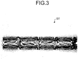
- the stent ST with the core metal 1 inserted therein is immersed in a chemical treatment liquid 40 such as a nitric acid solution. Then, as illustrated in FIG. 2B , the core metal 1 is dissolved. Thereafter, as illustrated in FIG. 2C , the core metal 1 is removed. As a result, the stent ST illustrated in FIG. 3 is obtained.
- a chemical treatment liquid 40 such as a nitric acid solution.
- FIGS. 4A to 4D are explanatory diagram schematically illustrating the expansion processing step performed after the removal step illustrated in FIGS. 2A to 2C .
- the expansion processing step is a step of expanding, to a desired diameter, the diameter of the stent ST from which the core metal 1 has been removed at the removal step, i.e., the stent ST with its diameter reduced.
- a jig 50 having a tapered shape at an end thereof is inserted into the hollow portion of the stent ST with its diameter reduced.
- the stent ST is placed in a state with its diameter expanded so as to have an inside diameter fitting to the outside diameter of the jig 50.
- the stent ST with its diameter expanded by inserting therein the jig 50 as described above is placed under a thermal atmosphere of, for example, 350°C or below, preferably 300°C or below, as illustrated in FIG. 4C , and is subjected to heat treatment for a predetermined time. This heat treatment is applied for the purpose of shape fixation when the stent ST is expanded.
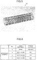
- the jig 50 is removed so as to obtain the stent ST as illustrated in FIG. 5 .
- the highly elastic stent ST produced by such a production method has been formed, in the production process, with the slots 13 in the stent base 10 by the laser processing in the state in which the core metal 1 is inserted in the hollow portion 11 of the stent base 10; in other words, the slots 13 have been formed by the laser processing while the linearity of the stent base 10 is maintained only with the heat treatment at 300°C or below without performing the heat straightening by heating to 500°C or above as in the conventional manner.
- the highly elastic stent ST has such a property that load increases with displacement without exhibiting a distinct yield on load-displacement curves obtained by a compression test and a bending test, in the same manner as a stress-strain curve in tension of a wire rod made of a Ti-Ni alloy.
- the highly elastic stent ST obtained in accordance with the present embodiment has a high stress function, and excels in storage characteristics because existing characteristics can be maintained even if thinning is carried out. Moreover, the highly elastic stent ST can be repeatedly used, thus being excellent in durability. Therefore, applying the laser processing to the tube-shaped stent base 10 does not cause performance deterioration.
- alloys practicable in the present invention include not only the Ti-Ni alloy, which exhibits superelasticity at body temperature of a living human being, but also Ti-Ni-X alloys and others (Cu group and Fe group alloys, etc.) with a third element added therewith, SUS, Co-Cr alloys, and Mg alloys.
- a Ti-Ni alloy ingot that contains 51% of Ni and the remaining part consisting of Ti is formed by hot processing into a rod of ⁇ 17 mm, and then, by machining process, into a pipe of ⁇ 15 mm ⁇ 11 mm. Thereafter, the pipe is formed by rolling processing into a size of ⁇ 8.0 mm ⁇ ⁇ 7.0 mm. Then, steel is inserted as the core metal (1), and wire-drawing processing is applied in the same manner as wire rod processing to form a tube (stent base (10)) of ⁇ 1.8 mm ⁇ ⁇ 1.4 mm with a cold working rate of 50%.
- the tube After being cut into a length of approximately 2 m, the tube is formed into a linear tube with the core metal (stent base (10) with the core metal) by using a cold wire straightener (straightening with dies for wire). Thereafter, the linear tube with the core metal is heat-treated for 30 minutes at 300°C.
- the heat-treated linear tube with the core metal of ⁇ 1.8 mm is formed with the slots (13) using a laser beam machine to be made into a stent.
- the laser beam machine is a device in which a laser is shielded by water.
- the core metal (1) is removed from the stent by the chemical treatment (dissolution in a nitric acid solution), and after applying superelastic treatment for 30 minutes at 300°C, electrolytic grinding surface treatment is applied to obtain the stent (ST) in Example 1.
- a Ti-Ni alloy ingot that contains 51% of Ni and the remaining part consisting of Ti is formed by the hot processing into a rod of ⁇ 17 mm, and then, by the machining process, into a pipe of ⁇ 15 mm ⁇ 2 mm. Thereafter, the pipe is processed by the rolling processing, and then by the wire-drawing processing with the core metal (1) inserted therein to be formed into a tube (stent base (10)) of ⁇ 6.0 mm ⁇ 5.6 mm with a cold working rate of 30%. After being cut into a test piece of approximately 2 m, the tube is formed into a linear tube with the core metal (stent base (10) with the core metal) by using the cold wire straightener (straightening with dies for wire).
- the linear tube with the core metal of ⁇ 6.0 mm is formed with the slots (13) using the laser beam machine to be made into a stent.
- the laser beam machine is the device in which a laser is shielded by water.
- the core metal (1) is removed from the stent by the chemical treatment (dissolution in a nitric acid solution), and the electrolytic grinding surface treatment is applied to obtain the stent (ST) in Example 2.
- the point is that the stent in Example 2 is not heat-treated in the production process.
- a Ti-Ni alloy ingot that contains 51% of Ni and the remaining part consisting of Ti is formed by the hot processing into a rod of ⁇ 17 mm, and then, by the machining process, into a pipe of ⁇ 15 mm ⁇ 2 mm. Thereafter, the pipe is processed by the rolling processing, and then by the wire-drawing processing with the core metal (1) inserted therein to be formed into a tube (stent base (10)) of ⁇ 6.0 mm ⁇ 5.6 mm with a cold working rate of 30%. After being cut into a test piece of approximately 2 m, the tube is formed into a linear tube with the core metal (stent base (10) with the core metal) by using the cold wire straightener (straightening with dies for wire). Thereafter, the linear tube with the core metal is heat-treated for 30 minutes at 300°C.
- the heat-treated linear tube with the core metal ⁇ 6.0 mm is formed with the slots (13) using the laser beam machine to be made into a stent.
- the laser beam machine is the device in which a laser is shielded by water.
- the core metal (1) is removed from the stent by the chemical treatment (dissolution in a nitric acid solution), and the electrolytic grinding surface treatment is applied to obtain the stent (ST) in Example 3.
- a linear tube with the core metal of ⁇ 1.8 mm is made, and the linear tube with the core metal is heat-treated for 30 minutes at 300°C.
- the core metal is removed from the heat-treated linear tube with the core metal.
- the tube from which the core metal had been removed could not maintain a sufficient linearity, and thereby could not be processed with a laser thereafter, thus failing to be formed into a stent.
- the same kind of Ti-Ni alloy ingot as that of Example 1 is formed by the hot processing into a rod of 17 mm, and then, by the machining process, into a pipe of 15 mm ⁇ 11 mm. Thereafter, the pipe is formed by the rolling processing into a size of ⁇ 8.0 mm ⁇ ⁇ 7.0 mm. Hardened steel is inserted as the core metal into the pipe, and the removal and insertion of the core metal is repeated for each of the wire-drawing passes.
- the pipe is formed into a tube of ⁇ 1.8 mm ⁇ ⁇ 1.4 mm with a cold working rate of 50%, and cut into a length of approximately 2 m. Note that a wire drawing rate of 20% to 30% is normally preferred to be obtained from each pass.
- the tube having undergone the heat straightening process is formed with the slots by the laser beam machine. After being subjected to the superelastic treatment for 10 minutes at 500°C to be increased in diameter successively from ⁇ 2.0 mm, ⁇ 3.0 mm, ⁇ 4.0 mm, ⁇ 5.0 mm, up to ⁇ 6.0 mm, the tube is subjected to the electrolytic grinding surface treatment to obtain a stent serving as Comparative Example 2.
- a tube of ⁇ 1.8 mm ⁇ 1.4 mm with a cold working rate of 50% is obtained.
- the tube After being cut into a length of approximately 2 m, the tube is formed into a linear tube with the core metal by using the cold wire straightener (straightening with dies for wire). Thereafter, the linear tube with the core metal is subjected to the heat straightening process for 10 minutes at 500°C.
- the heat-straightened linear tube with the core metal of ⁇ 1.8 mm is formed with the slots by the laser beam machine to be made into a stent.
- the laser beam machine is the device in which a laser is shielded by water.
- the core metal is removed from the stent by the chemical treatment (dissolution in a nitric acid solution).
- the electrolytic grinding surface treatment is applied to obtain the stent serving as Comparative Example 3.
- Example 3 By the same method as that of Example 3, a tube of ⁇ 6.0 mm ⁇ 5.6 mm with a cold working rate of 30% is obtained. After being cut into a length of approximately 2 m, the tube is formed into a linear tube with the core metal by using the cold wire straightener (straightening with dies for wire). Thereafter, the linear tube with the core metal is subjected to the heat straightening process for 10 minutes at 500°C.
- the heat-straightened linear tube with the core metal of ⁇ 6.0 mm is formed with the slots by the laser beam machine to be made into a stent.
- the laser beam machine is the device in which a laser is shielded by water.
- the core metal is removed from the stent by the chemical treatment (dissolution in a nitric acid solution).
- the electrolytic grinding surface treatment is applied to obtain the stent serving as Comparative Example 4.
- a Ti-Ni alloy that contains 51% of Ni and the remaining part consisting of Ti is processed by wire-drawing processing to obtain a wire of ⁇ 0.35 mm with a cold working rate of 50%.
- the wire is subjected to a tensile test to conduct a mechanical property evaluation (stress at a 2% elongation on the stress-strain (S-S) curve).
- Test materials are as follows: material cold-processed; material heat-treated for 30 minutes at 200°C; material heat-treated for 30 minutes at 300°C; and material heat-treated for 10 minutes at 500°C.
- FIG. 7 illustrates results of the S-S curves in the tensile tests of the following test materials illustrated in FIG. 6 : the cold-worked wire of 0.35 mm work-hardened (reference example 1); the material heat-treated for 30 minutes at 200°C (reference example 2); the material heat-treated for 30 minutes at 300°C (reference example 3); and the material heat-treated for 10 minutes at 500°C (reference example 4).
- each of Reference Examples 1 to 3 exhibits, on each of the S-S curves, a substantially linear load change in a loading-unloading cycle without exhibiting a distinct yield, and has a slight amount of hysteresis.
- Reference Example 4 exhibits a distinct yield and a plateau.
- each of the stents of Examples 1 to 3 has such a property that load increases with displacement without exhibiting a distinct yield on each of the load-displacement curves obtained by the compression test and the bending test, in the same manner as the stress-strain curve in tension of the wire rod made of the Ti-Ni alloy.
- a Co-Cr alloy ingot is formed by the hot processing into a rod of ⁇ 17 mm, and then, by the machining process, into a pipe of ⁇ 15 mm ⁇ 11 mm. Thereafter, the pipe is formed by the rolling processing into a size of ⁇ 8.0 mm ⁇ 7.0 mm. Then, steel is inserted as the core metal (1), and the wire-drawing processing is applied in the same manner as the wire rod processing to form a tube (stent base (10)) of ⁇ 1.8 mm ⁇ 1.4 mm with a cold working rate of 50%. After being cut into a length of approximately 2 m, the tube is formed into a linear tube with the core metal (stent base (10) with the core metal) by using the cold wire straightener (straightening with dies for wire).
- the linear tube with the core metal is formed with the slots (13) using the laser beam machine to be made into a stent.
- the laser beam machine is the device in which a laser is shielded by water.
- the core metal (1) is removed from the stent by the chemical treatment (dissolution in a nitric acid solution), and the electrolytic grinding surface treatment is applied to obtain the stent (ST) in Example 4.
- a linear tube with the core metal of ⁇ 1.8 mm is obtained.
- the linear tube with the core metal is formed with the slots by the laser beam machine to be made into a stent.
- the laser beam machine is the device in which a laser is shielded by water.
- the core metal is removed from the stent by the chemical treatment (dissolution in a nitric acid solution).
- the electrolytic grinding surface treatment is applied to obtain the stent serving as Comparative Example 5.
- a Co-Cr alloy (for industrial use) is processed by the wire-drawing processing to obtain a wire of ⁇ 0.2 mm with a cold working rate of 95%.
- the wire is subjected to the tensile test to conduct the mechanical property evaluation (stress at a 2% elongation on the stress-strain (S-S) curve).
- Test materials are material cold-processed (reference example 5) and material heat-treated at 800°C (reference example 6).
- FIG. 11 illustrates S-S curves of Reference Example 5
- FIG. 12 illustrates S-S curves of Reference Example 6. As illustrated in FIG.
- Reference Example 5 exhibits, on each of the S-S curves, a substantially linear load change in a loading-unloading cycle without exhibiting a distinct yield, and has a slight amount of hysteresis. As illustrated in FIG. 12 , Reference Example 6 exhibits a distinct yield and a plateau.
- the radial force evaluations are performed for the stent of Example 4 and for the stent of Comparative Example 5, which have been described above.
- the stent of Example 4 exhibited an S-S curve similar to that illustrated in FIG. 11
- the stent of Comparative Example 5 exhibited an S-S curve similar to that illustrated in FIG. 12 .
- the stent of Example 4 has such a property that load increases with displacement without exhibiting a distinct yield on each of the load-displacement curves obtained by the compression test and the bending test, in the same manner as the stress-strain curve in tension of the wire rod made of a Co-Cr alloy.
Landscapes
- Health & Medical Sciences (AREA)
- Engineering & Computer Science (AREA)
- Biomedical Technology (AREA)
- Optics & Photonics (AREA)
- Physics & Mathematics (AREA)
- Transplantation (AREA)
- Heart & Thoracic Surgery (AREA)
- Veterinary Medicine (AREA)
- Cardiology (AREA)
- Oral & Maxillofacial Surgery (AREA)
- Public Health (AREA)
- General Health & Medical Sciences (AREA)
- Animal Behavior & Ethology (AREA)
- Vascular Medicine (AREA)
- Life Sciences & Earth Sciences (AREA)
- Plasma & Fusion (AREA)
- Mechanical Engineering (AREA)
- Gastroenterology & Hepatology (AREA)
- Pulmonology (AREA)
- Media Introduction/Drainage Providing Device (AREA)
Claims (4)
- Procédé de production d'un stent (ST), le procédé comprenant :une étape d'insertion consistant à insérer un métal de noyau en forme de tige (1) dans une portion creuse (11) d'une base de stent en forme de tube (10) ;une étape d'étirage de tube consistant à allonger une longueur totale de la base de stent (10) avec le métal de noyau (11) inséré dans celle-ci en réduisant un diamètre de la base de stent (10);une étape de coupe consistant à maintenir, au besoin, une linéarité de la base de stent (10) étirée avec le métal de noyau inséré dans celle-ci, et ensuite, consistant à couper des portions de formation de fente (12) avec une lumière laser tout en supprimant un effet de chaleur par la lumière laser sur une périphérie des portions de formation de fente (12) de sorte à former des fentes (13) et ainsi fabriquer un stent; etune étape de retrait consistant à retirer le métal de noyau (1) du stent.
- Procédé de production du stent (ST) selon la revendication 1, le procédé comprenant en outre une étape de traitement d'expansion consistant à étendre le stent à partir duquel le métal de noyau (1) a été retiré à l'étape de retrait jusqu'à un diamètre prédéterminé tout en effectuant un traitement thermique sur le stent à 350°C ou moins.
- Procédé de production du stent (ST) selon la revendication 1 ou 2, dans lequel l'étape de coupe est une étape de formation des fentes (13) en coupant les portions de formation de fente (12) avec un laser qui utilise un jet d'eau (32), qui est formé de sorte à atteindre la base de stent (10), comme guide d'onde de la lumière laser.
- Procédé de production du stent (ST) selon les revendications 1 à 3, dans lequel le stent est fait de l'un quelconque d'un alliage de Ti-Ni, d'un alliage de Co-Cr, d'un alliage de Mg et d'un alliage inoxydable.
Applications Claiming Priority (3)
| Application Number | Priority Date | Filing Date | Title |
|---|---|---|---|
| JP2010160397 | 2010-07-15 | ||
| JP2010293563 | 2010-12-28 | ||
| PCT/JP2011/066240 WO2012008579A1 (fr) | 2010-07-15 | 2011-07-15 | Stent à module d'élasticité élevé et son procédé de production |
Publications (3)
| Publication Number | Publication Date |
|---|---|
| EP2594232A1 EP2594232A1 (fr) | 2013-05-22 |
| EP2594232A4 EP2594232A4 (fr) | 2016-08-31 |
| EP2594232B1 true EP2594232B1 (fr) | 2017-09-20 |
Family
ID=45469573
Family Applications (1)
| Application Number | Title | Priority Date | Filing Date |
|---|---|---|---|
| EP11806909.5A Not-in-force EP2594232B1 (fr) | 2010-07-15 | 2011-07-15 | Stent à module d'élasticité élevé et son procédé de production |
Country Status (4)
| Country | Link |
|---|---|
| US (2) | US20130204391A1 (fr) |
| EP (1) | EP2594232B1 (fr) |
| JP (1) | JP5972789B2 (fr) |
| WO (1) | WO2012008579A1 (fr) |
Families Citing this family (8)
| Publication number | Priority date | Publication date | Assignee | Title |
|---|---|---|---|---|
| US9422615B2 (en) * | 2011-09-16 | 2016-08-23 | W. L. Gore & Associates, Inc. | Single step shape memory alloy expansion |
| JP6349588B2 (ja) * | 2012-04-11 | 2018-07-04 | クリノ株式会社 | ステントの製造方法 |
| JP6023878B2 (ja) * | 2013-04-18 | 2016-11-09 | 株式会社パイオラックスメディカルデバイス | ステント及びその製造方法 |
| HK1250325B (zh) * | 2015-07-23 | 2019-12-13 | 奥普特米德医疗器械股份有限公司 | 支架 |
| CN110191971A (zh) | 2017-01-10 | 2019-08-30 | 不二轻金属株式会社 | 镁合金 |
| CN110234366B (zh) * | 2017-01-30 | 2021-11-02 | 株式会社日本医疗机器技研 | 高功能生物可吸收支架 |
| CN109259911A (zh) * | 2018-10-10 | 2019-01-25 | 苏州脉悦医疗科技有限公司 | 一种高弹性支架的制备方法 |
| JP6852142B2 (ja) * | 2019-11-22 | 2021-03-31 | オプティメド メディツィニッシェ インストゥルメンテ ゲーエムベーハーOptimed Medizinische Instrumente Gmbh | ステント |
Family Cites Families (28)
| Publication number | Priority date | Publication date | Assignee | Title |
|---|---|---|---|---|
| US3174851A (en) | 1961-12-01 | 1965-03-23 | William J Buehler | Nickel-base alloys |
| JP2961287B2 (ja) * | 1991-10-18 | 1999-10-12 | グンゼ株式会社 | 生体管路拡張具、その製造方法およびステント |
| JPH05293175A (ja) | 1992-04-16 | 1993-11-09 | Nippon Seisen Co Ltd | カテーテル用ガイドワイヤ |
| EP0753080A1 (fr) | 1994-03-31 | 1997-01-15 | Petrus Antonius Besselink | Procede de traitement d'alliage nickel-titane-niobium et articles fabriques dans cet alliage |
| JP3566986B2 (ja) | 1994-06-17 | 2004-09-15 | テルモ株式会社 | 生体内留置用ステントの製造方法 |
| EP1051953A3 (fr) | 1994-06-17 | 2001-02-28 | Terumo Kabushiki Kaisha | Stent permanent et procédé pour fabriquer ce stent |
| JP3577353B2 (ja) | 1995-01-27 | 2004-10-13 | テルモ株式会社 | 生体内留置用ステント |
| AU762087B2 (en) * | 1998-07-31 | 2003-06-19 | Evysio Medical Devices Ulc | Small vessel expandable stent and method for production of same |
| US6508803B1 (en) | 1998-11-06 | 2003-01-21 | Furukawa Techno Material Co., Ltd. | Niti-type medical guide wire and method of producing the same |
| JP3547366B2 (ja) | 1999-09-27 | 2004-07-28 | 株式会社古河テクノマテリアル | 医療用ガイドワイヤに用いられる広ひずみ範囲高弾性Ni−Ti系合金ワイヤの製造方法 |
| JP2001187150A (ja) * | 1999-10-20 | 2001-07-10 | Tokin Corp | ステント |
| EP1132058A1 (fr) * | 2000-03-06 | 2001-09-12 | Advanced Laser Applications Holding S.A. | Prothèse intravasculaire |
| US6602272B2 (en) * | 2000-11-02 | 2003-08-05 | Advanced Cardiovascular Systems, Inc. | Devices configured from heat shaped, strain hardened nickel-titanium |
| US6551341B2 (en) * | 2001-06-14 | 2003-04-22 | Advanced Cardiovascular Systems, Inc. | Devices configured from strain hardened Ni Ti tubing |
| JP4133207B2 (ja) * | 2001-10-22 | 2008-08-13 | テルモ株式会社 | 生体内留置用ステントの製造方法 |
| ATE380001T1 (de) * | 2001-10-22 | 2007-12-15 | Terumo Corp | Stent und verfahren zu dessen herstellung |
| EP1348402A1 (fr) * | 2002-03-29 | 2003-10-01 | Advanced Laser Applications Holding S.A. | Endoprothèse intraluminale, expansible radialement et perforée pour la distribution de médicament |
| US6696666B2 (en) * | 2002-07-03 | 2004-02-24 | Scimed Life Systems, Inc. | Tubular cutting process and system |
| US7942892B2 (en) * | 2003-05-01 | 2011-05-17 | Abbott Cardiovascular Systems Inc. | Radiopaque nitinol embolic protection frame |
| JP2005080881A (ja) * | 2003-09-09 | 2005-03-31 | Nec Tokin Corp | 金属メッシュ管とその製造方法 |
| JP2005198853A (ja) * | 2004-01-16 | 2005-07-28 | Asukuremedeiku:Kk | ステントの製造方法 |
| US20060136037A1 (en) | 2004-10-14 | 2006-06-22 | Debeer Nicholas C | Small vessel stent designs |
| JP2006247139A (ja) * | 2005-03-10 | 2006-09-21 | Homuzu Giken:Kk | ステントの製造方法及びステント |
| US7622070B2 (en) * | 2005-06-20 | 2009-11-24 | Advanced Cardiovascular Systems, Inc. | Method of manufacturing an implantable polymeric medical device |
| US20070293939A1 (en) * | 2006-05-15 | 2007-12-20 | Abbott Laboratories | Fatigue resistant endoprostheses |
| JP5008181B2 (ja) * | 2006-11-07 | 2012-08-22 | 株式会社日本ステントテクノロジー | ステント |
| JP5078346B2 (ja) | 2006-12-28 | 2012-11-21 | テルモ株式会社 | 自己拡張型ステント |
| US8373090B2 (en) * | 2009-09-04 | 2013-02-12 | Abbott Cardiovascular Systems Inc. | Method and apparatus to prevent stent damage caused by laser cutting |
-
2011
- 2011-07-15 JP JP2012524610A patent/JP5972789B2/ja not_active Expired - Fee Related
- 2011-07-15 EP EP11806909.5A patent/EP2594232B1/fr not_active Not-in-force
- 2011-07-15 US US13/810,185 patent/US20130204391A1/en not_active Abandoned
- 2011-07-15 WO PCT/JP2011/066240 patent/WO2012008579A1/fr not_active Ceased
-
2014
- 2014-08-14 US US14/460,351 patent/US9480550B2/en not_active Expired - Fee Related
Non-Patent Citations (1)
| Title |
|---|
| None * |
Also Published As
| Publication number | Publication date |
|---|---|
| US20130204391A1 (en) | 2013-08-08 |
| US20150014288A1 (en) | 2015-01-15 |
| JP5972789B2 (ja) | 2016-08-17 |
| US9480550B2 (en) | 2016-11-01 |
| EP2594232A4 (fr) | 2016-08-31 |
| WO2012008579A1 (fr) | 2012-01-19 |
| EP2594232A1 (fr) | 2013-05-22 |
| JPWO2012008579A1 (ja) | 2013-09-09 |
Similar Documents
| Publication | Publication Date | Title |
|---|---|---|
| US9480550B2 (en) | Highly elastic stent and production method for highly elastic stent | |
| Kapoor | Nitinol for medical applications: a brief introduction to the properties and processing of nickel titanium shape memory alloys and their use in stents | |
| Poncin et al. | Stent tubing: understanding the desired attributes | |
| CN100502805C (zh) | 气囊扩张型超弹性支架及其制造方法 | |
| US20070293939A1 (en) | Fatigue resistant endoprostheses | |
| KR102626287B1 (ko) | 마그네슘 기반 흡수성 합금 | |
| US20120255657A1 (en) | Method of improving the properties of a component of a medical device comprising a nickel-titanium-chromium alloy | |
| JP5684133B2 (ja) | ステント | |
| EP3538681B1 (fr) | Alliages de bêta-titane sans nickel à mémoire de forme et propriétés super-élastiques | |
| US20130096669A1 (en) | Partially annealed stent | |
| EP2098195A1 (fr) | Stent à auto-expansion | |
| EP2987470A1 (fr) | Endoprothèse et son procédé de production | |
| JP7726442B2 (ja) | 超弾性ステントおよび超弾性ステントの製造方法、ならびに合金チューブおよび合金チューブの製造方法 | |
| US20160243289A1 (en) | MEDICAL Ti-Ni ALLOY | |
| AU2018214780B2 (en) | Bioabsorbable stent | |
| JP6349588B2 (ja) | ステントの製造方法 | |
| US20140190587A1 (en) | Device and Method for Crimping an Implant | |
| JP7689687B2 (ja) | 医療用器具 | |
| JP2014036817A (ja) | 機能性金属チューブ部材およびその製造方法 | |
| JP5610863B2 (ja) | ステントおよびステントデリバリーカテーテル | |
| JP2016073589A (ja) | 複機能ステント | |
| JP2008036076A (ja) | バルーン拡張型ステントおよびその製造方法 | |
| WO2023239573A1 (fr) | Traitement d'alliages cobalt-tungstène | |
| JP2016059504A (ja) | 柔軟性が向上したステント | |
| JP2014204940A (ja) | 予ひずみ負荷超弾性ステント |
Legal Events
| Date | Code | Title | Description |
|---|---|---|---|
| PUAI | Public reference made under article 153(3) epc to a published international application that has entered the european phase |
Free format text: ORIGINAL CODE: 0009012 |
|
| 17P | Request for examination filed |
Effective date: 20130213 |
|
| AK | Designated contracting states |
Kind code of ref document: A1 Designated state(s): AL AT BE BG CH CY CZ DE DK EE ES FI FR GB GR HR HU IE IS IT LI LT LU LV MC MK MT NL NO PL PT RO RS SE SI SK SM TR |
|
| DAX | Request for extension of the european patent (deleted) | ||
| RAP1 | Party data changed (applicant data changed or rights of an application transferred) |
Owner name: CLINO LTD. Owner name: PIOLAX MEDICAL DEVICES, INC. |
|
| RAP1 | Party data changed (applicant data changed or rights of an application transferred) |
Owner name: JAPAN MEDICAL DEVICE TECHNOLOGY CO., LTD. Owner name: CLINO LTD. Owner name: PIOLAX MEDICAL DEVICES, INC. |
|
| RA4 | Supplementary search report drawn up and despatched (corrected) |
Effective date: 20160802 |
|
| RIC1 | Information provided on ipc code assigned before grant |
Ipc: A61F 2/82 20060101AFI20160727BHEP Ipc: A61F 2/91 20130101ALI20160727BHEP |
|
| GRAP | Despatch of communication of intention to grant a patent |
Free format text: ORIGINAL CODE: EPIDOSNIGR1 |
|
| INTG | Intention to grant announced |
Effective date: 20170519 |
|
| GRAS | Grant fee paid |
Free format text: ORIGINAL CODE: EPIDOSNIGR3 |
|
| GRAA | (expected) grant |
Free format text: ORIGINAL CODE: 0009210 |
|
| AK | Designated contracting states |
Kind code of ref document: B1 Designated state(s): AL AT BE BG CH CY CZ DE DK EE ES FI FR GB GR HR HU IE IS IT LI LT LU LV MC MK MT NL NO PL PT RO RS SE SI SK SM TR |
|
| REG | Reference to a national code |
Ref country code: GB Ref legal event code: FG4D |
|
| REG | Reference to a national code |
Ref country code: CH Ref legal event code: EP |
|
| REG | Reference to a national code |
Ref country code: AT Ref legal event code: REF Ref document number: 929566 Country of ref document: AT Kind code of ref document: T Effective date: 20171015 |
|
| REG | Reference to a national code |
Ref country code: IE Ref legal event code: FG4D |
|
| REG | Reference to a national code |
Ref country code: DE Ref legal event code: R096 Ref document number: 602011041776 Country of ref document: DE |
|
| REG | Reference to a national code |
Ref country code: NL Ref legal event code: MP Effective date: 20170920 |
|
| PG25 | Lapsed in a contracting state [announced via postgrant information from national office to epo] |
Ref country code: SE Free format text: LAPSE BECAUSE OF FAILURE TO SUBMIT A TRANSLATION OF THE DESCRIPTION OR TO PAY THE FEE WITHIN THE PRESCRIBED TIME-LIMIT Effective date: 20170920 Ref country code: FI Free format text: LAPSE BECAUSE OF FAILURE TO SUBMIT A TRANSLATION OF THE DESCRIPTION OR TO PAY THE FEE WITHIN THE PRESCRIBED TIME-LIMIT Effective date: 20170920 Ref country code: LT Free format text: LAPSE BECAUSE OF FAILURE TO SUBMIT A TRANSLATION OF THE DESCRIPTION OR TO PAY THE FEE WITHIN THE PRESCRIBED TIME-LIMIT Effective date: 20170920 Ref country code: HR Free format text: LAPSE BECAUSE OF FAILURE TO SUBMIT A TRANSLATION OF THE DESCRIPTION OR TO PAY THE FEE WITHIN THE PRESCRIBED TIME-LIMIT Effective date: 20170920 Ref country code: NO Free format text: LAPSE BECAUSE OF FAILURE TO SUBMIT A TRANSLATION OF THE DESCRIPTION OR TO PAY THE FEE WITHIN THE PRESCRIBED TIME-LIMIT Effective date: 20171220 |
|
| REG | Reference to a national code |
Ref country code: LT Ref legal event code: MG4D |
|
| REG | Reference to a national code |
Ref country code: AT Ref legal event code: MK05 Ref document number: 929566 Country of ref document: AT Kind code of ref document: T Effective date: 20170920 |
|
| PG25 | Lapsed in a contracting state [announced via postgrant information from national office to epo] |
Ref country code: RS Free format text: LAPSE BECAUSE OF FAILURE TO SUBMIT A TRANSLATION OF THE DESCRIPTION OR TO PAY THE FEE WITHIN THE PRESCRIBED TIME-LIMIT Effective date: 20170920 Ref country code: BG Free format text: LAPSE BECAUSE OF FAILURE TO SUBMIT A TRANSLATION OF THE DESCRIPTION OR TO PAY THE FEE WITHIN THE PRESCRIBED TIME-LIMIT Effective date: 20171220 Ref country code: LV Free format text: LAPSE BECAUSE OF FAILURE TO SUBMIT A TRANSLATION OF THE DESCRIPTION OR TO PAY THE FEE WITHIN THE PRESCRIBED TIME-LIMIT Effective date: 20170920 Ref country code: GR Free format text: LAPSE BECAUSE OF FAILURE TO SUBMIT A TRANSLATION OF THE DESCRIPTION OR TO PAY THE FEE WITHIN THE PRESCRIBED TIME-LIMIT Effective date: 20171221 |
|
| PG25 | Lapsed in a contracting state [announced via postgrant information from national office to epo] |
Ref country code: NL Free format text: LAPSE BECAUSE OF FAILURE TO SUBMIT A TRANSLATION OF THE DESCRIPTION OR TO PAY THE FEE WITHIN THE PRESCRIBED TIME-LIMIT Effective date: 20170920 |
|
| PG25 | Lapsed in a contracting state [announced via postgrant information from national office to epo] |
Ref country code: RO Free format text: LAPSE BECAUSE OF FAILURE TO SUBMIT A TRANSLATION OF THE DESCRIPTION OR TO PAY THE FEE WITHIN THE PRESCRIBED TIME-LIMIT Effective date: 20170920 Ref country code: ES Free format text: LAPSE BECAUSE OF FAILURE TO SUBMIT A TRANSLATION OF THE DESCRIPTION OR TO PAY THE FEE WITHIN THE PRESCRIBED TIME-LIMIT Effective date: 20170920 Ref country code: PL Free format text: LAPSE BECAUSE OF FAILURE TO SUBMIT A TRANSLATION OF THE DESCRIPTION OR TO PAY THE FEE WITHIN THE PRESCRIBED TIME-LIMIT Effective date: 20170920 Ref country code: CZ Free format text: LAPSE BECAUSE OF FAILURE TO SUBMIT A TRANSLATION OF THE DESCRIPTION OR TO PAY THE FEE WITHIN THE PRESCRIBED TIME-LIMIT Effective date: 20170920 |
|
| PG25 | Lapsed in a contracting state [announced via postgrant information from national office to epo] |
Ref country code: IT Free format text: LAPSE BECAUSE OF FAILURE TO SUBMIT A TRANSLATION OF THE DESCRIPTION OR TO PAY THE FEE WITHIN THE PRESCRIBED TIME-LIMIT Effective date: 20170920 Ref country code: AT Free format text: LAPSE BECAUSE OF FAILURE TO SUBMIT A TRANSLATION OF THE DESCRIPTION OR TO PAY THE FEE WITHIN THE PRESCRIBED TIME-LIMIT Effective date: 20170920 Ref country code: SM Free format text: LAPSE BECAUSE OF FAILURE TO SUBMIT A TRANSLATION OF THE DESCRIPTION OR TO PAY THE FEE WITHIN THE PRESCRIBED TIME-LIMIT Effective date: 20170920 Ref country code: IS Free format text: LAPSE BECAUSE OF FAILURE TO SUBMIT A TRANSLATION OF THE DESCRIPTION OR TO PAY THE FEE WITHIN THE PRESCRIBED TIME-LIMIT Effective date: 20180120 Ref country code: SK Free format text: LAPSE BECAUSE OF FAILURE TO SUBMIT A TRANSLATION OF THE DESCRIPTION OR TO PAY THE FEE WITHIN THE PRESCRIBED TIME-LIMIT Effective date: 20170920 Ref country code: EE Free format text: LAPSE BECAUSE OF FAILURE TO SUBMIT A TRANSLATION OF THE DESCRIPTION OR TO PAY THE FEE WITHIN THE PRESCRIBED TIME-LIMIT Effective date: 20170920 |
|
| REG | Reference to a national code |
Ref country code: DE Ref legal event code: R097 Ref document number: 602011041776 Country of ref document: DE |
|
| REG | Reference to a national code |
Ref country code: FR Ref legal event code: PLFP Year of fee payment: 8 |
|
| PLBE | No opposition filed within time limit |
Free format text: ORIGINAL CODE: 0009261 |
|
| STAA | Information on the status of an ep patent application or granted ep patent |
Free format text: STATUS: NO OPPOSITION FILED WITHIN TIME LIMIT |
|
| PG25 | Lapsed in a contracting state [announced via postgrant information from national office to epo] |
Ref country code: DK Free format text: LAPSE BECAUSE OF FAILURE TO SUBMIT A TRANSLATION OF THE DESCRIPTION OR TO PAY THE FEE WITHIN THE PRESCRIBED TIME-LIMIT Effective date: 20170920 |
|
| 26N | No opposition filed |
Effective date: 20180621 |
|
| PG25 | Lapsed in a contracting state [announced via postgrant information from national office to epo] |
Ref country code: SI Free format text: LAPSE BECAUSE OF FAILURE TO SUBMIT A TRANSLATION OF THE DESCRIPTION OR TO PAY THE FEE WITHIN THE PRESCRIBED TIME-LIMIT Effective date: 20170920 |
|
| REG | Reference to a national code |
Ref country code: CH Ref legal event code: PL |
|
| PG25 | Lapsed in a contracting state [announced via postgrant information from national office to epo] |
Ref country code: LU Free format text: LAPSE BECAUSE OF NON-PAYMENT OF DUE FEES Effective date: 20180715 Ref country code: MC Free format text: LAPSE BECAUSE OF FAILURE TO SUBMIT A TRANSLATION OF THE DESCRIPTION OR TO PAY THE FEE WITHIN THE PRESCRIBED TIME-LIMIT Effective date: 20170920 |
|
| REG | Reference to a national code |
Ref country code: BE Ref legal event code: MM Effective date: 20180731 |
|
| REG | Reference to a national code |
Ref country code: IE Ref legal event code: MM4A |
|
| PG25 | Lapsed in a contracting state [announced via postgrant information from national office to epo] |
Ref country code: IE Free format text: LAPSE BECAUSE OF NON-PAYMENT OF DUE FEES Effective date: 20180715 Ref country code: CH Free format text: LAPSE BECAUSE OF NON-PAYMENT OF DUE FEES Effective date: 20180731 Ref country code: LI Free format text: LAPSE BECAUSE OF NON-PAYMENT OF DUE FEES Effective date: 20180731 |
|
| PG25 | Lapsed in a contracting state [announced via postgrant information from national office to epo] |
Ref country code: BE Free format text: LAPSE BECAUSE OF NON-PAYMENT OF DUE FEES Effective date: 20180731 |
|
| PGFP | Annual fee paid to national office [announced via postgrant information from national office to epo] |
Ref country code: FR Payment date: 20190718 Year of fee payment: 9 Ref country code: DE Payment date: 20190715 Year of fee payment: 9 |
|
| PGFP | Annual fee paid to national office [announced via postgrant information from national office to epo] |
Ref country code: GB Payment date: 20190718 Year of fee payment: 9 |
|
| PG25 | Lapsed in a contracting state [announced via postgrant information from national office to epo] |
Ref country code: MT Free format text: LAPSE BECAUSE OF NON-PAYMENT OF DUE FEES Effective date: 20180715 |
|
| PG25 | Lapsed in a contracting state [announced via postgrant information from national office to epo] |
Ref country code: TR Free format text: LAPSE BECAUSE OF FAILURE TO SUBMIT A TRANSLATION OF THE DESCRIPTION OR TO PAY THE FEE WITHIN THE PRESCRIBED TIME-LIMIT Effective date: 20170920 |
|
| PG25 | Lapsed in a contracting state [announced via postgrant information from national office to epo] |
Ref country code: PT Free format text: LAPSE BECAUSE OF FAILURE TO SUBMIT A TRANSLATION OF THE DESCRIPTION OR TO PAY THE FEE WITHIN THE PRESCRIBED TIME-LIMIT Effective date: 20170920 Ref country code: HU Free format text: LAPSE BECAUSE OF FAILURE TO SUBMIT A TRANSLATION OF THE DESCRIPTION OR TO PAY THE FEE WITHIN THE PRESCRIBED TIME-LIMIT; INVALID AB INITIO Effective date: 20110715 |
|
| PG25 | Lapsed in a contracting state [announced via postgrant information from national office to epo] |
Ref country code: CY Free format text: LAPSE BECAUSE OF FAILURE TO SUBMIT A TRANSLATION OF THE DESCRIPTION OR TO PAY THE FEE WITHIN THE PRESCRIBED TIME-LIMIT Effective date: 20170920 Ref country code: MK Free format text: LAPSE BECAUSE OF NON-PAYMENT OF DUE FEES Effective date: 20170920 |
|
| PG25 | Lapsed in a contracting state [announced via postgrant information from national office to epo] |
Ref country code: AL Free format text: LAPSE BECAUSE OF FAILURE TO SUBMIT A TRANSLATION OF THE DESCRIPTION OR TO PAY THE FEE WITHIN THE PRESCRIBED TIME-LIMIT Effective date: 20170920 |
|
| REG | Reference to a national code |
Ref country code: DE Ref legal event code: R119 Ref document number: 602011041776 Country of ref document: DE |
|
| GBPC | Gb: european patent ceased through non-payment of renewal fee |
Effective date: 20200715 |
|
| PG25 | Lapsed in a contracting state [announced via postgrant information from national office to epo] |
Ref country code: GB Free format text: LAPSE BECAUSE OF NON-PAYMENT OF DUE FEES Effective date: 20200715 Ref country code: FR Free format text: LAPSE BECAUSE OF NON-PAYMENT OF DUE FEES Effective date: 20200731 |
|
| PG25 | Lapsed in a contracting state [announced via postgrant information from national office to epo] |
Ref country code: DE Free format text: LAPSE BECAUSE OF NON-PAYMENT OF DUE FEES Effective date: 20210202 |