EP2594331A1 - Verfahren und Vorrichtung zur Begasung von Flüssigkeiten - Google Patents
Verfahren und Vorrichtung zur Begasung von Flüssigkeiten Download PDFInfo
- Publication number
- EP2594331A1 EP2594331A1 EP13154877.8A EP13154877A EP2594331A1 EP 2594331 A1 EP2594331 A1 EP 2594331A1 EP 13154877 A EP13154877 A EP 13154877A EP 2594331 A1 EP2594331 A1 EP 2594331A1
- Authority
- EP
- European Patent Office
- Prior art keywords
- mixing tube
- water
- opening
- section
- outlet opening
- Prior art date
- Legal status (The legal status is an assumption and is not a legal conclusion. Google has not performed a legal analysis and makes no representation as to the accuracy of the status listed.)
- Withdrawn
Links
Images
Classifications
-
- B—PERFORMING OPERATIONS; TRANSPORTING
- B01—PHYSICAL OR CHEMICAL PROCESSES OR APPARATUS IN GENERAL
- B01F—MIXING, e.g. DISSOLVING, EMULSIFYING OR DISPERSING
- B01F23/00—Mixing according to the phases to be mixed, e.g. dispersing or emulsifying
- B01F23/20—Mixing gases with liquids
- B01F23/21—Mixing gases with liquids by introducing liquids into gaseous media
- B01F23/213—Mixing gases with liquids by introducing liquids into gaseous media by spraying or atomising of the liquids
- B01F23/2132—Mixing gases with liquids by introducing liquids into gaseous media by spraying or atomising of the liquids using nozzles
-
- B—PERFORMING OPERATIONS; TRANSPORTING
- B01—PHYSICAL OR CHEMICAL PROCESSES OR APPARATUS IN GENERAL
- B01F—MIXING, e.g. DISSOLVING, EMULSIFYING OR DISPERSING
- B01F25/00—Flow mixers; Mixers for falling materials, e.g. solid particles
- B01F25/30—Injector mixers
- B01F25/31—Injector mixers in conduits or tubes through which the main component flows
- B01F25/312—Injector mixers in conduits or tubes through which the main component flows with Venturi elements; Details thereof
- B01F25/3124—Injector mixers in conduits or tubes through which the main component flows with Venturi elements; Details thereof characterised by the place of introduction of the main flow
- B01F25/31243—Eductor or eductor-type venturi, i.e. the main flow being injected through the venturi with high speed in the form of a jet
-
- B—PERFORMING OPERATIONS; TRANSPORTING
- B01—PHYSICAL OR CHEMICAL PROCESSES OR APPARATUS IN GENERAL
- B01F—MIXING, e.g. DISSOLVING, EMULSIFYING OR DISPERSING
- B01F23/00—Mixing according to the phases to be mixed, e.g. dispersing or emulsifying
- B01F23/20—Mixing gases with liquids
- B01F23/23—Mixing gases with liquids by introducing gases into liquid media, e.g. for producing aerated liquids
- B01F23/234—Surface aerating
-
- B—PERFORMING OPERATIONS; TRANSPORTING
- B01—PHYSICAL OR CHEMICAL PROCESSES OR APPARATUS IN GENERAL
- B01F—MIXING, e.g. DISSOLVING, EMULSIFYING OR DISPERSING
- B01F23/00—Mixing according to the phases to be mixed, e.g. dispersing or emulsifying
- B01F23/20—Mixing gases with liquids
- B01F23/23—Mixing gases with liquids by introducing gases into liquid media, e.g. for producing aerated liquids
- B01F23/234—Surface aerating
- B01F23/2341—Surface aerating by cascading, spraying or projecting a liquid into a gaseous atmosphere
- B01F23/23413—Surface aerating by cascading, spraying or projecting a liquid into a gaseous atmosphere using nozzles for projecting the liquid into the gas atmosphere
-
- B—PERFORMING OPERATIONS; TRANSPORTING
- B01—PHYSICAL OR CHEMICAL PROCESSES OR APPARATUS IN GENERAL
- B01F—MIXING, e.g. DISSOLVING, EMULSIFYING OR DISPERSING
- B01F25/00—Flow mixers; Mixers for falling materials, e.g. solid particles
- B01F25/30—Injector mixers
- B01F25/31—Injector mixers in conduits or tubes through which the main component flows
- B01F25/312—Injector mixers in conduits or tubes through which the main component flows with Venturi elements; Details thereof
- B01F25/3125—Injector mixers in conduits or tubes through which the main component flows with Venturi elements; Details thereof characteristics of the Venturi parts
- B01F25/31252—Nozzles
- B01F25/312521—Adjustable Venturi nozzle
-
- B—PERFORMING OPERATIONS; TRANSPORTING
- B01—PHYSICAL OR CHEMICAL PROCESSES OR APPARATUS IN GENERAL
- B01F—MIXING, e.g. DISSOLVING, EMULSIFYING OR DISPERSING
- B01F25/00—Flow mixers; Mixers for falling materials, e.g. solid particles
- B01F25/30—Injector mixers
- B01F25/31—Injector mixers in conduits or tubes through which the main component flows
- B01F25/312—Injector mixers in conduits or tubes through which the main component flows with Venturi elements; Details thereof
- B01F25/3125—Injector mixers in conduits or tubes through which the main component flows with Venturi elements; Details thereof characteristics of the Venturi parts
- B01F25/31253—Discharge
- B01F25/312532—Profiled, grooved, ribbed discharge conduit, or being provided with baffles
-
- B—PERFORMING OPERATIONS; TRANSPORTING
- B01—PHYSICAL OR CHEMICAL PROCESSES OR APPARATUS IN GENERAL
- B01F—MIXING, e.g. DISSOLVING, EMULSIFYING OR DISPERSING
- B01F25/00—Flow mixers; Mixers for falling materials, e.g. solid particles
- B01F25/30—Injector mixers
- B01F25/31—Injector mixers in conduits or tubes through which the main component flows
- B01F25/313—Injector mixers in conduits or tubes through which the main component flows wherein additional components are introduced in the centre of the conduit
- B01F25/3131—Injector mixers in conduits or tubes through which the main component flows wherein additional components are introduced in the centre of the conduit with additional mixing means other than injector mixers, e.g. screens, baffles or rotating elements
-
- B—PERFORMING OPERATIONS; TRANSPORTING
- B01—PHYSICAL OR CHEMICAL PROCESSES OR APPARATUS IN GENERAL
- B01F—MIXING, e.g. DISSOLVING, EMULSIFYING OR DISPERSING
- B01F33/00—Other mixers; Mixing plants; Combinations of mixers
- B01F33/80—Mixing plants; Combinations of mixers
- B01F33/81—Combinations of similar mixers, e.g. with rotary stirring devices in two or more receptacles
- B01F33/811—Combinations of similar mixers, e.g. with rotary stirring devices in two or more receptacles in two or more consecutive, i.e. successive, mixing receptacles or being consecutively arranged
-
- B—PERFORMING OPERATIONS; TRANSPORTING
- B01—PHYSICAL OR CHEMICAL PROCESSES OR APPARATUS IN GENERAL
- B01F—MIXING, e.g. DISSOLVING, EMULSIFYING OR DISPERSING
- B01F33/00—Other mixers; Mixing plants; Combinations of mixers
- B01F33/80—Mixing plants; Combinations of mixers
- B01F33/82—Combinations of dissimilar mixers
-
- B—PERFORMING OPERATIONS; TRANSPORTING
- B01—PHYSICAL OR CHEMICAL PROCESSES OR APPARATUS IN GENERAL
- B01F—MIXING, e.g. DISSOLVING, EMULSIFYING OR DISPERSING
- B01F23/00—Mixing according to the phases to be mixed, e.g. dispersing or emulsifying
- B01F23/20—Mixing gases with liquids
- B01F23/23—Mixing gases with liquids by introducing gases into liquid media, e.g. for producing aerated liquids
- B01F23/237—Mixing gases with liquids by introducing gases into liquid media, e.g. for producing aerated liquids characterised by the physical or chemical properties of gases or vapours introduced in the liquid media
- B01F23/2376—Mixing gases with liquids by introducing gases into liquid media, e.g. for producing aerated liquids characterised by the physical or chemical properties of gases or vapours introduced in the liquid media characterised by the gas being introduced
- B01F23/23761—Aerating, i.e. introducing oxygen containing gas in liquids
- B01F23/237611—Air
-
- Y—GENERAL TAGGING OF NEW TECHNOLOGICAL DEVELOPMENTS; GENERAL TAGGING OF CROSS-SECTIONAL TECHNOLOGIES SPANNING OVER SEVERAL SECTIONS OF THE IPC; TECHNICAL SUBJECTS COVERED BY FORMER USPC CROSS-REFERENCE ART COLLECTIONS [XRACs] AND DIGESTS
- Y02—TECHNOLOGIES OR APPLICATIONS FOR MITIGATION OR ADAPTATION AGAINST CLIMATE CHANGE
- Y02W—CLIMATE CHANGE MITIGATION TECHNOLOGIES RELATED TO WASTEWATER TREATMENT OR WASTE MANAGEMENT
- Y02W10/00—Technologies for wastewater treatment
- Y02W10/10—Biological treatment of water, waste water, or sewage
Definitions
- the invention relates to a method for aeration of water, in which a mixing tube air through an air inlet and water is supplied via a water inlet to form a mixture of air and water, wherein the water introduced centrally via a feed tube and the mouth opening into the mixing tube and in Area of the mouth opening is spread by impact on a spreader.
- the invention further relates to a device for carrying out the method.
- a generic device for aeration of water in which a supply tube protrudes centrally in a mixing tube and has a directed towards the outlet opening of the mixing tube orifice, wherein the feed tube is connected to a pressurized water source.
- an expansion body In the mouth of the feed tube an expansion body is arranged, which causes a spreading of the liquid and thus its mixing with the air to a mixture of water and air.
- the mixing tube consists of two in the flow direction successively arranged cone sections, which form a cross-sectional constriction at their ends facing each other.
- the mouth opening of the feed tube is arranged with respect to the cross-sectional constriction so that the mixing cone forming on exit of the water is not limited by the cross-sectional constriction.
- a device for ventilating urinals in which a feed tube for the supply of water protrudes centrally in a cylindrical mixing tube.
- the feed tube has an orifice and is connected to a pressurized water reservoir.
- an expansion body In the mouth of the feed tube, an expansion body is arranged, which causes a spreading of the water and thus its mixing with the air sucked thereby.
- sewage sludge is introduced via a curved pipe socket and a cone valve in a mixing tube.
- the plug valve has a valve body which is displaceably guided between a closed position and a downstream open position.
- the valve body is penetrated by a straight air supply pipe, which also acts as a valve rod and together with the valve body is guided axially displaceable.
- a disadvantage of this method is that the mixing between sewage sludge and air over the cross section is very uneven.
- hydrodynamic cavitation mixers for producing liquid systems, in particular emulsions, suspensions or the like, are known, in which cavitation zones are produced by special designs within a mixing tube, in which a coordinated bursting of cavitation bubbles in a local extent with simultaneous formation of pressure waves of high energy are generated ,
- Examples are the DE 44 33 744 A1 and DE 10 2005 037 026 A1 refer to.
- Kavitationsmischern is - as already in the device according to the CH 642 563 A5 - Air supplied centrally in a mixing tube, once with the liquid flow ( DE 44 33 744 A1 ) and once against the liquid flow ( DE 10 2005 037 026 A1 ). It is in the cavitation after the DE 44 33 744 A1 inserted into the central air supply pipe a cone body in the mouth opening.
- the invention has for its object to provide a method by which a much higher and uniform over the cross section enrichment of water with air is achieved. Another object is to provide a device suitable for carrying out the method.
- the object relating to the method is achieved according to the invention in that an acceleration of the mixture is effected by narrowing the flow cross section for the mixture downstream of the mouth opening, and that the water is spread by an expansion body is at least partially out of the mouth and out into the mixing tube.
- the cross-sectional constriction may be formed as a cone-shaped aperture with downstream narrowing cross-section. After the aperture, the mixing tube has its original cross section, so that after acceleration of the flow through the aperture creates a kind of diffuser effect.
- an expansion body In order to achieve a uniform spreading of the water, an expansion body should be used, which is formed axially symmetrical about an axis centered to the mouth opening axis. In this way, a splayed, in particular ring-shaped water jet with a large surface for mixing between water and air. It is useful for the spreading when the cross section of the expansion body increases in the flow direction. Particularly suitable for the spreading is the shape of a cone body, wherein the surface line may also be spherically concave and thus formed approximately a mushroom shape. However, especially with rectangular or square feed tube, the use of a pontoon body as an expansion body in question.
- the largest cross section of the expansion body should be larger than the opening cross section of the mouth opening.
- the mixture at an outlet opening of the mixing tube impinges on a displacement body which is associated with the outlet opening.
- a displacement body should be used, which is formed axially symmetrical about an axis centered to the outlet opening axis to achieve a uniform distribution.
- the diameter of the displacement body should increase in the outlet direction.
- the displacement body may be formed, for example, as a baffle plate and / or as a cone body with a straight or spherically curved surface line or as a pontoon body.
- the mixture impinges on a displacement body arranged outside the mixing tube.
- the largest cross section of the displacement body is preferably larger than the free cross section of the outlet opening.
- the mixture in the mixing tube in the region of the outlet opening is deflected over an arc section of the mixing tube. This facilitates the lead out of the adjusting rod for the displacement body.
- the second part of the invention is achieved by a device for aeration of water, which has a mixing tube, which has an inlet opening and an outlet opening, in particular in the region of the outlet opening an arc section, and a feed tube which projects centrally into the mixing tube and one in the direction the outlet opening directed outlet opening, wherein the feed tube is connected or connectable to a pressurized water source and wherein in the mouth opening an expansion body is arranged, which causes a spreading of the water and thus its mixing with the air to a mixture of water and air and is guided axially displaceable in particular in the direction of the center axis of the feed tube.
- Mixing tube a cross-sectional constriction for the mixture downstream of the mouth opening, which is formed as a conical aperture with downstream narrowing cross-section and causes an acceleration of the mixture, wherein the spreader protrudes at least partially out of the mouth and into the mixing tube and the spreader with an adjustment is coupled, via which it is axially displaceable from the outside.
- the mouth opening and the expansion body expediently have complementary valve seat surfaces, so that the expansion body can also be used simultaneously as a valve body for closing the mouth opening.
- the spreader should be axially displaceable in the direction of the central axis of the feed tube to adjust the gap between the orifice and spreader and thereby make, for example, an adaptation to different pressures of the liquid.
- the adjusting device may comprise an adjusting rod, on which the spreader sits and which leads out of the feed tube. To ensure good guidance of the adjusting rod, it should be guided on the one hand in a wall of the feed pipe and on the other hand in a bearing in the mixing tube.
- the adjusting rod can be moved via a hand wheel or other manageable devices, but also via an electric adjusting motor.
- the mouth of the feed tube should be positioned so that it lies in a straight section of the mixing tube.
- For the supply of the gas should be associated with the mixing tube an arcuate, directed to the feed tube feed section which terminates in the gas inlet opening.
- the outlet opening of the mixing tube and its associated displacement body should receive complementary valve seat surfaces, so that the displacement body can be used as a valve body for closing the mixing tube.
- the displacement body is guided axially displaceably in the direction of the central axis of the outlet opening.
- the displacement body is coupled to an adjusting device, via which it is axially displaceable from the outside.
- the adjusting device may have an adjusting rod, on which the displacement body is seated and which is guided out of the mixing tube.
- the adjustment of the adjusting rod can then be done by hand, for example via a handwheel or the like, but also via an adjusting motor coupled to the adjusting.
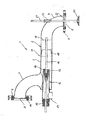
- the device according to the invention is illustrated in more detail using an exemplary embodiment. It shows the device 1 for the ventilation of water in a longitudinal section.
- the device 1 has a mixing tube 2 with a straight section 3 and a curved section 4 adjoining it in the flow direction, which terminates in an outlet opening 5.
- the outlet opening 5 is surrounded by a flange 6, via which the outlet opening 5 can be connected, for example, to the opening of a tank.
- a straight feed tube 12 that terminates in the straight section 3 of the mixing tube 2 downstream of the mouth of the air feed section 7 into the mixing tube 2 in an orifice 13.
- Mixing tube 2 and feed tube 12 have a constant, circular cross-section.
- the feed tube 12 extends coaxially to the longitudinal axis of the straight section 3 of the mixing tube 2.
- the feed tube 12 has a right-angled nozzle 14, via which the feed tube 12 can be connected to a water supply, which are provided with a water pump for pressure build-up can.
- the protruding from the mixing tube 2 end of the feed tube 12 is closed with a seal 15.
- the feed tube 12 and the straight section 3 of the mixing tube 2 passes through an adjusting rod 16 in both coaxial arrangement.
- the adjusting rod 16 is guided axially displaceably at one end in the seal 15 and at the other end in a bearing star 17.
- the bearing star 17 is connected to the inside of the mixing tube 2. Outside the feed tube 12, an adjusting device not shown here is provided, via which the adjusting rod 16 can be moved axially, be it by hand or by motor.
- a cone body 18 On the adjusting rod 16 sits in the region of the mouth opening 13, a cone body 18 whose diameter increases in the downstream direction. He partially protrudes from the feed tube 12 out. Depending on the axial position of the adjusting rod 16 and thus of the cone body 18 is formed between the inner edge of the mouth opening 13 and the shell of the cone body 18, a more or less large annular gap. It is the greater, the more the cone body 18 is adjusted in the downstream direction.
- a conical diaphragm 19 is arranged, which is connected at the upstream end with the inside of the mixing tube 2 and in the downstream direction reduces the cross-section of the mixing tube 2 in a cone shape. Behind the conical diaphragm 19, the cross section corresponds in turn to that of the mixing tube 2.
- baffle plate 20 Associated with the outlet opening 5 of the mixing tube 2 is a baffle plate 20, which is formed in the shape of a cone with a diameter which enlarges in the flow direction. It is attached to the protruding out of the outlet opening 5 end of an adjustment rod 21 which passes through the outlet opening 5 and there in a bearing star 22 axially displaceable and coaxial with the exit axis of the outlet opening 5 is guided. At the top there passes through the adjusting rod 21, the bent portion 4 of the mixing tube 2 in a sealing bushing 23. At the end projecting there is - as in the adjusting rod 16 - an adjustment provided over the distance between the outlet opening 5 and baffle plate 20 by axial displacement of the adjusting rod 21 can be adjusted.
- the device 1 shown operates in operation as follows. Via the nozzle 14, water which is possibly produced with a pump is supplied to the feed pipe 12. In the area of the conical body 18, the water is forced outwards and enters the mixing tube 2 in the form of a fan-shaped annular jet via the annular gap formed between the mouth opening 13 and the conical body 18. This is via the air inlet opening 8 and the Air supply section 7 air sucked in, which mixes intensively with the emerging from the feed tube 12, fanned water jet. This is supported by the conical diaphragm 19, which causes an acceleration of the water-air mixture. The mixture then enters the bent portion 4 of the mixing tube 2 and flows through the outlet opening 5, for example in a tank. The mixture bounces on the baffle plate 20 and is thereby diversified wide, causing a re-ventilation of the water is effected.
Landscapes
- Chemical & Material Sciences (AREA)
- Chemical Kinetics & Catalysis (AREA)
- Accessories For Mixers (AREA)
Applications Claiming Priority (2)
| Application Number | Priority Date | Filing Date | Title |
|---|---|---|---|
| DE102008012725A DE102008012725A1 (de) | 2008-03-05 | 2008-03-05 | Vorrichtung zur Begasung von Flüssigkeiten |
| EP09716818.1A EP2247373B1 (de) | 2008-03-05 | 2009-02-20 | Verfahren und verwendung einer vorrichtung zur belüftung von wasser |
Related Parent Applications (1)
| Application Number | Title | Priority Date | Filing Date |
|---|---|---|---|
| EP09716818.1 Division | 2009-02-20 |
Publications (1)
| Publication Number | Publication Date |
|---|---|
| EP2594331A1 true EP2594331A1 (de) | 2013-05-22 |
Family
ID=40527937
Family Applications (2)
| Application Number | Title | Priority Date | Filing Date |
|---|---|---|---|
| EP13154877.8A Withdrawn EP2594331A1 (de) | 2008-03-05 | 2009-02-20 | Verfahren und Vorrichtung zur Begasung von Flüssigkeiten |
| EP09716818.1A Active EP2247373B1 (de) | 2008-03-05 | 2009-02-20 | Verfahren und verwendung einer vorrichtung zur belüftung von wasser |
Family Applications After (1)
| Application Number | Title | Priority Date | Filing Date |
|---|---|---|---|
| EP09716818.1A Active EP2247373B1 (de) | 2008-03-05 | 2009-02-20 | Verfahren und verwendung einer vorrichtung zur belüftung von wasser |
Country Status (10)
| Country | Link |
|---|---|
| US (1) | US8876363B2 (pt) |
| EP (2) | EP2594331A1 (pt) |
| CN (2) | CN101970092A (pt) |
| BR (1) | BRPI0909777A2 (pt) |
| CA (1) | CA2716445A1 (pt) |
| DE (1) | DE102008012725A1 (pt) |
| ES (1) | ES2459879T3 (pt) |
| MX (1) | MX2010009760A (pt) |
| RU (1) | RU2503488C2 (pt) |
| WO (1) | WO2009109299A1 (pt) |
Families Citing this family (5)
| Publication number | Priority date | Publication date | Assignee | Title |
|---|---|---|---|---|
| US10387920B2 (en) * | 2003-12-23 | 2019-08-20 | Roku, Inc. | System and method for offering and billing advertisement opportunities |
| FR3084843B1 (fr) | 2018-08-10 | 2022-11-25 | Starklab | Dispositif de mise en contact d'un flux gazeux et d'un flux de liquide |
| DE102019111122A1 (de) * | 2019-04-30 | 2020-11-05 | Voith Patent Gmbh | Injektordüse |
| CN113560060A (zh) * | 2021-08-23 | 2021-10-29 | 上海纯元环保科技有限公司 | 一种氢水灌溉喷头 |
| CN113856505B (zh) * | 2021-10-14 | 2024-07-23 | 哈维(上海)环境科技有限公司 | 一种采用富氧溶液投加系统投加高浓度富氧溶液的方法 |
Citations (13)
| Publication number | Priority date | Publication date | Assignee | Title |
|---|---|---|---|---|
| US743528A (en) | 1902-09-02 | 1903-11-10 | Joseph Le Reau Dit L Heureux | Apparatus for flushing and ventilating urinals. |
| US2591134A (en) | 1948-03-15 | 1952-04-01 | Svend A Canariis | Method of and an apparatus for the aeration of liquids |
| DE1751255A1 (de) * | 1968-04-27 | 1971-06-09 | Koerting Oel Gasfeuerung | Brenner fuer gasfoermige Brennstoffe |
| US3770208A (en) * | 1970-11-23 | 1973-11-06 | Ethyl Corp | Mixing nozzle |
| US4282172A (en) * | 1980-09-11 | 1981-08-04 | Howe-Baker Engineers, Inc. | Gas to liquid diffuser |
| US4375185A (en) | 1981-05-26 | 1983-03-01 | Fmc Corporation | Milk sterilizing apparatus |
| CH642563A5 (en) | 1982-09-09 | 1984-04-30 | Buchs Utb Umwelttechnik Ag | Method for introducing air bubbles or oxygen bubbles into sewage sludge, and appliance for implementing the method |
| EP0486933A2 (de) * | 1990-11-19 | 1992-05-27 | Miteco AG | Vorrichtung zum Lösen von Feststoff-Schüttgut in einer Flüssigkeit |
| US5372283A (en) | 1992-03-17 | 1994-12-13 | Nordson Corporation | Two-component dispensing system |
| DE4433744A1 (de) | 1994-09-21 | 1996-03-28 | Weizdoerfer Anton & Co Gmbh | Vorrichtung zur Erzeugung flüssiger Systeme, insbesondere von Emulsionen, Suspensionen od. dgl. in einem hydrodynamischen Kavitationsfeld |
| DE19707165A1 (de) * | 1997-02-22 | 1998-08-27 | Gelhard Volker Dipl Ing Dipl W | Vorrichtung und Verfahren zum Vermischen eines ersten Fluids mit einem zweiten Fluid |
| US5992529A (en) * | 1996-12-16 | 1999-11-30 | Williams Fire & Hazard Control, Inc. | Mixing passage in a foam fire fighting nozzle |
| DE102005037026A1 (de) | 2005-08-05 | 2007-02-15 | Wagner, Manfred | Kavitationsmischer |
Family Cites Families (30)
| Publication number | Priority date | Publication date | Assignee | Title |
|---|---|---|---|---|
| US3123127A (en) * | 1964-03-03 | Flat radiant-wall furnace and gas burner | ||
| US724053A (en) * | 1901-09-28 | 1903-03-31 | Richard Franklin Schroeder | Oil-burner. |
| US823836A (en) * | 1905-04-14 | 1906-06-19 | Empire Machine Co | Gas-burner. |
| US1474677A (en) * | 1920-11-26 | 1923-11-20 | Walter J Krause | Hydrocarbon burner |
| US1643967A (en) * | 1923-04-12 | 1927-10-04 | Sta Kleen Burner Company | Low-pressure oil burner |
| US1563246A (en) * | 1924-05-26 | 1925-11-24 | Zulver Cornelis | Liquid-fuel burner or atomizer |
| US1779647A (en) * | 1927-11-23 | 1930-10-28 | Int Comb Eng Corp | Burner |
| US2527689A (en) * | 1946-12-11 | 1950-10-31 | Petrolite Corp | Apparatus for mixing |
| US2746711A (en) * | 1952-04-10 | 1956-05-22 | Allis Chalmers Mfg Co | Valve actuating means |
| US2908477A (en) * | 1954-10-11 | 1959-10-13 | Sulzer Ag | Valve mechanism |
| US3133836A (en) * | 1962-03-26 | 1964-05-19 | Penick & Ford Ltd | Method of treating starch with steam |
| US3347267A (en) * | 1963-05-15 | 1967-10-17 | Du Pont | Spray valve for injecting a reactant liquid into a stream of another reactant liquid |
| US3227425A (en) * | 1963-05-27 | 1966-01-04 | Heinz Co H J | Kettle outlet and valve assembly |
| US3547409A (en) * | 1968-05-23 | 1970-12-15 | Jacuzzi Bros Inc | Assembly for producing detergent foam |
| US3677522A (en) * | 1970-12-02 | 1972-07-18 | Dow Chemical Co | Feeder stream mixer |
| US3721387A (en) * | 1971-06-02 | 1973-03-20 | United Aircraft Corp | Ejector with variable mixing section and primary nozzle areas |
| US3782884A (en) * | 1972-05-09 | 1974-01-01 | Standard Oil Co | Acid gas burner |
| US3988002A (en) * | 1972-07-10 | 1976-10-26 | United Technologies Corporation | In-line balance valves |
| US3845904A (en) * | 1973-12-07 | 1974-11-05 | Src Lab | Variable flow two stage nozzle |
| US4443182A (en) * | 1981-11-10 | 1984-04-17 | Hauck Manufacturing Company | Burner and method |
| US4631004A (en) * | 1982-07-13 | 1986-12-23 | The Garrett Corporation | Jet pump having pressure responsive motive fluid control valve |
| SU1600072A1 (ru) * | 1987-04-06 | 1997-08-20 | Л.И. Пищенко | Кавитационный реактор |
| RU1772086C (ru) * | 1991-01-14 | 1992-10-30 | Томский инженерно-строительный институт | Устройство дл аэрации сточных вод |
| US5240409A (en) * | 1992-04-10 | 1993-08-31 | Institute Of Gas Technology | Premixed fuel/air burners |
| US5622655A (en) * | 1995-04-10 | 1997-04-22 | Hydro-Thermal Corporation | Sanitary direct contact steam injection heater and method |
| US6203186B1 (en) * | 1999-09-13 | 2001-03-20 | Luis R. Cruz | Spherical eductor atomizer |
| US6422735B1 (en) * | 1999-09-20 | 2002-07-23 | John Stewart Lang | Hydraulic jet flash mixer with open injection port in the flow deflector |
| DE10009326A1 (de) * | 2000-02-28 | 2001-08-30 | Rs Kavitationstechnik | Kavitationsmischer |
| US6701715B2 (en) * | 2002-05-02 | 2004-03-09 | Honeywell International, Inc. | Variable geometry ejector for a bleed air system using integral ejector exit pressure feedback |
| NL1028460C2 (nl) * | 2005-03-04 | 2006-09-06 | Sara Lee De Nv | Inrichting voor het bereiden en afgeven van al dan niet althans gedeeltelijk opgeschuimde dranken. |
-
2008
- 2008-03-05 DE DE102008012725A patent/DE102008012725A1/de not_active Ceased
-
2009
- 2009-02-20 WO PCT/EP2009/001223 patent/WO2009109299A1/de not_active Ceased
- 2009-02-20 EP EP13154877.8A patent/EP2594331A1/de not_active Withdrawn
- 2009-02-20 CA CA2716445A patent/CA2716445A1/en not_active Abandoned
- 2009-02-20 BR BRPI0909777A patent/BRPI0909777A2/pt not_active IP Right Cessation
- 2009-02-20 CN CN2009801078015A patent/CN101970092A/zh active Pending
- 2009-02-20 ES ES09716818.1T patent/ES2459879T3/es active Active
- 2009-02-20 US US12/921,191 patent/US8876363B2/en active Active
- 2009-02-20 CN CN201710368820.XA patent/CN107261883B/zh active Active
- 2009-02-20 MX MX2010009760A patent/MX2010009760A/es active IP Right Grant
- 2009-02-20 EP EP09716818.1A patent/EP2247373B1/de active Active
- 2009-02-20 RU RU2010140586/05A patent/RU2503488C2/ru not_active IP Right Cessation
Patent Citations (13)
| Publication number | Priority date | Publication date | Assignee | Title |
|---|---|---|---|---|
| US743528A (en) | 1902-09-02 | 1903-11-10 | Joseph Le Reau Dit L Heureux | Apparatus for flushing and ventilating urinals. |
| US2591134A (en) | 1948-03-15 | 1952-04-01 | Svend A Canariis | Method of and an apparatus for the aeration of liquids |
| DE1751255A1 (de) * | 1968-04-27 | 1971-06-09 | Koerting Oel Gasfeuerung | Brenner fuer gasfoermige Brennstoffe |
| US3770208A (en) * | 1970-11-23 | 1973-11-06 | Ethyl Corp | Mixing nozzle |
| US4282172A (en) * | 1980-09-11 | 1981-08-04 | Howe-Baker Engineers, Inc. | Gas to liquid diffuser |
| US4375185A (en) | 1981-05-26 | 1983-03-01 | Fmc Corporation | Milk sterilizing apparatus |
| CH642563A5 (en) | 1982-09-09 | 1984-04-30 | Buchs Utb Umwelttechnik Ag | Method for introducing air bubbles or oxygen bubbles into sewage sludge, and appliance for implementing the method |
| EP0486933A2 (de) * | 1990-11-19 | 1992-05-27 | Miteco AG | Vorrichtung zum Lösen von Feststoff-Schüttgut in einer Flüssigkeit |
| US5372283A (en) | 1992-03-17 | 1994-12-13 | Nordson Corporation | Two-component dispensing system |
| DE4433744A1 (de) | 1994-09-21 | 1996-03-28 | Weizdoerfer Anton & Co Gmbh | Vorrichtung zur Erzeugung flüssiger Systeme, insbesondere von Emulsionen, Suspensionen od. dgl. in einem hydrodynamischen Kavitationsfeld |
| US5992529A (en) * | 1996-12-16 | 1999-11-30 | Williams Fire & Hazard Control, Inc. | Mixing passage in a foam fire fighting nozzle |
| DE19707165A1 (de) * | 1997-02-22 | 1998-08-27 | Gelhard Volker Dipl Ing Dipl W | Vorrichtung und Verfahren zum Vermischen eines ersten Fluids mit einem zweiten Fluid |
| DE102005037026A1 (de) | 2005-08-05 | 2007-02-15 | Wagner, Manfred | Kavitationsmischer |
Also Published As
| Publication number | Publication date |
|---|---|
| CA2716445A1 (en) | 2009-09-11 |
| WO2009109299A1 (de) | 2009-09-11 |
| EP2247373B1 (de) | 2014-01-01 |
| MX2010009760A (es) | 2010-11-25 |
| BRPI0909777A2 (pt) | 2015-10-06 |
| US20110007599A1 (en) | 2011-01-13 |
| CN107261883B (zh) | 2020-01-07 |
| HK1245707A1 (zh) | 2018-08-31 |
| CN101970092A (zh) | 2011-02-09 |
| ES2459879T3 (es) | 2014-05-12 |
| RU2010140586A (ru) | 2012-04-10 |
| CN107261883A (zh) | 2017-10-20 |
| US8876363B2 (en) | 2014-11-04 |
| EP2247373A1 (de) | 2010-11-10 |
| DE102008012725A1 (de) | 2009-09-24 |
| RU2503488C2 (ru) | 2014-01-10 |
Similar Documents
| Publication | Publication Date | Title |
|---|---|---|
| EP2798987B1 (de) | Verfahren und Vorrichtung zur Erzeugung von Milchprodukten, insbesondere Milchschaum | |
| DE2634496C2 (de) | Injektor zur Begasung einer Flüssigkeit | |
| DE69329061T2 (de) | Vorrichtung zur lösung eines gases in bzw zur mischung einer flüssigkeit | |
| DE2252218C2 (de) | Vorrichtung zum Zerstäuben eines Fluids | |
| DE112012005017B4 (de) | Vorrichtung zum Steuern einer Fluid-Strömung in einem Notfall-Waschsystem, Vorrichtung zum Steuern einer Fluid-Strömung und Waschsystem zum Liefern einer Fluid-Strömung | |
| EP0550510B1 (de) | Belüftungsdüse zum belüften von organische substanzen enthaltenden flüssigkeiten | |
| EP2247373B1 (de) | Verfahren und verwendung einer vorrichtung zur belüftung von wasser | |
| EP4323094B1 (de) | Vorrichtung und verfahren zum dispergieren von gasen in flüssigkeiten | |
| DE4016727C2 (pt) | ||
| EP1689940B1 (de) | Durchflussmengenbegrenzer | |
| DE2231141A1 (de) | Vorrichtung zur erzeugung von reinigungsschaum | |
| EP1293255A2 (de) | Verfahren und Vorrichtung zur Abtrennung von Störstoffen aus Suspensionen durch Flotation | |
| DE2434935A1 (de) | Verfahren und vorrichtung zum belueften einer fluessigkeit | |
| WO2008116530A1 (de) | Vorrichtung zur kontinuierlichen anreicherung von gasen in wasser | |
| WO2009086822A2 (de) | Verfahren und zugehörige vorrichtung zum drucklosen oder nahezu drucklosen eintragen von schaum in einen unter druck stehenden materialstrom | |
| DE2757522B1 (de) | Rund- oder Ringstrahlduese zum Erzeugen und Abstrahlen eines Nebels oder Aerosols zur Beschichtung von Gegenstaenden | |
| WO2007095770A1 (de) | Vorrichtung zum wärmen und aufschäumen von flüssigkeiten | |
| DE102010023631B4 (de) | Statischer Mischer und Mischverfahren | |
| CH201450A (de) | Luftschaumerzeuger. | |
| CH702076A2 (de) | Injektionsvorrichtung und Verfahren zur Reinigung von Belüfterkanälen einer Kläranlage. | |
| DE102005004341A1 (de) | Vorrichtung zur Zerstäubung einer unter Druck stehenden Flüssigkeit mittels Druckluft | |
| EP0264689A1 (de) | Vorrichtung zum Erzeugen von Schaum | |
| CH674160A5 (en) | Water forming porous concrete entrains foaming agent - from container supporting spray unit and sieve | |
| DE102023135644A1 (de) | Vorrichtung und Verfahren zur Karbonisierung von Flüssigkeiten | |
| DE4446000C2 (de) | Vorrichtung zum Mischen zweier strömender Fluide, insbesondere zum Belüften von Würze für die Bierherstellung |
Legal Events
| Date | Code | Title | Description |
|---|---|---|---|
| PUAI | Public reference made under article 153(3) epc to a published international application that has entered the european phase |
Free format text: ORIGINAL CODE: 0009012 |
|
| AC | Divisional application: reference to earlier application |
Ref document number: 2247373 Country of ref document: EP Kind code of ref document: P |
|
| AK | Designated contracting states |
Kind code of ref document: A1 Designated state(s): AT BE BG CH CY CZ DE DK EE ES FI FR GB GR HR HU IE IS IT LI LT LU LV MC MK MT NL NO PL PT RO SE SI SK TR |
|
| 17P | Request for examination filed |
Effective date: 20131122 |
|
| RBV | Designated contracting states (corrected) |
Designated state(s): AT BE BG CH CY CZ DE DK EE ES FI FR GB GR HR HU IE IS IT LI LT LU LV MC MK MT NL NO PL PT RO SE SI SK TR |
|
| 17Q | First examination report despatched |
Effective date: 20140221 |
|
| STAA | Information on the status of an ep patent application or granted ep patent |
Free format text: STATUS: THE APPLICATION IS DEEMED TO BE WITHDRAWN |
|
| 18D | Application deemed to be withdrawn |
Effective date: 20140904 |