EP2594355B1 - Machine et méthode de coupage et de soudage avec un dispositif de positionnement de deux extrémités de matériaux l'une contre l'autre - Google Patents
Machine et méthode de coupage et de soudage avec un dispositif de positionnement de deux extrémités de matériaux l'une contre l'autre Download PDFInfo
- Publication number
- EP2594355B1 EP2594355B1 EP11306506.4A EP11306506A EP2594355B1 EP 2594355 B1 EP2594355 B1 EP 2594355B1 EP 11306506 A EP11306506 A EP 11306506A EP 2594355 B1 EP2594355 B1 EP 2594355B1
- Authority
- EP
- European Patent Office
- Prior art keywords
- carrier
- adjusting member
- cutting
- actuator
- carriers
- Prior art date
- Legal status (The legal status is an assumption and is not a legal conclusion. Google has not performed a legal analysis and makes no representation as to the accuracy of the status listed.)
- Active
Links
Images


Classifications
-
- B—PERFORMING OPERATIONS; TRANSPORTING
- B23—MACHINE TOOLS; METAL-WORKING NOT OTHERWISE PROVIDED FOR
- B23K—SOLDERING OR UNSOLDERING; WELDING; CLADDING OR PLATING BY SOLDERING OR WELDING; CUTTING BY APPLYING HEAT LOCALLY, e.g. FLAME CUTTING; WORKING BY LASER BEAM
- B23K31/00—Processes relevant to this subclass, specially adapted for particular articles or purposes, but not covered by any single one of main groups B23K1/00 - B23K28/00
- B23K31/02—Processes relevant to this subclass, specially adapted for particular articles or purposes, but not covered by any single one of main groups B23K1/00 - B23K28/00 relating to soldering or welding
-
- B—PERFORMING OPERATIONS; TRANSPORTING
- B21—MECHANICAL METAL-WORKING WITHOUT ESSENTIALLY REMOVING MATERIAL; PUNCHING METAL
- B21C—MANUFACTURE OF METAL SHEETS, WIRE, RODS, TUBES, PROFILES OR LIKE SEMI-MANUFACTURED PRODUCTS OTHERWISE THAN BY ROLLING; AUXILIARY OPERATIONS USED IN CONNECTION WITH METAL-WORKING WITHOUT ESSENTIALLY REMOVING MATERIAL
- B21C47/00—Winding-up, coiling or winding-off metal wire, metal band or other flexible metal material characterised by features relevant to metal processing only
- B21C47/24—Transferring coils to or from winding apparatus or to or from operative position therein; Preventing uncoiling during transfer
- B21C47/247—Joining wire or band ends
-
- B—PERFORMING OPERATIONS; TRANSPORTING
- B23—MACHINE TOOLS; METAL-WORKING NOT OTHERWISE PROVIDED FOR
- B23K—SOLDERING OR UNSOLDERING; WELDING; CLADDING OR PLATING BY SOLDERING OR WELDING; CUTTING BY APPLYING HEAT LOCALLY, e.g. FLAME CUTTING; WORKING BY LASER BEAM
- B23K26/00—Working by laser beam, e.g. welding, cutting or boring
- B23K26/20—Bonding
- B23K26/21—Bonding by welding
- B23K26/24—Seam welding
- B23K26/26—Seam welding of rectilinear seams
-
- B—PERFORMING OPERATIONS; TRANSPORTING
- B23—MACHINE TOOLS; METAL-WORKING NOT OTHERWISE PROVIDED FOR
- B23K—SOLDERING OR UNSOLDERING; WELDING; CLADDING OR PLATING BY SOLDERING OR WELDING; CUTTING BY APPLYING HEAT LOCALLY, e.g. FLAME CUTTING; WORKING BY LASER BEAM
- B23K37/00—Auxiliary devices or processes, not specially adapted for a procedure covered by only one of the other main groups of this subclass
- B23K37/04—Auxiliary devices or processes, not specially adapted for a procedure covered by only one of the other main groups of this subclass for holding or positioning work
- B23K37/0408—Auxiliary devices or processes, not specially adapted for a procedure covered by only one of the other main groups of this subclass for holding or positioning work for planar work
-
- B—PERFORMING OPERATIONS; TRANSPORTING
- B23—MACHINE TOOLS; METAL-WORKING NOT OTHERWISE PROVIDED FOR
- B23K—SOLDERING OR UNSOLDERING; WELDING; CLADDING OR PLATING BY SOLDERING OR WELDING; CUTTING BY APPLYING HEAT LOCALLY, e.g. FLAME CUTTING; WORKING BY LASER BEAM
- B23K37/00—Auxiliary devices or processes, not specially adapted for a procedure covered by only one of the other main groups of this subclass
- B23K37/04—Auxiliary devices or processes, not specially adapted for a procedure covered by only one of the other main groups of this subclass for holding or positioning work
- B23K37/047—Auxiliary devices or processes, not specially adapted for a procedure covered by only one of the other main groups of this subclass for holding or positioning work moving work to adjust its position between soldering, welding or cutting steps
-
- B—PERFORMING OPERATIONS; TRANSPORTING
- B23—MACHINE TOOLS; METAL-WORKING NOT OTHERWISE PROVIDED FOR
- B23K—SOLDERING OR UNSOLDERING; WELDING; CLADDING OR PLATING BY SOLDERING OR WELDING; CUTTING BY APPLYING HEAT LOCALLY, e.g. FLAME CUTTING; WORKING BY LASER BEAM
- B23K9/00—Arc welding or cutting
- B23K9/02—Seam welding; Backing means; Inserts
- B23K9/025—Seam welding; Backing means; Inserts for rectilinear seams
-
- B—PERFORMING OPERATIONS; TRANSPORTING
- B23—MACHINE TOOLS; METAL-WORKING NOT OTHERWISE PROVIDED FOR
- B23K—SOLDERING OR UNSOLDERING; WELDING; CLADDING OR PLATING BY SOLDERING OR WELDING; CUTTING BY APPLYING HEAT LOCALLY, e.g. FLAME CUTTING; WORKING BY LASER BEAM
- B23K2101/00—Articles made by soldering, welding or cutting
- B23K2101/16—Bands or sheets of indefinite length
-
- B—PERFORMING OPERATIONS; TRANSPORTING
- B23—MACHINE TOOLS; METAL-WORKING NOT OTHERWISE PROVIDED FOR
- B23K—SOLDERING OR UNSOLDERING; WELDING; CLADDING OR PLATING BY SOLDERING OR WELDING; CUTTING BY APPLYING HEAT LOCALLY, e.g. FLAME CUTTING; WORKING BY LASER BEAM
- B23K2101/00—Articles made by soldering, welding or cutting
- B23K2101/18—Sheet panels
Definitions
- the present invention relates to a device for holding and connecting two material ends according to the preamble of claim 1, and a method for producing along their opposite end faces of welded material ends according to the preamble of claim 6.
- the US 5,456,405 describes the welding of metal strips in the continuous production of a metal tube by cutting the facing ends of the metal strips at an angle to the longitudinal axis and with an inclination against the cross-sectional plane, welding the opposite ends and removing protruding material in the weld, wherein the weld during welding is extended by laterally attached to the sheet metal strips sheet pieces over the longitudinal edges addition.
- the US 3,915,368 describes a carrier on which a first actuator and a second actuator movable thereon for positioning a metal strip are arranged.
- the actuators are used to push the held metal band against closed jaws, cut them with scissors and then advance through the open jaws.
- the WO 2010/052339 A1 describes for the positioning of metal strips only driven rollers with position sensors for the workpiece.
- the object of the invention is to provide an alternative device and an alternative method for connecting end faces of two sheet-metal strips that can be implemented therewith.
- the invention solves the problem with a device and a method according to the Claims 1 and 12, with an apparatus and a method for positionally accurate positioning of two opposite material ends against each other with a predetermined force.
- the device according to the invention allows a precise positioning of two opposing material ends with their end faces against each other, wherein the force with which the end faces are moved against each other or are arranged against each other, can be predetermined.
- the device has two carriers, each with a fixing device for each material end, wherein at least a first of the two carriers is displaceably guided against the second of the carrier and at least the first carrier has a first actuator and a second actuator connected to the first actuator, the form a drive, with which the first carrier is movable against the second carrier.
- a sliding element, a connecting element and the carrier attached thereto form a rigid frame which is preferably connected to the loose end of a first actuator, this loose end being fastened, for example, to the sliding element.
- at least the first carrier is guided on guide rails or guide rods.
- at least one of the carriers can have a position sensor, which is preferably connected to a control unit for the first and / or second actuator.
- the position sensor is disposed between an adjustable part of the second actuator, which is, for example, its part connected to the loose end or its fixed end, and the sliding element or the base frame.
- the sensor for determining the positioning of the parts of the second actuator is set up to each other, so that for example the position of the adjustable part of the second actuator can be controlled under control of the sensor to a controlled positioning of the parts of the second actuator to each other and / or to allow a controlled actuation of the second actuator.
- the device may comprise a force sensor which is adapted to measure the force acting between the carriers, wherein preferably the force sensor is connected to a control unit.
- the control unit is set up to control, in particular to move, the first and / or second actuator on the basis of the signal of a position sensor and / or a force sensor until, by means of a sensor, a predetermined position of a carrier or the carrier relative to one another and / or to a predetermined force between the carriers is determined.
- the position of the carrier, in which the opposite material ends are arranged against each other and are welded, is also referred to as welding position.
- a second actuator which has a sliding wedge, preferably has as a sensor for determining the position of the carrier, a sensor which determines the position of the sliding wedge.
- the device comprises a cutter, e.g. is movable between the carriers and cuts in the process material ends in mating, in particular parallel end faces.
- the position in which the carriers are spaced to position the cutter at the material ends, and in particular to move the cutter between the carriers, is also referred to as the cutting position.
- the device of the device e.g. for performing method steps
- the corresponding steps of the method and the description of method steps describes the device of the device for these method steps.
- the device and the method for connecting two material ends by welding together is particularly suitable for use for welding the end faces of thin sheets, for example, for sheets with a thickness of ⁇ 1 mm, for example, of ⁇ 0.5, more preferably of ⁇ 0.3 mm Thickness, in particular with a thickness of ⁇ 0.2 mm, ⁇ 0.1 mm or ⁇ 0.05 mm.
- the interaction of the first and second actuator leads by controlling the first and / or the second actuator to a positionally accurate positioning of the end faces of the material ends against each other, in particular until a predetermined distance between the material ends or between the first and the second carrier, preferably until reaching a predetermined force between carriers or between the fixed to the carriers, opposite material ends.
- the end faces are parallel to each other.
- the distance between the carriers and / or the force acting between the carriers is preferably measured with a distance sensor or a force sensor, wherein a control unit controls the first and / or the second actuator as a function of the signal of the sensor.
- the second carrier may be fixed in place, or guided displaceably mounted against the first carrier, in particular with a drive, the first actuator or a comprises first actuator and a second actuator connected thereto or consists thereof.
- the first and second carrier may be mutually displaceable and have an identically constructed drive. Therefore, the description of the drive with or from the first and associated second actuator with respect to the first carrier also refers to the formation of the second carrier in its embodiments with a drive having a first actuator or a first and a second actuator connected thereto or consists of.
- the first actuator serves to move the first carrier relative to the second carrier, e.g. towards the second carrier to or from the second carrier away for coarse positioning of the first carrier to the second carrier, while the second actuator of the more accurate positioning of the first carrier relative to the second carrier is used.
- the first actuator and / or the second actuator is independently, e.g. a hydraulic or pneumatic actuator cylinder, a first spindle drive, rack drive, cam drive, cam or eccentric, a powered toggle, a driven linear axis, a gear drive or toothed belt drive.
- the second actuator may e.g. a spindle drive or a wedge drive with two wedges, one of which is displaceable against the other at an angle to the direction of movement of the first carrier, in particular perpendicular to the first carrier.
- the first carrier may be displaceable relative to a base frame along a guide.
- the second carrier may be fixedly connected to the base frame, by means of a first actuator, which is arranged between the base frame and the second carrier, guided against the first carrier to be displaceable, or corresponding to the first carrier by means of a first actuator, which carries a second actuator against the base frame slidably guided against the first carrier.
- the carriers each have a fixing device for fixing in each case a portion of a material, wherein preferably the end of the material projects via a carrier in the direction of the other carrier.
- each carrier has a flat surface against which the material is arranged. This flat surface may optionally be part of the fixing device.
- the fixing device has a further, against the flat surface of a carrier movable flat surface, and forms on or with the carrier two spaced and mutually movable flat surfaces, between which material, in particular a metal strip can be fixed.
- each carrier has a stop which is parallel to the longitudinal axis of the guide, along which the first carrier is displaceable, is arranged at an acute angle to the longitudinal axis of the guide and projects beyond a surface portion of the carrier on which a material is arranged.
- the stops of each carrier are preferably parallel or at an acute angle to each other, e.g. 0 ° to 45 °, preferably to 30 ° or to 18 °, more preferably to 15 °, and the end faces are, e.g. by cutting, arranged at this angle to its cross section.
- the stops are arranged opposite one another with respect to the longitudinal axis of the guide, along which the first carrier is displaceable, so that the materials bear against the stops with respect to their longitudinal axis at opposite longitudinal edges.
- the stops are arranged on a common side with respect to the longitudinal axis of the guide, along which the first carrier is displaceable, so that the materials abut the stops with respect to their longitudinal axis of the same longitudinal edge.
- the stops in particular if they are arranged at an angle to the longitudinal axis of the guide, along which the first carrier is displaceable, arranged with offset from each other. Such an offset of the stops is in particular designed so that the end faces of the material ends are arranged to fit against each other after cutting by moving the carrier.
- the offset of the stops causes a compensation of the offset of the material ends, which results from a distance of the carrier when the material ends protrude beyond the carrier.
- the offset of the stops which is determined by the cutting width of a cutter used for cutting, the distance of the stops to the knife edge or the extent to which the cut material ends the support and possibly the cutting angle, for example, then adjusted appropriately when the intersections the degrees passing through the stops lie with the respective adjacent edge of the cutting device at a level which is parallel to the direction of movement in which the first carrier is displaceably guided against the second carrier.
- the offset is suitable if the intersections of the degrees passing through the stops are arranged on a plane perpendicular to the cut edge or perpendicular to the end faces.
- the first actuator is connected according to the invention with its fixed end to the base frame and with its loose end to the first carrier, so that the first carrier by means of the first actuator relative to the base frame is movable.
- the second carrier is arranged in the direction of movement of the first actuator, e.g. fixed to the base frame or by means of a drive with a first or with a first and a second actuator relative to the base frame movable.
- the first actuator and the second actuator counteract each other by the carrier, whose drive is formed by the first and the second actuator, has a sliding element or is connected to a sliding element which is connected to the loose end of the first actuator and the Losende the second actuator is connected, in particular between the loose end of the first actuator and the loose end of the second actuator is fixed, while the fixed end of the first actuator and the fixed end of the second actuator are fixed to the common base frame.
- the second actuator forms an abutment surface for the sliding element, which limits the movement of the sliding element in the direction of the second carrier.
- the second actuator has at least two parts, one of which forms the loose part connected to the loose end and the other forms the fixed part connected to the fixed part, which act against each other exclusively by frictional connection.
- the sliding element and the associated first carrier are moved. Actuation of the first actuator in one direction causes movement of the sliding member away from the stationary end of the second actuator, e.g. in an operating condition in which the carriers are remote from each other, or when actuated in an opposite direction, a movement of the sliding element towards the fixed end of the second actuator until the release portion of the second actuator abuts against the fixed portion of the second actuator, e.g. in an operating condition in which the carriers are positioned to a predetermined minimum distance.
- An example of a second actuator having at least two parts, namely a loose part and a fixed part, which are freely displaceable against each other until the frictional connection, is a wedge adjustment with two wedges, one of which with the Losende and the other with the Fixed end is connected, which are displaceable relative to each other along the wedge surfaces.
- Another example of a second actuator having two mutually displaceable parts, one of which is connected to the loose end and the other with the fixed end, is a co-operating with an abutment screw whose one end abuts against the abutment surface and the other end is guided in a thread.
- the abutment surface forms one part and the adjusting screw guided in the thread forms the other part, which are removable from each other, since the adjusting screw is not engaged with the abutment surface.
- a sensor is connected to the part of the second actuator, which is displaceable relative to the other part, for example with that of the wedges, which is displaceable relative to the base frame or with the adjusting screw.
- the second actuator may be preset in a certain position in which the distance between the loose end and fixed end of the second actuator is fixed, since the movement of the first carrier in the direction of the second carrier by the second actuator by the frictional connection or is limited by contacting its two parts against each other.
- the fixed end of the second actuator is connected to the base frame, and the loose end of the second actuator is connected to the loose end of the first actuator, preferably a sliding element, which is connected to the first carrier, with the two loose ends of first and second actuator is connected.
- the second actuator preferably comprises two parts, one of which is connected to the fixed end and the other with the loose end, wherein both parts are separable from each other and separated by moving the first carrier in the direction of the fixed end of the first actuator, wherein Preferably, in this position, the over the carrier projecting material ends are cut, and then by actuation of the first actuator connected to the loose end of the second actuator part of the second actuator is moved against its connected to the fixed part part until first and second part abut each other, in particular by friction, preferably in this position, the opposite end face of the first and second material end abut against each other.
- the carriers are positioned at a predetermined minimum distance from each other, in which the carrier are in welding position.
- the first carrier and / or the sliding element is generally guided by means of a first guide device, wherein preferably the first carrier and / or the sliding element is rigidly connected to the guide device.
- the device on the sliding element on two parallel to the connecting element and / or parallel to the guide acting first actuators.
- the first and / or the second actuator is controlled by a control device and the device has a sensor which measures the positioning of the parts of the second actuator, in particular the positioning of the frame relative to the movable part of the second actuator, or the position of the first carrier relative to the second carrier measures.
- the control device is to configured to control the first and / or the second actuator in response to the signal of the sensor indicating the position of the first carrier relative to the second carrier.
- the control device is adapted to move the first and / or the second actuator to a predetermined position relative to the second carrier, for example, up to a predetermined distance of the first carrier from the second carrier.
- the senor is a force sensor configured to measure the force between the first carrier and the second carrier.
- the control device is preferably arranged to control the first and / or second actuator in response to the signal of the force sensor until the first carrier against reaching a predetermined amount for the force acting between the first and the second carrier against the second carrier is moved.
- the device can be set up so that the material ends fixed on the carriers project beyond the carrier to which they are fixed, and are moved against each other in a common plane until their end faces abut one another, so that a force sensor which is set up Force between the first and the second carrier, which is determined as a measure of the force acting between the abutting faces of the material ends force and, for example is used to control the first and / or second actuator.
- the position of the second actuator of the first carrier optionally in addition the position of the first actuator and / or the second actuator of the second carrier, be set manually, in particular in a position in which abutment of the parts of the second actuator to each other , eg with adhesion of its two parts, the first carrier is in a position in which projecting beyond the carrier material ends are arranged against each other after cutting by means of the cutting device in a predetermined position and / or with a predetermined force.
- control device may be arranged to control the second actuator to a position in which the first carrier is in a position when the parts of the second actuator are in contact with each other, for example when the two parts are in force against each other projecting material ends after cutting by means of the cutter are arranged with predetermined force against each other, wherein the control means is arranged, the first carrier, optionally additionally the second carrier for movement in a spaced-apart position only by actuation of the respective first actuator to control and after fixing the materials to the carriers and cutting the material ends to control the first carrier for movement in the direction of the second carrier only by actuation of the respective first actuator.
- the apparatus preferably has a cutting device which is set up to cut, in particular cut parallel to one another, the materials fixed on the first and second supports, in particular sheet-metal strips whose material ends project beyond the support in the direction of the opposite support.
- the cutting device may comprise a laser, which is directed to the region between the first and the second carrier.
- a preferred cutting device has a cutting element which is movable adjacent to a counter knife or between two counter knives, in particular along a counter knife or between two counter knives movable, in particular linearly movable, or is pivotable.
- the apparatus is arranged to position the carriers in a cutting position in which the cutter cuts the material ends and in the e.g. the cutting device is movable between the carriers.
- the device may comprise a control device which is adapted to position the first and / or the second carrier in a predetermined cutting position and / or the device may each have an abutment surface for the first and / or have the second carrier, in the contact of the first and / or the second carrier are positioned in the cutting position.
- the device has a sealing bar which, after cutting the material ends, preferably before or after displacement of the first carrier against the second carrier, in particular up to a position in which the cut material ends abut against each other, is positioned adjacent to the plane the carrier or the materials arranged on the carriers extend.
- a sealing bar has two bearing surfaces that are aligned parallel to the plane of the beams and define therebetween a groove that is parallel to the abutting ends of the material.
- a weld bar aids in alignment of the material ends in a common plane, and preferably serves for heat dissipation adjacent to the faces of the material ends during welding.
- the device optionally has a supply device for inert gas, which opens, for example, in the groove of the sealing bar.
- the fixing device of the first and / or the second carrier may have an extension with a surface which extends approximately parallel to the carriers and / or parallel to the bearing surfaces of the sealing bar.
- the welding bar is attached to the cutting element, so that the welding bar can be positioned after moving the cutting element between the carriers for cutting the material ends by moving the cutting element, in particular positioned adjacent to the material ends.
- the welding bar is mounted opposite the welding device on the cutting element, and more preferably the welding strip is attached to the cutting element opposite its cutting edge and positionable by moving the cutting element adjacent to the plane in which the beams extend.
- the cutting device is arranged to be moved for cutting between the carriers positioned at a cutting position spaced apart, after cutting the carriers are moved to their welding position and the cutting element is moved until the sealing strip is positioned adjacent to the plane in which the carriers or the material ends fixed on the carriers extend.
- the device is arranged to space the first and / or the second carrier after cutting from one another further than they are spaced in the cutting position and then to move the cutting device between the carriers away. In this way, in particular when the cutting device has knives which rest against the cut end faces of the material ends after cutting, a mechanical load on the cut end faces is avoided.
- the fixing device of each carrier preferably has a clamping bar which has a flat clamping surface on the flat surface of the carrier on which a material is arranged.
- a clamping bar may be pivotable against the carrier and / or guided displaceably parallel to the carrier.
- a clamping bar, which is articulated pivotably against the carrier or is displaceably guided against the carrier, is preferably pivotably articulated at its first end to the carrier or displaceably mounted on the carrier.
- the clamping bar can have at its first end a first clamping drive, which spaces the clamping bar from the carrier or loads it in a clamping position against the carrier.
- the clamping bar is preferably slidably guided against the carrier at a second end which is at least the width of the material or the width of the flat surface spaced from the first end.
- the clamping bar may be engaged with, or releasably engageable with, a second clamping drive at its second end with a second clamping drive, the second clamping drive being arranged to load the clamping bar in a clamping position against the carrier.
- the first clamping drive is connected by means of a first rod to the first end of the clamping bar, wherein the first rod is guided perpendicular to the flat surface of the carrier, for example in a perpendicular to the plane of the carrier arranged bore.
- the second clamping drive is preferably engageable by means of a second bar with the second end of the clamping bar, wherein the second bar is further preferably arranged in a bore of the carrier, which is parallel to the bore in which the first bar is arranged ,
- first and second actuators are generally controlled by a control unit in response to the signal from a sensor until first and second carriers are biased against each other at a predetermined force acting between the end faces of the material ends fixed thereon or until first and second carriers enter predetermined position are moved against each other.
- the device preferably has a welding device, in particular a laser welding device or a MIG or a MAG or a TIG welding device, and the method comprises the step of welding the mutually abutting end faces of the material ends, in particular by means of MIG or MAG or TIG - or laser welding.
- a welding device in particular a laser welding device or a MIG or a MAG or a TIG welding device
- the method comprises the step of welding the mutually abutting end faces of the material ends, in particular by means of MIG or MAG or TIG - or laser welding.
- first and second actuator are each provided with the same functional elements and are mutually displaceable or mutually displaceable.
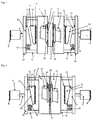
- FIG. 1 shows a plan view of a device according to the first embodiment, in which a first carrier 1 is displaceable against a second carrier 2, and on each carrier 1, 2, a material is fixed by means of a fixing device 20, the material ends 3, 4 respectively the carrier. 1 , 2 protrude in the direction of the opposite carrier 2, 1.
- the arranged on a support 1, 2 material is located with a side edge against a stop 17.
- a cutting device with a cutting element 5 can be performed between the carriers 1, 2, to cut the carrier 1, 2 superior materials to material ends 3, 4 For example, in parallel or at an acute angle of, for example, up to 15 ° or 8 ° to the cross-section of the material arranged end faces.
- the device has on each carrier 1, 2 a fixing device 20, by means of which the materials are fixed at a distance from their end faces 3, 4 on the carriers 1, 2.
- FIG. 1 shows the position in which the carrier 1, 2 are spaced apart.
- the first carrier 1 is connected to the loose end 6 of a first actuator 7, the fixed end 8 is fixed to a base frame.
- the first carrier 1 is attached to a connecting element 9, which is guided by means of a guide device, which preferably comprises guide rods or guide rails, which are guided for example in guides which are fixed to the base frame.
- the first carrier 1 can be connected by means of a sliding element 10 with the loose end 6 of the first actuator 7.
- the second actuator 11 is connected with its Losende 12 with the first carrier 1, in particular By means of the sliding element 10.
- the fixed end 13 of the second actuator 11 is connected in this embodiment to the base frame and is opposite the fixed end 8 of the first actuator 7, so that the first and second actuator 7, 11 counteract each other.
- the second actuator 11 comprises, according to the preferred embodiment, two separable parts 14, 15, which are presently spaced from each other, of which a loose part 14 is connected to the loose end 12 of the second actuator 11 and of which a fixed part 15 with the fixed end 13th of the second actuator 11 is connected.
- the material ends 3, 4 are formed in this position by cutting in parallel end faces.
- FIG. 2 shows the position in which is displaced by actuation of the first actuator 7, the first carrier 1 against the second carrier 2, so that the end faces of the material ends 3, 4 abut against each other.
- the loose part 14 of the second actuator 11 connected to the loose end 6 of the first actuator 7 is also moved against its fixed part 15.
- the two parts 14, 15 of the second actuator 11 are arranged on each other, so that the second actuator 11 can be actuated to move the position of the first carrier 1.
- Each material remains fixed by the fixing device 20 on a support 1, 2 and lies with a side edge against a stop 17th
- the second actuator 11 is a wedge adjustment, in which the loose part 14 is a sliding wedge which is movable against the wedge surface of the fixed wedge connected to the base frame which forms the fixed part 15.
- the loose part 14 has a drive element 16, for example a set screw, with which the loose part 14 is movable relative to the sliding element 10, which is e.g. connects the connecting elements 9 with the first actuator 7.
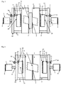
- FIG. 3 shows a first embodiment in which the second actuator 11 is formed by an abutment surface 18 and a screw 19, one of which, the abutment surface 18 as a fixed part 15, is connected to the base frame, and the other, in this case the screw 19, as Losteil 14 slidably mounted relative to the first actuator 7 is, for example, as shown by means of threaded engagement in the sliding element 10 is guided.
- the sliding element 10 connects the loose end 6 of the first actuator 7 with the first carrier 1.
- FIG. 4 shows and makes it clear that according to the invention first and second actuator 7, 11 allow precise positioning of the first carrier 1 against the second carrier 2, so that on the carriers 1, 2 fixed material ends 3, 4 abut each other with their cut end faces.
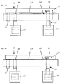
- FIG. 5 shows a rail on which with the connecting element 9 and the sliding element 10 rigidly fixed first carrier 1 is guided, as an example of a guide device 21.
- the device comprises two parallel beams 1, 2, which are each guided in a guide device 21 .
- the first actuator 7 has a slidable cylinder having the loose end 6 of the first actuator 7, the cylinder may form the connecting element 9 and the guide means 21 may be formed by the bore in which the connecting element 9 in the first Actuator 7 is guided.
- FIGS. 5 and 6 are the fixing means 20 and stops 17, is arranged against the material with a side edge, not shown.
- the guide means 21 contributes to bring the carrier 1, 2 precisely in a predetermined position to each other, in which the cutting element 5 intersects the ends to end faces whose orientation is determined by the cutting element.
- the guidance of the first carrier 1 against the second carrier 2, for example along the guide means 21, allows the positionally accurate arrangement of the end faces of Material ends 3, 4 against each other.
- the arrangement of these end faces with a predetermined position against each other is generated by the movement of the first carrier 1 against the second carrier 2 by the actuation of the first actuator 7 and the second actuator 11.
- the preferred procedure is in FIGS. 7 to 14 shown step by step.
- the first embodiment of the device shown here has sliding wedges as a second actuator, of which the wedge connected to the loose end is movable perpendicular to the direction of movement of the first actuator.
- a position sensor is mounted, the signal indicating the position of the displaceable part of this actuator and is preferably used to control an actuator for this displaceable part.
- the carriers 1, 2 are arranged in the cutting position, in which a cutting device, which is designed as a cutting element 5 with two spaced parallel counter knives 22, between the carriers 1, 2 is positioned.
- the edges of the materials are against stops 18, which protrude beyond the carrier 1, 2.
- the fixing devices 20 are not yet arranged against the carrier 1, 2.
- the cutting edges of the counter blades 22 lie in the plane of the beams 1, 2, so that the counter blades 22 abut against the materials which protrude above the beams 1, 2.
- FIG. 8 shows that the fixing means 20, in the present case designed as a clamping bar, fix the materials by parallel method against the carrier 1, 2.
- FIG. 9 shows the optional step to bring the carrier 1, 2 by moving against each other in the cutting position.
- FIG. 10 shows the cutting of the material ends 3, 4 in parallel end faces by moving the cutting element 5 between the counter blade 22. In this position, the end faces of the material ends 3, 4 contact the cutting element. 5
- FIG. 11 shows, it is preferred to avoid mechanical loading of the material ends 3, 4 by the cutting element 5, the carrier 1, 2 away from each other to move until they are moved to a greater distance than they occupy in the cutting position.
- the counter-blade 22 is fixed on its side, which is opposite to the cutting element 5, on a knife carrier 24 whose sides in his Positioning in the cutting position between the carriers 1, 2 stops for the carrier 1, 2 form.
- the knife carrier 24 is frictionally arranged in the cutting position between the carriers 1, 2, so that the carriers 1, 2 are movable to a greater distance, and with the cutting element 5, the knife carrier 24 with the counter knives 22 from the area between the carriers 1, 2 are movable.
- FIG. 12 shows the preferred lowering of the cutting element 5 in a position below the plane of the carrier 1.2.
- the cutting element 5 has a sealing strip 23 on its surface opposite the cutting edge.
- FIG. 13 shows the movement of the carrier 1, 2 against each other to the welding position in which the material ends 3, 4 are positioned at a predetermined distance from each other.
- FIG. 14 shows that a sealing bar 23 against the support 1, 2 projecting material ends 3, 4 can be arranged, in this case by moving the cutting element 5 to the bearing surfaces of the sealing bar 23 are arranged approximately in the plane of the carrier 1, 2, so that they are parallel lie to the material ends 3,4 and arranged between the bearing surfaces groove of the welding bar is parallel to the end faces of the material ends 3, 4.
- the fixing device 20 is a terminal strip, which is guided at the first end 25 of the terminal block on the carrier 1, 2, for example on a column 26, wherein preferably the column 26 is arranged perpendicular to the carrier 1, 2.
- a first clamping drive 27 is arranged, which is connected to a first clamping bar 28 with the terminal block and through which the terminal block against the carrier 1, 2 can be loaded.
- the clamping strip can be connected to the second clamping drive 30 by means of a latching device 31, in which a second clamping rod 32 releasably engages.
- the locking of the second clamping bar 32 with the terminal block in the latching device can, as in FIG. 16 shown, by arranging the second clamping bar 32 in a recess of the terminal block, for example, as in FIG. 17 shown by moving the second clamping bar 32nd
- the first clamping rod 28 and the second clamping rod 32 are arranged in perpendicular to the carrier 1, 2 arranged bores and / or in the hydraulic or pneumatic cylinder.
- FIG. 18 shows that preferably the first and the second clamping drive 27, 30 by means of parallel clamping bar 28, 32 load the terminal strip against the carrier 1, 2, to load the terminal block in parallel alignment against the carrier 1, 2. It has been shown that in this way a material end 3, 4 substantially without deformation on the support, with sufficient clamping force over the entire width of the material, can be fixed. By lowering the second clamping bar 28, the material can be removed after welding to the right.
Landscapes
- Engineering & Computer Science (AREA)
- Mechanical Engineering (AREA)
- Physics & Mathematics (AREA)
- Optics & Photonics (AREA)
- Plasma & Fusion (AREA)
- Lining Or Joining Of Plastics Or The Like (AREA)
- Shearing Machines (AREA)
Claims (13)
- Ensemble pour maintenir et relier deux extrémités (3, 4) d'un matériau, l'ensemble présentant un bâti de base ainsi qu'un premier support (1) et qu'un deuxième support (2) qui présentent tous deux une butée qui déborde d'un support (1, 2) respectif et un dispositif (20) de fixation d'une extrémité (3, 4) du matériau, un dispositif de coupe qui coupe les extrémités (3, 4) du matériau dans leur surface frontale et un dispositif de soudage conçu pour souder l'une à l'autre les deux extrémités (3, 4) du matériau entre le premier support (1) et le deuxième support (2),
caractérisé en ce
que au moins le premier support (1) est guidé à coulissement par rapport au deuxième support (2),
que pour son positionnement, le premier support (1) est relié à un premier organe de réglage (7) et à une deuxième organe de réglage (11) relié au premier,
que le premier organe de réglage (7) est fixé sur le bâti de base par son extrémité fixe (8) et est relié par son extrémité libre (6) à un élément coulissant (10) qui est relié au premier support (1) et
que le deuxième organe de réglage (11) est relié par son extrémité libre (12) à l'élément coulissant (10) et l'extrémité fixe (13) du deuxième organe de réglage (11) est reliée au bâti de base. - Ensemble selon la revendication 1, caractérisé en ce que le deuxième support (2) est guidé à coulissement par rapport au premier support (1) en ce que pour son positionnement, il est relié à un premier organe de réglage (7) et à un deuxième organe de réglage (11) relié au premier.
- Ensemble selon l'une des revendications précédentes, caractérisé en ce que le deuxième organe de réglage (11) est disposé entre l'extrémité libre (6) du premier organe de réglage (7) et le premier support (1).
- Ensemble selon l'une des revendications précédentes, caractérisé en ce que le deuxième organe de réglage (11) présente à son extrémité fixe un biseau fixe (15) et à son extrémité libre un biseau libre (14), au l'un de ces biseaux pouvant coulisser par rapport à l'autre.
- Ensemble selon l'une des revendications 1 à 3, caractérisé en ce que le deuxième organe de réglage présente une surface de butée (18) et une vis de réglage (19) guidée en direction de la de butée (18).
- Ensemble selon l'une des revendications précédentes, caractérisé par un capteur conçu pour déterminer le positionnement mutuel des parties du deuxième organe de réglage ou pour mesurer la distance entre le premier support (1) et le deuxième support (2), et un dispositif de commande conçu pour commander le deuxième organe de réglage (11) en fonction du signal du capteur.
- Ensemble selon l'une des revendications précédentes, caractérisé par un capteur de force conçu pour mesurer la force qui agit entre le premier support (1) et le deuxième support (2), et un dispositif de commande conçu pour commander le deuxième organe de réglage (11) en fonction du signal du capteur de force.
- Ensemble selon l'une des revendications précédentes, caractérisé en ce qu'au moins le premier support (1) est fixé sur un élément de liaison (9) et en ce que le premier support (1) est guidé à déplacement linéaire sur le bâti de base par un dispositif de guidage (21).
- Ensemble selon l'une des revendications précédentes, caractérisé en ce que le dispositif de fixation (20) est une barre de serrage dont au moins certaines parties présentent une surface de serrage parallèle au plan des supports (1, 2), qui est guidée par sa première extrémité sur un support (1, 2) et qui peut être sollicitée en direction du support (1, 2) au moyen d'un premier entraînement de serrage (27), tandis qu'à sa deuxième extrémité (29) séparée de la première extrémité (25) par la surface de serrage, la barre de serrage peut être engagée et sollicitée en direction du support (1, 2) par un deuxième entraînement de serrage (30).
- Ensemble selon l'une des revendications précédentes, caractérisé en ce que les supports (1, 2) peuvent être positionnés de manière contrôlée dans une position de coupe, en ce qu'un élément de coupe (5) du dispositif de coupe peut être déplacé entre les supports (1, 2) pour être amené en position de coupe, en ce que les supports (1, 2) peuvent être écartées d'une distance plus grande que celle qu'ils prennent en position de coupe et en ce que l'élément de coupe (5) peut être sorti de la zone située entre les supports (1, 2).
- Ensemble selon l'une des revendications précédentes, caractérisé en ce que l'élément de coupe (5) présente une latte de coupe qui présente deux surfaces de pose séparées par une rainure, orientées parallèlement au plan des supports et aptes à être placées en position adjacente au plan dans lequel les supports (1, 2) s'étendent.
- Procédé de préparation d'extrémités (3, 4) de matériau soudées par leurs surfaces frontales placées bout-à-bout, le procédé présentant les étapes qui consistent à :fixer une première extrémité (3) du matériau sur un premier support (1) et fixer une deuxième extrémité (4) du matériau sur un deuxième support (2),découper les extrémités (3, 4) du matériau sur des surfaces frontales mutuellement parallèles et situées l'une en face de l'autre,déplacer le premier support (1) fixé sur un élément de liaison (9), en direction du deuxième support (2) et le long d'un dispositif de guidage (21) jusqu'à ce que les surfaces frontales des extrémités (3, 4) du matériau reposent l'une contre l'autre dans une position prédéfinie, par actionnement d'un premier organe de réglage (7), et souder des surfaces frontales des extrémités (3, 4) du matériau disposées l'une contre l'autre,
caractérisé en ceque en ce que le premier organe de réglage (7) est fixé sur le bâti de base par son extrémité fixe (8) et est relié par son extrémité libre (6) à un élément coulissant (10) qui est relié au premier support (1) eten ce que le deuxième organe de réglage (11) est relié par son extrémité libre (12) à l'élément coulissant (10) et l'extrémité fixe (13) du deuxième organe de réglage (11) est reliée au bâti de base. - Procédé selon la revendication 14, caractérisé en ce qu'avant la découpe, le premier support (1) et le deuxième support (2) sont déplacés dans une position de coupe, en ce que les extrémités (3, 4) du matériau sont découpées au moyen d'un élément de coupe (5) déplacé entre les supports (1, 2), en ce qu'après la découpe, les supports (1, 2) sont écartés l'un de l'autre et l'élément de coupe est subséquemment déplacé hors de la chambre entre les supports (1, 2) et les supports (1, 2) sont déplacés dans la position de soudage dans laquelle les extrémités (3, 4) du matériau sont positionnées à une distance mutuelle prédéterminée, une latte de soudage étant disposée en position adjacente aux extrémités (3, 4) du matériau pendant le soudage.
Priority Applications (2)
| Application Number | Priority Date | Filing Date | Title |
|---|---|---|---|
| EP11306506.4A EP2594355B1 (fr) | 2011-11-17 | 2011-11-17 | Machine et méthode de coupage et de soudage avec un dispositif de positionnement de deux extrémités de matériaux l'une contre l'autre |
| US13/678,643 US8800845B2 (en) | 2011-11-17 | 2012-11-16 | Device for transverse seam welding |
Applications Claiming Priority (1)
| Application Number | Priority Date | Filing Date | Title |
|---|---|---|---|
| EP11306506.4A EP2594355B1 (fr) | 2011-11-17 | 2011-11-17 | Machine et méthode de coupage et de soudage avec un dispositif de positionnement de deux extrémités de matériaux l'une contre l'autre |
Publications (2)
| Publication Number | Publication Date |
|---|---|
| EP2594355A1 EP2594355A1 (fr) | 2013-05-22 |
| EP2594355B1 true EP2594355B1 (fr) | 2016-06-08 |
Family
ID=45217451
Family Applications (1)
| Application Number | Title | Priority Date | Filing Date |
|---|---|---|---|
| EP11306506.4A Active EP2594355B1 (fr) | 2011-11-17 | 2011-11-17 | Machine et méthode de coupage et de soudage avec un dispositif de positionnement de deux extrémités de matériaux l'une contre l'autre |
Country Status (2)
| Country | Link |
|---|---|
| US (1) | US8800845B2 (fr) |
| EP (1) | EP2594355B1 (fr) |
Families Citing this family (9)
| Publication number | Priority date | Publication date | Assignee | Title |
|---|---|---|---|---|
| US10821548B2 (en) * | 2015-03-20 | 2020-11-03 | Honda Motor Co., Ltd. | Plate-material abutting device |
| KR20180122744A (ko) * | 2016-04-04 | 2018-11-13 | 쉴로 인더스트리즈 인코포레이티드 | 진공 기반의 용접 장치 및 이를 사용하는 방법 |
| CN105729027B (zh) * | 2016-05-09 | 2017-11-21 | 杭州焊林科技有限公司 | 焊接工件固定设备 |
| CN106736118A (zh) * | 2016-12-30 | 2017-05-31 | 安徽泰富重工制造有限公司 | 一种多功能焊机装置 |
| CN109967935A (zh) * | 2017-12-28 | 2019-07-05 | 刘海平 | 一种汽车配件的焊接定位装置 |
| CN111250915A (zh) * | 2020-03-23 | 2020-06-09 | 中国五冶集团有限公司 | 一种钢板对缝装置 |
| US11607754B2 (en) * | 2020-07-20 | 2023-03-21 | Crown Equipment Corporation | Alignment spacer assemblies for welding and methods for using same |
| CN117342233B (zh) * | 2023-11-20 | 2024-05-28 | 中国机械总院集团哈尔滨焊接研究所有限公司 | 一种铲板槽帮的定位摆正装置及其定位摆正方法 |
| CN117662965B (zh) * | 2023-12-13 | 2026-03-31 | 湖南响箭氢能新能源有限公司 | 一种多层包扎式储氢罐钢板端部对齐设备 |
Family Cites Families (32)
| Publication number | Priority date | Publication date | Assignee | Title |
|---|---|---|---|---|
| US2120316A (en) * | 1937-04-03 | 1938-06-14 | United Eng Foundry Co | Apparatus for welding and flash trimmings |
| US2143969A (en) * | 1937-06-29 | 1939-01-17 | United Eng Foundry Co | Method and apparatus for welding strip end to end |
| US2649528A (en) | 1950-09-27 | 1953-08-18 | New Haven Copper Company | Welding ends of copper coils |
| US2911515A (en) * | 1956-10-16 | 1959-11-03 | Taylor Winfield Corp | Narrow lap seam welder |
| US3403833A (en) * | 1966-04-08 | 1968-10-01 | Guild Metal Joining Equipment | Strip clamp assembly |
| US3386640A (en) * | 1966-08-25 | 1968-06-04 | Voss Engineering Company | Shearing and welding apparatus |
| US3458103A (en) * | 1966-09-26 | 1969-07-29 | First Western Bank & Trust Co | Strip joining apparatus and method |
| DE2341255C2 (de) * | 1973-08-16 | 1982-08-26 | Hugo Miebach Gmbh, 4600 Dortmund | Abbrennstumpfschweißmaschine zum Verbinden von Bändern |
| JPS51137637A (en) * | 1975-05-23 | 1976-11-27 | Ishikawajima Harima Heavy Ind | Method and device for butt welding |
| JPS5261143A (en) * | 1975-11-14 | 1977-05-20 | Ishikawajima Harima Heavy Ind | Butt welding process and device |
| JPS5418442A (en) * | 1977-07-12 | 1979-02-10 | Nippon Steel Corp | Flash welding equipment |
| US4286744A (en) * | 1979-11-21 | 1981-09-01 | Olin Corporation | Process for joining narrow width thin gage metal or alloy strip |
| DE151848T1 (de) * | 1984-02-27 | 1985-12-05 | Kawasaki Steel Corp., Kobe, Hyogo | Vorrichtung zum stumpfschweissen von stahlbaendern mit einem laserstrahl in einer stahlbandverarbeitungsstrasse. |
| US4721241A (en) * | 1986-11-21 | 1988-01-26 | Kawasaki Steel Corporation | Welding apparatus assembled together with grinding device |
| DE3809713C1 (en) * | 1988-03-23 | 1989-04-20 | Oxytechnik Gesellschaft Fuer Systemtechnik Mbh, 6236 Eschborn, De | Strip-welding unit and method of setting the welding gap of strip ends |
| EP0492368B1 (fr) * | 1990-12-20 | 1996-05-08 | Mitsubishi Jukogyo Kabushiki Kaisha | Dispositif pour souder bout à bout des tÔles d'acier courantes |
| DE4100302C1 (fr) * | 1991-01-08 | 1992-02-06 | Bwg Bergwerk- Und Walzwerk-Maschinenbau Gmbh, 4100 Duisburg, De | |
| JP2932779B2 (ja) * | 1991-09-04 | 1999-08-09 | 株式会社明電舎 | 突合わせ溶接機の後加熱装置 |
| SE501343C2 (sv) * | 1993-06-11 | 1995-01-23 | Volvo Ab | Anordning för lägesfixering av plåtar vid svetsning |
| US5456405A (en) | 1993-12-03 | 1995-10-10 | Quality Tubing Inc. | Dual bias weld for continuous coiled tubing |
| US5674412A (en) * | 1995-03-28 | 1997-10-07 | Ege; Sigmund | Butt splicer for copper based tapes |
| US6213381B1 (en) * | 1996-10-25 | 2001-04-10 | Hitachi, Ltd. | Method of bonding metal plates, apparatus therefor and hot strip mill |
| FR2756504B1 (fr) * | 1996-11-29 | 1999-05-07 | Kvaerner Clecim | Machine automatique de raccordement transversal de bandes metalliques |
| US5992726A (en) * | 1998-01-08 | 1999-11-30 | Iron Bay | Apparatus and method for setting welding run-off tabs in a coil end joiner |
| US6244494B1 (en) * | 1999-06-11 | 2001-06-12 | Iron Bay, Inc. | Apparatus and method for leveling the clamping surface to provide proper heat sink for narrow strips in coil end joiner |
| JP4445633B2 (ja) * | 2000-02-28 | 2010-04-07 | 菊池プレス工業株式会社 | シーム溶接方法及びその装置 |
| JP2002035944A (ja) * | 2000-07-28 | 2002-02-05 | Mitsubishi Electric Corp | シーム溶接装置とシーム溶接方法 |
| JP4636261B2 (ja) * | 2005-10-14 | 2011-02-23 | トヨタ自動車株式会社 | 鋼板の突合せ溶接システム及び鋼板の突合せ溶接方法 |
| EP1960132B1 (fr) * | 2006-04-27 | 2009-07-15 | SMS Siemag AG | Système et methode d'assemblage de bandes |
| UA96227C2 (ru) * | 2007-12-05 | 2011-10-10 | Смс Зимаг Аг | Устройство и способ для соединения полос |
| IT1391660B1 (it) * | 2008-11-10 | 2012-01-17 | Danieli Off Mecc | Sistema di saldatura di nastri metallici |
| JP5057477B2 (ja) | 2009-01-15 | 2012-10-24 | 日本オクラロ株式会社 | 半導体レーザ素子 |
-
2011
- 2011-11-17 EP EP11306506.4A patent/EP2594355B1/fr active Active
-
2012
- 2012-11-16 US US13/678,643 patent/US8800845B2/en active Active
Also Published As
| Publication number | Publication date |
|---|---|
| US8800845B2 (en) | 2014-08-12 |
| EP2594355A1 (fr) | 2013-05-22 |
| US20130313308A1 (en) | 2013-11-28 |
Similar Documents
| Publication | Publication Date | Title |
|---|---|---|
| EP2594355A1 (fr) | Machine de coupage et de soudage avec un dispositif de positionnement de deux extrémités de matériaux l'une contre l'autre | |
| DE69707813T2 (de) | Automatische Maschine zum transversal Verbinden von Metallbändern | |
| DE102007013455B4 (de) | Vorrichtung zum Schneiden von Bändern, Blechen oder dergleichen und Verfahren zur Bestimmung und/oder Kalibrierung des Schneidspaltes bei einer solchen Vorrichtung | |
| DE69403932T2 (de) | Bearbeitungsstation mit Stümpfpositionierung und Laserstrahlschweissen von zwei Blechkanten | |
| DE69717132T2 (de) | Vorrichtung zum oszillierenden reibschweissen | |
| DE3905788C2 (de) | Schneidwerkzeug zum Einschneiden von Rohren, um deren Biegung zu erleichtern | |
| DE102018130769B3 (de) | Vorrichtung und Verfahren zum Stumpfschweißen von Werkstücken | |
| EP2340147B1 (fr) | Machine d'usinage pour usinage de six faces | |
| EP1287918B1 (fr) | Procédé et dispositif pour la formation d'un coin limité sur trois côtés à partir d'un matériau en feuille plane | |
| EP2070686B1 (fr) | Dispositif et procédé destinés au soudage de pièces de profilés en matière plastique | |
| DE19750480A1 (de) | Fliesenschneidgerät | |
| DE69909977T2 (de) | Vorrichtung zum Stumpf-Laserschweissen von Blechen (vorbestimmten Zuschnitten), die magnetische Rollen hat um die Bleche nach der Schweissposition zu bewegen und die aktive Klemmen hat, um die Bleche zu klemmen | |
| DE2128717C3 (de) | Verfahren zum Aufbringen eines metallischen Abstandhalters auf die Scheibenränder einer der rechteckigen Glasplatten einer Isolierverglasung und Vorrichtung zur Durchführung des Verfahrens | |
| EP3238848B1 (fr) | Procédé de compensation du décalage due à la fabrication dans un coulisseau porte-outil | |
| EP1810769A1 (fr) | Machine à usiner des panneaux avec unité de sciage | |
| EP3113941B1 (fr) | Coulisseau porte-outil | |
| DE3920825C2 (de) | Vorrichtung zum Beschneiden und Stumpfschweißen von Band- oder Blechrändern mit einer Lasereinrichtung | |
| EP3969217B1 (fr) | Table transversale pour une machine d'usinage du bois, et machine d'usinage du bois comprenant une table transversale de ce type, et procédé de commande d'une machine d'usinage du bois | |
| EP1543906A1 (fr) | Unité d'usinage pour le traitement des joints d'angle de cadres en profilés soudés | |
| EP4526073A1 (fr) | Machine de soudage en bout par étincelage de bande et groupe d'accessoires pour une machine de soudage en bout par étincelage de bande | |
| AT409606B (de) | Plattenaufteilsäge | |
| DE102014116972B4 (de) | Verfahren und Vorrichtung zum Einstellen eines Messerpakets eines Messerrings auf einen vorbestimmten Messervorstand | |
| DE102014210867B4 (de) | Platinenschneidwerkzeug mit mehreren Schneidstationen | |
| AT501316B1 (de) | Plattenaufteilsäge mit niederhaltevorrichtung | |
| DE2427434A1 (de) | Vorrichtung zur herstellung von nuten in folien, insbesondere aus polypropylen |
Legal Events
| Date | Code | Title | Description |
|---|---|---|---|
| PUAI | Public reference made under article 153(3) epc to a published international application that has entered the european phase |
Free format text: ORIGINAL CODE: 0009012 |
|
| 17P | Request for examination filed |
Effective date: 20120717 |
|
| AK | Designated contracting states |
Kind code of ref document: A1 Designated state(s): AL AT BE BG CH CY CZ DE DK EE ES FI FR GB GR HR HU IE IS IT LI LT LU LV MC MK MT NL NO PL PT RO RS SE SI SK SM TR |
|
| AX | Request for extension of the european patent |
Extension state: BA ME |
|
| RIC1 | Information provided on ipc code assigned before grant |
Ipc: B23K 37/04 20060101ALI20140918BHEP Ipc: B21C 37/26 20060101ALI20140918BHEP Ipc: B23K 37/047 20060101ALI20140918BHEP Ipc: B23K 9/025 20060101AFI20140918BHEP Ipc: B21D 39/03 20060101ALI20140918BHEP Ipc: B23K 26/26 20140101ALI20140918BHEP |
|
| GRAP | Despatch of communication of intention to grant a patent |
Free format text: ORIGINAL CODE: EPIDOSNIGR1 |
|
| INTG | Intention to grant announced |
Effective date: 20141031 |
|
| 17Q | First examination report despatched |
Effective date: 20141212 |
|
| INTG | Intention to grant announced |
Effective date: 20160108 |
|
| GRAS | Grant fee paid |
Free format text: ORIGINAL CODE: EPIDOSNIGR3 |
|
| GRAA | (expected) grant |
Free format text: ORIGINAL CODE: 0009210 |
|
| AK | Designated contracting states |
Kind code of ref document: B1 Designated state(s): AL AT BE BG CH CY CZ DE DK EE ES FI FR GB GR HR HU IE IS IT LI LT LU LV MC MK MT NL NO PL PT RO RS SE SI SK SM TR |
|
| REG | Reference to a national code |
Ref country code: GB Ref legal event code: FG4D Free format text: NOT ENGLISH |
|
| REG | Reference to a national code |
Ref country code: CH Ref legal event code: EP |
|
| REG | Reference to a national code |
Ref country code: IE Ref legal event code: FG4D Free format text: LANGUAGE OF EP DOCUMENT: GERMAN |
|
| REG | Reference to a national code |
Ref country code: AT Ref legal event code: REF Ref document number: 804848 Country of ref document: AT Kind code of ref document: T Effective date: 20160715 |
|
| REG | Reference to a national code |
Ref country code: DE Ref legal event code: R096 Ref document number: 502011009909 Country of ref document: DE |
|
| REG | Reference to a national code |
Ref country code: NL Ref legal event code: MP Effective date: 20160608 |
|
| REG | Reference to a national code |
Ref country code: LT Ref legal event code: MG4D |
|
| PG25 | Lapsed in a contracting state [announced via postgrant information from national office to epo] |
Ref country code: LT Free format text: LAPSE BECAUSE OF FAILURE TO SUBMIT A TRANSLATION OF THE DESCRIPTION OR TO PAY THE FEE WITHIN THE PRESCRIBED TIME-LIMIT Effective date: 20160608 Ref country code: FI Free format text: LAPSE BECAUSE OF FAILURE TO SUBMIT A TRANSLATION OF THE DESCRIPTION OR TO PAY THE FEE WITHIN THE PRESCRIBED TIME-LIMIT Effective date: 20160608 Ref country code: NO Free format text: LAPSE BECAUSE OF FAILURE TO SUBMIT A TRANSLATION OF THE DESCRIPTION OR TO PAY THE FEE WITHIN THE PRESCRIBED TIME-LIMIT Effective date: 20160908 Ref country code: NL Free format text: LAPSE BECAUSE OF FAILURE TO SUBMIT A TRANSLATION OF THE DESCRIPTION OR TO PAY THE FEE WITHIN THE PRESCRIBED TIME-LIMIT Effective date: 20160608 |
|
| PG25 | Lapsed in a contracting state [announced via postgrant information from national office to epo] |
Ref country code: RS Free format text: LAPSE BECAUSE OF FAILURE TO SUBMIT A TRANSLATION OF THE DESCRIPTION OR TO PAY THE FEE WITHIN THE PRESCRIBED TIME-LIMIT Effective date: 20160608 Ref country code: LV Free format text: LAPSE BECAUSE OF FAILURE TO SUBMIT A TRANSLATION OF THE DESCRIPTION OR TO PAY THE FEE WITHIN THE PRESCRIBED TIME-LIMIT Effective date: 20160608 Ref country code: ES Free format text: LAPSE BECAUSE OF FAILURE TO SUBMIT A TRANSLATION OF THE DESCRIPTION OR TO PAY THE FEE WITHIN THE PRESCRIBED TIME-LIMIT Effective date: 20160608 Ref country code: GR Free format text: LAPSE BECAUSE OF FAILURE TO SUBMIT A TRANSLATION OF THE DESCRIPTION OR TO PAY THE FEE WITHIN THE PRESCRIBED TIME-LIMIT Effective date: 20160909 Ref country code: HR Free format text: LAPSE BECAUSE OF FAILURE TO SUBMIT A TRANSLATION OF THE DESCRIPTION OR TO PAY THE FEE WITHIN THE PRESCRIBED TIME-LIMIT Effective date: 20160608 Ref country code: SE Free format text: LAPSE BECAUSE OF FAILURE TO SUBMIT A TRANSLATION OF THE DESCRIPTION OR TO PAY THE FEE WITHIN THE PRESCRIBED TIME-LIMIT Effective date: 20160608 |
|
| PG25 | Lapsed in a contracting state [announced via postgrant information from national office to epo] |
Ref country code: SK Free format text: LAPSE BECAUSE OF FAILURE TO SUBMIT A TRANSLATION OF THE DESCRIPTION OR TO PAY THE FEE WITHIN THE PRESCRIBED TIME-LIMIT Effective date: 20160608 Ref country code: EE Free format text: LAPSE BECAUSE OF FAILURE TO SUBMIT A TRANSLATION OF THE DESCRIPTION OR TO PAY THE FEE WITHIN THE PRESCRIBED TIME-LIMIT Effective date: 20160608 Ref country code: RO Free format text: LAPSE BECAUSE OF FAILURE TO SUBMIT A TRANSLATION OF THE DESCRIPTION OR TO PAY THE FEE WITHIN THE PRESCRIBED TIME-LIMIT Effective date: 20160608 Ref country code: IS Free format text: LAPSE BECAUSE OF FAILURE TO SUBMIT A TRANSLATION OF THE DESCRIPTION OR TO PAY THE FEE WITHIN THE PRESCRIBED TIME-LIMIT Effective date: 20161008 Ref country code: CZ Free format text: LAPSE BECAUSE OF FAILURE TO SUBMIT A TRANSLATION OF THE DESCRIPTION OR TO PAY THE FEE WITHIN THE PRESCRIBED TIME-LIMIT Effective date: 20160608 |
|
| PG25 | Lapsed in a contracting state [announced via postgrant information from national office to epo] |
Ref country code: SM Free format text: LAPSE BECAUSE OF FAILURE TO SUBMIT A TRANSLATION OF THE DESCRIPTION OR TO PAY THE FEE WITHIN THE PRESCRIBED TIME-LIMIT Effective date: 20160608 Ref country code: BE Free format text: LAPSE BECAUSE OF NON-PAYMENT OF DUE FEES Effective date: 20161130 Ref country code: PL Free format text: LAPSE BECAUSE OF FAILURE TO SUBMIT A TRANSLATION OF THE DESCRIPTION OR TO PAY THE FEE WITHIN THE PRESCRIBED TIME-LIMIT Effective date: 20160608 Ref country code: PT Free format text: LAPSE BECAUSE OF FAILURE TO SUBMIT A TRANSLATION OF THE DESCRIPTION OR TO PAY THE FEE WITHIN THE PRESCRIBED TIME-LIMIT Effective date: 20161010 |
|
| REG | Reference to a national code |
Ref country code: DE Ref legal event code: R097 Ref document number: 502011009909 Country of ref document: DE |
|
| PLBE | No opposition filed within time limit |
Free format text: ORIGINAL CODE: 0009261 |
|
| STAA | Information on the status of an ep patent application or granted ep patent |
Free format text: STATUS: NO OPPOSITION FILED WITHIN TIME LIMIT |
|
| 26N | No opposition filed |
Effective date: 20170309 |
|
| PG25 | Lapsed in a contracting state [announced via postgrant information from national office to epo] |
Ref country code: SI Free format text: LAPSE BECAUSE OF FAILURE TO SUBMIT A TRANSLATION OF THE DESCRIPTION OR TO PAY THE FEE WITHIN THE PRESCRIBED TIME-LIMIT Effective date: 20160608 Ref country code: DK Free format text: LAPSE BECAUSE OF FAILURE TO SUBMIT A TRANSLATION OF THE DESCRIPTION OR TO PAY THE FEE WITHIN THE PRESCRIBED TIME-LIMIT Effective date: 20160608 |
|
| GBPC | Gb: european patent ceased through non-payment of renewal fee |
Effective date: 20161117 |
|
| REG | Reference to a national code |
Ref country code: IE Ref legal event code: MM4A |
|
| REG | Reference to a national code |
Ref country code: FR Ref legal event code: ST Effective date: 20170731 |
|
| PG25 | Lapsed in a contracting state [announced via postgrant information from national office to epo] |
Ref country code: LU Free format text: LAPSE BECAUSE OF NON-PAYMENT OF DUE FEES Effective date: 20161130 |
|
| PG25 | Lapsed in a contracting state [announced via postgrant information from national office to epo] |
Ref country code: FR Free format text: LAPSE BECAUSE OF NON-PAYMENT OF DUE FEES Effective date: 20161130 |
|
| PG25 | Lapsed in a contracting state [announced via postgrant information from national office to epo] |
Ref country code: GB Free format text: LAPSE BECAUSE OF NON-PAYMENT OF DUE FEES Effective date: 20161117 Ref country code: IE Free format text: LAPSE BECAUSE OF NON-PAYMENT OF DUE FEES Effective date: 20161117 |
|
| REG | Reference to a national code |
Ref country code: BE Ref legal event code: MM Effective date: 20161130 |
|
| PG25 | Lapsed in a contracting state [announced via postgrant information from national office to epo] |
Ref country code: CY Free format text: LAPSE BECAUSE OF FAILURE TO SUBMIT A TRANSLATION OF THE DESCRIPTION OR TO PAY THE FEE WITHIN THE PRESCRIBED TIME-LIMIT Effective date: 20160608 Ref country code: HU Free format text: LAPSE BECAUSE OF FAILURE TO SUBMIT A TRANSLATION OF THE DESCRIPTION OR TO PAY THE FEE WITHIN THE PRESCRIBED TIME-LIMIT; INVALID AB INITIO Effective date: 20111117 |
|
| PG25 | Lapsed in a contracting state [announced via postgrant information from national office to epo] |
Ref country code: MK Free format text: LAPSE BECAUSE OF FAILURE TO SUBMIT A TRANSLATION OF THE DESCRIPTION OR TO PAY THE FEE WITHIN THE PRESCRIBED TIME-LIMIT Effective date: 20160608 Ref country code: MC Free format text: LAPSE BECAUSE OF FAILURE TO SUBMIT A TRANSLATION OF THE DESCRIPTION OR TO PAY THE FEE WITHIN THE PRESCRIBED TIME-LIMIT Effective date: 20160608 Ref country code: TR Free format text: LAPSE BECAUSE OF FAILURE TO SUBMIT A TRANSLATION OF THE DESCRIPTION OR TO PAY THE FEE WITHIN THE PRESCRIBED TIME-LIMIT Effective date: 20160608 |
|
| PG25 | Lapsed in a contracting state [announced via postgrant information from national office to epo] |
Ref country code: BG Free format text: LAPSE BECAUSE OF FAILURE TO SUBMIT A TRANSLATION OF THE DESCRIPTION OR TO PAY THE FEE WITHIN THE PRESCRIBED TIME-LIMIT Effective date: 20160608 |
|
| PG25 | Lapsed in a contracting state [announced via postgrant information from national office to epo] |
Ref country code: MT Free format text: LAPSE BECAUSE OF FAILURE TO SUBMIT A TRANSLATION OF THE DESCRIPTION OR TO PAY THE FEE WITHIN THE PRESCRIBED TIME-LIMIT Effective date: 20160608 |
|
| PG25 | Lapsed in a contracting state [announced via postgrant information from national office to epo] |
Ref country code: AL Free format text: LAPSE BECAUSE OF FAILURE TO SUBMIT A TRANSLATION OF THE DESCRIPTION OR TO PAY THE FEE WITHIN THE PRESCRIBED TIME-LIMIT Effective date: 20160608 |
|
| REG | Reference to a national code |
Ref country code: CH Ref legal event code: U11 Free format text: ST27 STATUS EVENT CODE: U-0-0-U10-U11 (AS PROVIDED BY THE NATIONAL OFFICE) Effective date: 20251201 |
|
| PGFP | Annual fee paid to national office [announced via postgrant information from national office to epo] |
Ref country code: DE Payment date: 20251119 Year of fee payment: 15 |
|
| PGFP | Annual fee paid to national office [announced via postgrant information from national office to epo] |
Ref country code: AT Payment date: 20251120 Year of fee payment: 15 |
|
| PGFP | Annual fee paid to national office [announced via postgrant information from national office to epo] |
Ref country code: IT Payment date: 20251125 Year of fee payment: 15 |
|
| PGFP | Annual fee paid to national office [announced via postgrant information from national office to epo] |
Ref country code: CH Payment date: 20251201 Year of fee payment: 15 |