EP2594453A2 - Transportwagen, insbesondere für Sterilgut - Google Patents
Transportwagen, insbesondere für Sterilgut Download PDFInfo
- Publication number
- EP2594453A2 EP2594453A2 EP12192290.0A EP12192290A EP2594453A2 EP 2594453 A2 EP2594453 A2 EP 2594453A2 EP 12192290 A EP12192290 A EP 12192290A EP 2594453 A2 EP2594453 A2 EP 2594453A2
- Authority
- EP
- European Patent Office
- Prior art keywords
- slots
- trolley according
- housing
- suspension
- support
- Prior art date
- Legal status (The legal status is an assumption and is not a legal conclusion. Google has not performed a legal analysis and makes no representation as to the accuracy of the status listed.)
- Granted
Links
Images


Classifications
-
- A—HUMAN NECESSITIES
- A61—MEDICAL OR VETERINARY SCIENCE; HYGIENE
- A61G—TRANSPORT, PERSONAL CONVEYANCES, OR ACCOMMODATION SPECIALLY ADAPTED FOR PATIENTS OR DISABLED PERSONS; OPERATING TABLES OR CHAIRS; CHAIRS FOR DENTISTRY; FUNERAL DEVICES
- A61G12/00—Accommodation for nursing, e.g. in hospitals, not covered by groups A61G1/00 - A61G11/00, e.g. trolleys for transport of medicaments or food; Prescription lists
-
- A—HUMAN NECESSITIES
- A61—MEDICAL OR VETERINARY SCIENCE; HYGIENE
- A61B—DIAGNOSIS; SURGERY; IDENTIFICATION
- A61B50/00—Containers, covers, furniture or holders specially adapted for surgical or diagnostic appliances or instruments, e.g. sterile covers
- A61B50/10—Furniture specially adapted for surgical or diagnostic appliances or instruments
- A61B50/13—Trolleys, e.g. carts
-
- A—HUMAN NECESSITIES
- A61—MEDICAL OR VETERINARY SCIENCE; HYGIENE
- A61G—TRANSPORT, PERSONAL CONVEYANCES, OR ACCOMMODATION SPECIALLY ADAPTED FOR PATIENTS OR DISABLED PERSONS; OPERATING TABLES OR CHAIRS; CHAIRS FOR DENTISTRY; FUNERAL DEVICES
- A61G12/00—Accommodation for nursing, e.g. in hospitals, not covered by groups A61G1/00 - A61G11/00, e.g. trolleys for transport of medicaments or food; Prescription lists
- A61G12/001—Trolleys for transport of medicaments, food, linen, nursing supplies
-
- B—PERFORMING OPERATIONS; TRANSPORTING
- B62—LAND VEHICLES FOR TRAVELLING OTHERWISE THAN ON RAILS
- B62B—HAND-PROPELLED VEHICLES, e.g. HAND CARTS OR PERAMBULATORS; SLEDGES
- B62B3/00—Hand carts having more than one axis carrying transport wheels; Steering devices therefor; Equipment therefor
- B62B3/002—Hand carts having more than one axis carrying transport wheels; Steering devices therefor; Equipment therefor characterised by a rectangular shape, involving sidewalls or racks
- B62B3/005—Details of storage means, e.g. drawers, bins or racks
-
- A—HUMAN NECESSITIES
- A61—MEDICAL OR VETERINARY SCIENCE; HYGIENE
- A61B—DIAGNOSIS; SURGERY; IDENTIFICATION
- A61B50/00—Containers, covers, furniture or holders specially adapted for surgical or diagnostic appliances or instruments, e.g. sterile covers
- A61B50/10—Furniture specially adapted for surgical or diagnostic appliances or instruments
- A61B2050/105—Cabinets
-
- B—PERFORMING OPERATIONS; TRANSPORTING
- B62—LAND VEHICLES FOR TRAVELLING OTHERWISE THAN ON RAILS
- B62B—HAND-PROPELLED VEHICLES, e.g. HAND CARTS OR PERAMBULATORS; SLEDGES
- B62B2205/00—Hand-propelled vehicles or sledges being foldable or dismountable when not in use
- B62B2205/30—Detachable, retractable or collapsible load supporting means
- B62B2205/32—Shelves
-
- B—PERFORMING OPERATIONS; TRANSPORTING
- B62—LAND VEHICLES FOR TRAVELLING OTHERWISE THAN ON RAILS
- B62B—HAND-PROPELLED VEHICLES, e.g. HAND CARTS OR PERAMBULATORS; SLEDGES
- B62B2206/00—Adjustable or convertible hand-propelled vehicles or sledges
- B62B2206/06—Adjustable or convertible hand-propelled vehicles or sledges adjustable in height
-
- B—PERFORMING OPERATIONS; TRANSPORTING
- B62—LAND VEHICLES FOR TRAVELLING OTHERWISE THAN ON RAILS
- B62B—HAND-PROPELLED VEHICLES, e.g. HAND CARTS OR PERAMBULATORS; SLEDGES
- B62B3/00—Hand carts having more than one axis carrying transport wheels; Steering devices therefor; Equipment therefor
- B62B3/002—Hand carts having more than one axis carrying transport wheels; Steering devices therefor; Equipment therefor characterised by a rectangular shape, involving sidewalls or racks
- B62B3/003—Non-transparent side walls
Definitions
- the invention relates to a trolley, in particular for sterile goods, with a chassis, arranged on the chassis housing having a rear wall and two side walls and is closed at its front by a single or double-leaf door, and with at least one height-adjustable support.
- the support is supported on connectors which extend parallel to the side walls of the housing and are secured to vertical rails in the interior of the housing.
- the trolley can be used in clean and unclean clinical areas for the safe and hygienic transport of sterile goods.
- the support often consists of a wire grid or a perforated plate. Different designs of the support allow the transport and storage of sterile goods in baskets, sieve trays, containers, sterile foil packaging and disposable packaging.
- the vertical rails consist of bars on which protruding pins are arranged.
- the connectors for supporting a grate or other support have at their ends angled tabs, one tab containing a bore and the other tab contains a C-shaped punched.
- the connectors are attached at one end to a protruding pin of the spars and attached at its other end to a protruding pin.
- the stability of the suspension is still in need of improvement. Furthermore, there is a risk that paper or foil packaging of the items to be sterilized will be damaged on the projecting pins of the spars.
- the DE 101 56 602 C1 discloses a trolley, in particular for sterile goods, with vertical support beams.
- the support beams are provided with preferably equidistantly arranged cutouts in which mounting brackets can be suspended, on which transport containers can be arranged.
- the cutouts are arranged according to the drawings on both the front and the rear vertical support beams front.
- Another trolley especially for sterile goods, is in the DE 101 55 515 A1 described.
- all components of the frame including vertically extending support beams, designed as at least unilaterally open profiles.
- support beams For direct reception of insert elements while recesses are provided in the support beams, which are preferably arranged on the inner legs of the profile.
- the invention has for its object to provide a trolley for sterile goods, whose requirements for the sterile goods without tools in a given grid are height adjustable.
- the position, number and type of circulation should be changeable and replaceable at any time. In this case, both on the vertical rails and on the connectors for supporting the supports projecting parts where foil or paper packaging of the sterile goods can be damaged to avoid.
- the object of the invention and solution of this problem is a trolley according to claim 1.
- the connectors are designed as suspension connectors, which can be hooked at their one end into slots of a vertical rail arranged on the front side of the housing and at their other end in slots of a vertical rail adjacent to the rear wall of the housing.
- the slots of the front-side vertical rail and the slots of the vertical rail adjacent to the rear wall of the housing are arranged in suspension surfaces of the vertical rails, which are oriented orthogonally to each other.
- the suspension surface of a vertical rail thus extends parallel to the rear wall, while the suspension surface of the other vertical rail is aligned parallel to the side wall of the housing.
- the slots of the vertical rails extend in particular vertically and are preferably arranged in the vertical rails with a uniform grid dimension selected between 50 mm and 70 mm. Particularly preferred is a grid of about 60 mm.
- the mounting surface of the front vertical rail extends parallel to the side wall of the housing.
- the side walls of the housing may have on the front side a cross-sectionally U-shaped frame profile, to which the suspension surface is integrally formed.
- the slots in the side wall parallel mounting surface of the front vertical rail determine the correct position of the connector and secure the connector against axial displacement.
- the suspension connectors are floating in the slots of the rear vertical rail.
- the slits of the Inserted back side vertical rails give the suspension connectors lateral support and absorb lateral forces.
- the suspension surface of the adjacent to the rear wall of the housing vertical rail is arranged at a distance from the rear wall, wherein the distance of the rear wall is dimensioned so that the slot-penetrating parts of the Ein vonverbinders can survive sufficiently far.
- the rear vertical rail can consist of an angle profile, which is attached to the rear wall, a side wall or a housing corner bridging bar.
- the suspension connectors are made as stamped and bent parts of sheet metal and have at their ends connecting lugs, which are insertable into the slots of the vertical rails.
- the assembly is possible without tools.
- the suspension connectors have at one end an L-shaped angled and provided with a Einsteckschlitz terminal lug, which is attachable to the lower boundary of the slots in the associated vertical rail.
- the terminal lug is insertable into the slots of the mounting surface, which extends parallel to the side wall of the housing. Usually it is the front vertical rail.
- the suspension connectors have a terminal lug which extends parallel to the side wall of the housing and can be inserted into the slots of the rear vertical rail, the suspension surface of which extends parallel to the rear wall of the housing.
- the connecting lug of the suspension connector has a width adapted to the length of the slots.
- the connecting lug inserted in a slot of the rear suspension rail absorbs transverse forces and bending moments acting on the suspension connector and secures the suspension connector vertically.
- the suspension connector with two terminal lugs, which extend parallel to the side wall and in spaced apart slots of the rear wall of the housing adjacent vertical rails can be inserted. While one of the two terminal lugs has a width adapted to the length of the slots, the other terminal lug is expediently considerably narrower.
- the sheet thickness of the terminal lugs is preferably matched to the gap width of the slots provided in the vertical rails so that the terminal lugs are arranged in the slots with a lateral clearance of less than 0.5 mm. Preferred is a clearance of 0.1 to 0.3 mm.
- the assembly is easy despite the tight tolerances.
- the suspension connector is inserted into at least one slot of a arranged on the rear wall of the housing vertical rail. Thereafter, the suspension rail can be hung with a sideways movement in a slot of the front vertical rail.
- the dimensions and material thickness of the terminal lugs and the geometry of the slots can be matched to each other with tight tolerances, without the assembly process is made difficult. Due to tight tolerances that are maintained between the terminal lugs and the geometry of the slots, the suspension connector is firmly and firmly attached to the vertical rails.
- the suspension connectors can have a central holding section, which projects back in the direction of the side wall, with a support surface for the support and end sections arranged offset in parallel thereto.
- Shape of a wire grate, a perforated plate, a basket or the like, is secured in position by the projecting into the housing interior end portions of the Einitativerbinders.
- the suspension connectors can have a fold at their lower edge.
- the supported on the Ein vonitativerbindern pad can be designed in many ways.
- the support may in particular be designed as a wire grid, as a flat surface, shell or basket, the support is suspended depending on the design of the Ein vonverbindern or can rest on projecting surfaces of the Ein supraverbinder.
- the trolley according to the invention can also be equipped with one or more extendable pads that can be adjusted as all other conditions in the given height grid of the vertical rails variable and without tools.
- a pull-out support suspension hooks are used, to each of which a slide rail is attached.
- the support has side parts, which are guided displaceably on the slide rails between stop elements.
- the slide rails made of plastic strips and are connected to the side panels of the support profiles or integrally formed by sheet metal forming, which surround the slides U-shaped.
- On the underside of the slide pins may be attached, which limit the sliding path of the support.
- the support In order to place sterile goods on the supports or remove them from the support, the support can be pulled out of the housing of the transport vehicle by up to a third. With a standard case depth of 600 mm, the support projects approx. 200 mm forward from the cart. This considerably facilitates the handling.
- the edition expediently has a frame formed from side parts and cross members.
- the support surface may consist of a wire grid, a perforated plate or the like.
- the trolley according to the invention can be used as a closed Sterilguttransportwagen whose housing is made of a stable, self-supporting body made of stainless steel.
- the car On its front side, the car has a single or double-leaf door, which can be swiveled with a swivel angle of up to 270 °.
- pads With a predetermined pitch, which is determined by the arrangement of the slots of the vertical rails, pads can be used, with wire grate pads, closed pads and other requirements can be used from a standard shelf program.
- the supports can be easily and quickly hooked into the suspension connectors and removed again.
- the interior of the trolley is smooth and thus easy to clean.
- the supports By displacing the suspension connectors, the supports can be displaced variably in a predetermined grid, which is determined by the arrangement of the slots of the vertical rails. As a result, both the position, number and type of editions are changeable and interchangeable at any time.
- the trolley can also be equipped with one or more pullout pads.
- a transport trolley for sterile goods is shown, which can be used in clean and unclean clinical areas for the safe and hygienic transport of sterile goods, both during supply and disposal.
- the trolley consists in its basic structure of a chassis 1 and arranged on the chassis box-shaped housing 2, which has a rear wall 3 and two side walls 4 and is closed at its front 5 by a single or double-leaf door.
- the Fig. 1 shows the opened dolly.
- the trolley is equipped with one or more height-adjustable supports 6, 6 '.
- the pads 6, 6 'are supported on connectors 7, the Vertical rails 8, 9 are fixed in the interior of the housing 2 and extending parallel to the side walls 4 of the housing 2.
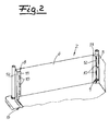
- the Fig. 2 shows in detail an inside view of the housing 2, in the direction of the left side wall 4 of the trolley.
- the vertical rails 8, 9 contain vertically aligned slots 10, which are arranged in a selected between 50 mm and 70 mm uniform grid. Preferred is a grid of about 60 mm.
- the slots 10 of the front vertical rail 8 and the slots of the housing 9 adjacent to the vertical rail 9 are arranged in mounting surfaces 11, 12, which are aligned orthogonal to each other.
- As shown in Fig. 2 extends the attachment surface 11 of the front vertical rail 8 parallel to the side wall 4 of the housing 2 while the suspension surface 12 of the rear wall 3 of the housing 2 adjacent vertical rail 9 spaced from the rear wall 3 and aligned parallel to the rear wall 3.
- the rear vertical rail 9 consists of an angle profile, which is attached to a housing corner bridging bar 13. Alternatively, the angle profile can also be attached to the rear wall 3 or to the side wall 4.
- the side wall 4 of the housing 2 has on the front side 5 in a cross-sectionally U-shaped frame profile 14.
- the free leg of the frame profile 14 can be used simultaneously as a front vertical rail.
- the slotted suspension surface 11 is integrally formed on the frame profile 14.
- the connector 7 for supporting the support 6 are formed as Einitativerbinder that can be hung without tools in the vertical rails 8, 9.
- the suspension connector 7 is made as a stamped and bent part of sheet metal and has at its ends terminal lugs 15, 16, which are in the slots 10 of the vertical rails 8, 9 can be used.
- the Fig. 3 At the associated end of the suspension connector 7 has an L-shaped angled and provided with a Einsteckschlitz terminal lug 15, which is attachable to the lower boundary of the slot 10 of the front vertical rail.
- the suspension connector 7 has a connection lug 16, which extends parallel to the side wall 4 of the housing 2 and has a width adapted to the length of the slots 10 (FIG. Fig. 4 ).
- the sheet thickness of the terminal lugs 15, 16 is matched to the gap width of the provided in the vertical rails 8, 9 slots 10 so that the terminal lugs 15, 16 in the slots 10 with a lateral clearance of less than 0.5 mm, preferably with a game between 0.1 mm and 0.3 mm are arranged. This ensures a tight fit of the suspension connector 7 on the vertical rails 8, 9.
- the suspension connector 7 has a recessed in the direction of the side wall 4 middle holding portion 17 with a support surface for the support 6 and to the holding portion 17 offset parallel end portions 18 has.
- the edition 6, z. B. a wire rack, can be hung in the suspension connector 7.
- the support 6 consists of a wire grid.
- the support can also be designed as a closed support with a flat surface, as a shell or as a basket.
- the in Fig. 1 illustrated dolly, for example, with a fixed-mounted wire grate support 6 and an extendable wire grate support 6 'equipped.
- the support protrudes approx. 200 mm from the front of the car.
- the suspension connector 7 is made as a punched and bent part of sheet metal and has at its ends terminal lugs 15, 16, which are in the slots 10 of the vertical rail 8, 9 can be used.
- a slide rail 20 is attached, preferably made of a plastic strip, for. B. made of polyethylene.
- the support 6 ' has a frame 22 formed from side parts 21 and cross members.
- profiles 23 are arranged, which surround the slide rails 20 U-shaped, so that the side part 21 is guided as a slide on the slide rail 20.
- the profile 23 may be integrally formed on the side part 21 and consist of a formed by sheet metal forming portion of the side part.
- pins 24 are fixed, which limit the sliding path of the support 6 '.
- the suspension connector 7 has at its front end an L-shaped angled and provided with a Einsteckschlitz terminal lug 15 which can be suspended in slots 10 of the front vertical rail 9.
- the suspension connector 7 has two terminal lugs 16, 16 ', which extend parallel to the side wall 4 and in spaced-apart slots 10 of the vertical rail 8 can be inserted.
- One of the two terminal lugs 16 has a width adapted to the length of the slots 10, while the other terminal lug 16 'is significantly narrower.
- the suspension connector 7 is capable of large lateral forces and tilting moments, which can occur at a loading of the extended support 6 'record.
Landscapes
- Health & Medical Sciences (AREA)
- Life Sciences & Earth Sciences (AREA)
- Engineering & Computer Science (AREA)
- Surgery (AREA)
- Public Health (AREA)
- General Health & Medical Sciences (AREA)
- Veterinary Medicine (AREA)
- Animal Behavior & Ethology (AREA)
- Biomedical Technology (AREA)
- Heart & Thoracic Surgery (AREA)
- Nuclear Medicine, Radiotherapy & Molecular Imaging (AREA)
- Medical Informatics (AREA)
- Molecular Biology (AREA)
- Nursing (AREA)
- Chemical & Material Sciences (AREA)
- Combustion & Propulsion (AREA)
- Transportation (AREA)
- Mechanical Engineering (AREA)
- Handcart (AREA)
- Housing For Livestock And Birds (AREA)
Abstract
Description
- Die Erfindung betrifft einen Transportwagen, insbesondere für Sterilgut, mit einem Fahrgestell, einem auf dem Fahrgestell angeordneten Gehäuse, das eine Rückwand sowie zwei Seitenwände aufweist und an seiner Frontseite durch eine ein- oder zweiflügelige Tür verschlossen ist, und mit mindestens einer höhenverstellbaren Auflage. Die Auflage ist auf Verbindern abgestützt, die sich parallel zu den Seitenwänden des Gehäuses erstrecken und an Vertikalschienen im Innenraum des Gehäuses befestigt sind. Der Transportwagen kann in reinen und unreinen Klinikbereichen zum sicheren und damit hygienisch einwandfreien Transport von Sterilgut verwendet werden. Die Auflage besteht häufig aus einem Drahtrost oder einem Lochblech. Unterschiedliche Ausgestaltungen der Auflage lassen den Transport und die Lagerung von Sterilgut in Körben, Siebschalen, Containern, Sterilfolienverpackungen und Einwegverpackungen zu.
- Bei einem aus der Praxis bekannten Transportwagen, von dem die Erfindung ausgeht, bestehen die Vertikalschienen aus Holmen, an denen vorstehende Stifte angeordnet sind. Die Verbinder zur Abstützung eines Rostes oder einer sonstigen Auflage weisen an ihren Enden abgewinkelte Laschen auf, wobei eine Lasche eine Bohrung und die andere Lasche eine C-förmige Ausstanzung enthält. Die Verbinder werden an ihrem einen Ende auf einen vorstehenden Zapfen der Holme aufgesteckt und an ihrem anderen Ende an einem vorstehenden Zapfen angehängt. Die Stabilität der Aufhängung ist noch verbesserungsbedürftig. Ferner besteht die Gefahr, dass Papier- oder Folienverpackungen des Sterilgutes an den vorstehenden Zapfen der Holme beschädigt werden.
- Die
DE 101 56 602 C1 offenbart einen Transportwagen insbesondere für Sterilgut, mit vertikalen Stützträgern. Die Stützträger sind mit vorzugsweise äquidistant angeordneten Ausschnitten versehen, in welche Tragbügel einhängbar sind, an denen Transportbehälter angeordnet werden können. Die Ausschnitte sind gemäß der Zeichnungen sowohl an den vorderen als auch an den hinteren vertikalen Stützträgern frontseitig angeordnet. - Ein weiterer Transportwagen, insbesondere für Sterilgut, ist in der
DE 101 55 515 A1 beschrieben. Dabei sind alle Bestandteile des Rahmens, einschließlich vertikal verlaufender Stützträger, als wenigstens einseitig offene Profile ausgeführt. Zur direkten Aufnahme von Einlegeelementen sind dabei Aussparungen in den Stützträgern vorgesehen, welche bevorzugt an den innenliegenden Schenkeln der Profil angeordnet sind. - Die Patentschrift
US 3,199,683 offenbart einen Transportwagen mit vertikalen Holmen. An jeweils zwei parallelen Innenflächen benachbarter Holme sind Schlitze zur Aufnahme von Gleitschienen vorgesehen, auf denen Bleche, Pfannen und dergleichen abgestützt werden können. - Der Erfindung liegt die Aufgabe zugrunde, einen Transportwagen für Sterilgut anzugeben, dessen Auflagen für das Sterilgut ohne Werkzeug in einem vorgegebenen Raster höhenverstellbar sind. Die Position, Anzahl sowie auch die Art der Auflagen sollen jederzeit veränderbar und austauschbar sein. Dabei sind sowohl an den Vertikalschienen als auch an den Verbindern zur Abstützung der Auflagen vorstehende Teile an denen Folien- oder Papierverpackungen des Sterilgutes beschädigt werden können, zu vermeiden.
- Gegenstand der Erfindung und Lösung dieser Aufgabe ist ein Transportwagen nach Anspruch 1.
- Erfindungsgemäß sind die Verbinder als Einhängeverbinder ausgebildet, die an ihrem einen Ende in Schlitze einer an der Frontseite des Gehäuses angeordneten Vertikalschiene und an ihrem anderen Ende in Schlitze einer zur Gehäuserückwand benachbarten Vertikalschiene eingehängt werden können. Erfindungsgemäß sind die Schlitze der frontseitigen Vertikalschiene und die Schlitze der zur Gehäuserückwand benachbarten Vertikalschiene in Einhängeflächen der Vertikalschienen angeordnet, die zueinander orthogonal ausgerichtet sind. Die Einhängefläche einer Vertikalschiene erstreckt sich somit parallel zur Rückwand, während die Einhängefläche der anderen Vertikalschiene parallel zur Seitenwand des Gehäuses ausgerichtet ist. Die Schlitze der Vertikalschienen erstrecken sich insbesondere vertikal und sind vorzugsweise mit einem zwischen 50 mm und 70 mm gewählten einheitlichen Rastermaß in den Vertikalschienen angeordnet. Besonders bevorzugt ist ein Rastermaß von etwa 60 mm.
- Gemäß einer bevorzugten Ausführung der Erfindung erstreckt sich die Einhängefläche der frontseitigen Vertikalschiene parallel zur Seitenwand des Gehäuses. Die Seitenwände des Gehäuses können an der Frontseite ein im Querschnitt U-förmiges Zargenprofil aufweisen, an welches die Einhängefläche einstückig angeformt ist. Die Schlitze in der zur Seitenwand parallelen Einhängefläche der frontseitigen Vertikalschiene legen die korrekte Lage des Verbinders fest und sichern den Verbinder gegen axiales Verschieben.
- An den Abstand, der bei der Fertigung des Gehäuses zwischen der Einhängefläche der frontseitigen Vertikalschiene und den an der Rückwand angeordneten Vertikalschienen eingehalten werden muss, werden keine besonderen Toleranzanforderungen gestellt. Die Einhängeverbinder sind in den Schlitzen der rückseitigen Vertikalschiene schwimmend gelagert. Die in Schlitzen der rückseitigen Vertikalschienen eingeführten Steckelemente geben den Einhängeverbindern seitlichen Halt und nehmen Querkräfte auf.
- Die Einhängefläche der zur Rückwand des Gehäuses benachbarten Vertikalschiene ist mit Abstand vor der Rückwand angeordnet, wobei der Abstand der Rückwand so bemessen ist, dass die den Schlitz durchfassenden Teile des Einhängeverbinders ausreichend weit überstehen können. Die rückseitige Vertikalschiene kann dabei aus einem Winkelprofil bestehen, welches an der Rückwand, einer Seitenwand oder einer die Gehäuseecke überbrückende Leiste befestigt ist.
- Vorzugsweise sind die Einhängeverbinder als Stanz- und Biegeteile aus Blech gefertigt und weisen an ihren Enden Anschlussfahnen auf, die in die Schlitze der Vertikalschienen einsetzbar sind. Die Montage ist ohne Werkzeug möglich. Die Einhängeverbinder weisen an einem Ende eine L-förmig abgewinkelte und mit einem Einsteckschlitz versehene Anschlussfahne auf, die auf die untere Berandung der Schlitze in der zugeordneten Vertikalschiene aufsteckbar ist. Die Anschlussfahne ist in die Schlitze der Einhängefläche einführbar, die sich parallel zur Seitenwand des Gehäuses erstreckt. Üblicherweise handelt es sich um die frontseitige Vertikalschiene. An ihrem anderen Ende weisen die Einhängeverbinder eine Anschlussfahne auf, die sich parallel zur Seitenwand des Gehäuses erstreckt und in die Schlitze der rückseitigen Vertikalschiene einführbar sind, deren Einhängefläche sich parallel zur Rückwand des Gehäuses erstreckt. Die Anschlussfahne des Einhängeverbinders weist eine an die Länge der Schlitze angepasste Breite auf. Die in einen Schlitz der rückseitigen Einhängeschiene eingeführte Anschlussfahne nimmt auf den Einhängeverbinder wirkende Querkräfte und Biegemomente auf und sichert den Einhängeverbinder vertikal.
- Zur Aufnahme großer Querkräfte und Kippmomente eignet sich eine Ausführung des Einhängeverbinders mit zwei Anschlussfahnen, die sich parallel zur Seitenwand erstrecken und in zueinander beabstandete Schlitze der zur Rückwand des Gehäuses benachbarten Vertikalschienen einsteckbar sind. Während eine der beiden Anschlussfahnen eine an die Länge der Schlitze angepasste Breite aufweist, ist die andere Anschlussfahne zweckmäßig deutlich schmaler ausgebildet.
- Bei allen zuvor beschriebenen Ausführungen ist die Blechstärke der Anschlussfahnen vorzugsweise auf die Spaltbreite der in den Vertikalschienen vorgesehenen Schlitze so abgestimmt, dass die Anschlussfahnen in den Schlitzen mit einem seitlichen Spiel von weniger als 0,5 mm angeordnet sind. Bevorzugt ist ein Spiel von 0,1 bis 0,3 mm. Die Montage ist trotz der engen Toleranzen problemlos. Zunächst wird der Einhängeverbinder in mindestens einen Schlitz einer an der Rückwand des Gehäuses angeordneten Vertikalschiene eingeschoben. Danach kann die Einhängeschiene mit einer seitwärts gerichteten Bewegung in einen Schlitz der frontseitigen Vertikalschiene eingehängt werden. Die Abmessungen und Materialstärke der Anschlussfahnen und die Geometrie der Schlitze können mit engen Toleranzen aufeinander abgestimmt werden, ohne dass der Montagevorgang hierdurch erschwert wird. Durch enge Toleranzen, die zwischen den Anschlussfahnen und der Geometrie der Schlitze eingehalten werden, ist der Einhängeverbinder fest und mit strammen Sitz an den Vertikalschienen befestigbar.
- Die Geometrie der Einhängeverbinder und ihre Stützflächen sind auf die Auflage abzustimmen. Die Einhängeverbinder können insbesondere einen in Richtung auf die Seitenwand zurückspringenden mittleren Halteabschnitt mit einer Stützfläche für die Auflage und dazu parallel versetzt angeordnete Endabschnitte aufweisen. Eine in den Halteabschnitt eingehängte Auflage, z. B. in Form eines Drahtrostes, eines Lochbleches, eines Korbes oder dergleichen, ist durch die in den Gehäuseinnenraum vorspringenden Endabschnitte des Einhängeverbinders lagegesichert.
- Zur Verbesserung der Formstabilität können die Einhängeverbinder an ihrem unteren Rand eine Abkantung aufweisen.
- Die an den Einhängeverbindern abgestützte Auflage kann vielfältig ausgestaltet sein. Die Auflage kann insbesondere als Drahtrost, als ebene Fläche, Schale oder als Korb ausgebildet sein, wobei die Auflage je nach Ausführung an den Einhängeverbindern aufgehängt ist oder auf vorspringenden Flächen der Einhängeverbinder aufliegen kann.
- Der Transportwagen kann erfindungsgemäß auch mit einer oder mehreren herausziehbaren Auflagen ausgestattet werden, die wie alle anderen Auflagen in dem vorgegebenen Höhenraster der Vertikalschienen variabel und ohne Werkzeug verstellt werden können. Für eine herausziehbare Auflage werden Einhängeverbinder verwendet, an denen jeweils eine Gleitschiene befestigt ist. Die Auflage weist Seitenteile auf, die an den Gleitschienen zwischen Anschlagelementen verschiebbar geführt sind. Vorzugsweise bestehen die Gleitschienen aus Kunststoffleisten und sind an die Seitenteile der Auflage Profile angeschlossen oder durch Blechumformung einteilig angeformt, welche die Gleitschienen U-förmig umgreifen. An der Unterseite der Gleitschienen können Zapfen befestigt sein, welche den Schiebeweg der Auflage begrenzen. Um Sterilgüter auf den Auflagen abzustellen oder von der Auflage zu entnehmen, kann die Auflage um bis zu einem Drittel aus dem Gehäuse des Transportwagens herausgezogen werden. Bei einer standardmäßigen Gehäusetiefe von 600 mm ragt die Auflage somit ca. 200 mm nach vorne aus dem Wagen. Dies erleichtert die Handhabung beachtlich.
- Die Auflage weist zweckmäßig einen aus Seitenteilen und Querträgern gebildeten Rahmen auf. Die Auflagefläche kann aus einem Drahtrost, einem Lochblech oder dergleichen bestehen.
- Der erfindungsgemäße Transportwagen kann als geschlossener Sterilguttransportwagen eingesetzt werden, dessen Gehäuse aus einem stabilen, selbsttragenden Korpus aus Edelstahl gefertigt ist. An seiner Frontseite weist der Wagen eine ein- oder zweiflügelige Tür auf, die mit einem Schwenkwinkel von bis zu 270° schwenkbar sind. Mit einem vorgegebenen Rastermaß, welches durch die Anordnung der Schlitze der Vertikalschienen vorgegeben ist, können Auflagen eingesetzt werden, wobei Drahtrostauflagen, geschlossene Auflagen und sonstige Auflagen aus einem Standardregalprogramm verwendet werden können. Die Auflagen lassen sich einfach und schnell in die Einhängeverbinder einhängen und wieder entnehmen. Der Innenraum des Transportwagens ist glatt und lässt sich dadurch gut reinigen. Durch Versetzen der Einhängeverbinder können die Auflagen in einem vorgegebenen Raster, welches durch die Anordnung der Schlitze der Vertikalschienen festgelegt ist, variabel versetzt werden. Dadurch sind sowohl die Position, Anzahl als auch die Art der Auflagen jederzeit veränderbar und austauschbar. Insbesondere kann der Transportwagen auch mit einem oder mehreren herausziehbaren Auflagen ausgestattet werden.
- Im Folgenden wird die Erfindung anhand von Ausführungsbeispielen erläutert. Es zeigen schematisch:
- Fig.1
- einen geöffneten Transportwagen für Sterilgut mit zwei höhenverstellbaren Auflagen,
- Fig. 2
- im Ausschnitt eine Ansicht des Innenraums des in
Fig. 1 dargestellten Transportwagens, - Fig. 3
- die Befestigung eines Einhängeverbinders an der Frontseite des in
Fig. 1 dargestellten Transportwagens, - Fig. 4
- die Befestigung eines Einhängeverbinders an der Rückwand des in
Fig. 1 dargestellten Transportwagens, - Fig. 5
- eine unterseitige Ansicht eines Einhängeverbinders für eine verschiebbare Auflage,
- Fig. 6
- die Befestigung des in
Fig. 5 dargestellten Einhängeverbinders an der Rückwand des Transportwagens, - Fig. 7
- eine Einzelteilzeichnung des in den
Fig. 5 und6 dargestellten Einhängeverbinders. - In
Fig. 1 ist ein Transportwagen für Sterilgut dargestellt, der in reinen und unreinen Klinikbereichen zum sicheren und hygienisch einwandfreien Transport von Sterilgut verwendet werden kann, und zwar sowohl bei der Versorgung als auch bei der Entsorgung. Der Transportwagen besteht in seinem grundsätzlichen Aufbau aus einem Fahrgestell 1 und einem auf dem Fahrgestell angeordneten kastenförmigem Gehäuse 2, das eine Rückwand 3 sowie zwei Seitenwände 4 aufweist und an seiner Frontseite 5 durch eine ein- oder zweiflügelige Tür verschlossen ist. DieFig. 1 zeigt den geöffneten Transportwagen. Der Transportwagen ist mit einer oder mehreren höhenverstellbaren Auflagen 6, 6' ausgestattet. Die Auflagen 6, 6' sind auf Verbindern 7 abgestützt, die an Vertikalschienen 8, 9 im Innenraum des Gehäuses 2 befestigt sind und sich parallel zu den Seitenwänden 4 des Gehäuses 2 erstrecken. - Die
Fig. 2 zeigt im Ausschnitt eine innenseitige Ansicht des Gehäuses 2, und zwar in der Blickrichtung auf die linke Seitenwand 4 des Transportwagens. Die Vertikalschienen 8, 9 enthalten vertikal ausgerichtete Schlitze 10, die in einem zwischen 50 mm und 70 mm gewählten einheitlichen Rastermaß angeordnet sind. Bevorzugt ist ein Rastermaß von ca. 60 mm. Die Schlitze 10 der frontseitigen Vertikalschiene 8 und die Schlitze der zur Gehäuserückwand benachbarten Vertikalschiene 9 sind in Einhängeflächen 11, 12 angeordnet, die zueinander orthogonal ausgerichtet sind. Gemäß der Darstellung inFig. 2 erstreckt sich die Einhängefläche 11 der frontseitigen Vertikalschiene 8 parallel zur Seitenwand 4 des Gehäuses 2 während die Einhängefläche 12 der zur Rückwand 3 des Gehäuses 2 benachbarten Vertikalschiene 9 mit Abstand vor der Rückwand 3 angeordnet und parallel zur Rückwand 3 ausgerichtet ist. Die rückseitige Vertikalschiene 9 besteht aus einem Winkelprofil, welches an einer die Gehäuseecke überbrückenden Leiste 13 befestigt ist. Alternativ kann das Winkelprofil auch an der Rückwand 3 oder an der Seitenwand 4 befestigt sein. Die Seitenwand 4 des Gehäuses 2 weist an der Frontseite 5 ein im Querschnitt U-förmiges Zargenprofil 14 auf. Der freie Schenkel des Zargenprofils 14 kann gleichzeitig als frontseitige Vertikalschiene genutzt werden. Die geschlitzte Einhängefläche 11 ist an das Zargenprofil 14 einstückig angeformt. Alternativ besteht selbstverständlich auch die Möglichkeit, die Vertikalschiene 8 als Winkelprofil auszubilden und an dem Zargenprofil 14 zu befestigen. - Die Verbinder 7 zur Abstützung der Auflage 6 sind als Einhängeverbinder ausgebildet, die ohne Werkzeug in die Vertikalschienen 8, 9 eingehängt werden können. In den
Fig. 3 und4 ist die Befestigung eines Einhängeverbinders an der frontseitigen Vertikalschiene 8 und an der zur Rückwand benachbarten Vertikalschiene 9 dargestellt. Der Einhängeverbinder 7 ist als Stanz- und Biegeteil aus Blech gefertigt und weist an seinen Enden Anschlussfahnen 15, 16 auf, die in die Schlitze 10 der Vertikalschienen 8, 9 einsetzbar sind. DieFig. 3 zeigt die Befestigung des Einhängeverbinders 7 an der frontseitigen Vertikalschiene 8. An dem zugeordneten Ende weist der Einhängeverbinder 7 eine L-förmig abgewinkelte und mit einem Einsteckschlitz versehene Anschlussfahne 15 auf, die auf die untere Berandung des Schlitzes 10 der frontseitigen Vertikalschiene aufsteckbar ist. An ihrem anderen Ende weist der Einhängeverbinder 7 eine Anschlussfahne 16 auf, die sich parallel zur Seitenwand 4 des Gehäuses 2 erstreckt und eine an die Länge der Schlitze 10 angepasste Breite aufweist (Fig. 4 ). Die Blechstärke der Anschlussfahnen 15, 16 ist auf die Spaltbreite der in den Vertikalschienen 8, 9 vorgesehenen Schlitze 10 so abgestimmt, dass die Anschlussfahnen 15, 16 in den Schlitzen 10 mit einem seitlichen Spiel von weniger als 0,5 mm, vorzugsweise mit einem Spiel zwischen 0,1 mm und 0,3 mm, angeordnet sind. Dadurch ist ein fester Sitz des Einhängeverbinders 7 an den Vertikalschienen 8, 9 gewährleistet. - Den Darstellungen in den
Fig. 3 und4 ist auch zu entnehmen, dass der Einhängeverbinder 7 einen in Richtung auf die Seitenwand 4 zurückspringenden mittleren Halteabschnitt 17 mit einer Stützfläche für die Auflage 6 und zu dem Halteabschnitt 17 parallel versetzt angeordnete Endabschnitte 18 aufweist. Die Auflage 6, z. B. eine Drahtrostauflage, kann in den Einhängeverbinder 7 eingehängt werden. Zur Verbesserung der Formstabilität weist der Einhängeverbinder 7 ferner an seinem unteren Rand eine Abkantung 19 auf. Im Ausführungsbeispiel besteht die Auflage 6 aus einem Drahtrost. Die Auflage kann auch als geschlossene Auflage mit einer ebenen Fläche, als Schale oder als Korb ausgebildet sein. - Der in
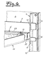
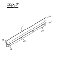
Fig. 1 dargestellte Transportwagen ist beispielsweise mit einer fest eingehängten Drahtrostauflage 6 und einer ausziehbaren Drahtrostauflage 6' ausgestattet. Die ausziehbare Drahtrostauflage 6' kann um ein Drittel ausgezogen werden. Bei einer Tiefe von ca. 600 mm ragt die Auflage somit ca. 200 mm vorne aus dem Wagen. Ein Einhängeverbinder 7 für eine ausziehbare Auflage 6' ist in denFig. 5 bis 7 dargestellt. Der Einhängeverbinder 7 ist als Stanz- und Biegeteil aus Blech gefertigt und weist an seinen Enden Anschlussfahnen 15, 16 auf, die in die Schlitze 10 der Vertikalschiene 8, 9 einsetzbar sind. An dem Einhängeverbinder 7 ist eine Gleitschiene 20 befestigt, die vorzugsweise aus einer Kunststoffleiste, z. B. aus Polyethylen, besteht. Die Auflage 6' weist einen aus Seitenteilen 21 und Querträgern gebildeten Rahmen 22 auf. An den Seitenteilen 21 sind Profile 23 angeordnet, welche die Gleitschienen 20 U-förmig umgreifen, so dass das Seitenteil 21 als Schlitten an der Gleitschiene 20 geführt ist. Das Profil 23 kann einteilig an dem Seitenteil 21 angeformt sein und aus einem durch Blechumformung gebildeten Abschnitt des Seitenteils bestehen. An der Unterseite der Gleitschiene 20 sind Zapfen 24 befestigt, welche den Schiebeweg der Auflage 6' begrenzen. - Der Einhängeverbinder 7 weist an seinem vorderen Ende eine L-förmig abgewinkelte und mit einem Einsteckschlitz versehene Anschlussfahne 15 auf, die in Schlitze 10 der frontseitigen Vertikalschiene 9 eingehängt werden kann. An seinem anderen Ende weist der Einhängeverbinder 7 zwei Anschlussfahnen 16, 16' auf, die sich parallel zur Seitenwand 4 erstrecken und in zueinander beabstandete Schlitze 10 der Vertikalschiene 8 einsteckbar sind. Eine der beiden Anschlussfahnen 16 weist eine an die Länge der Schlitze 10 angepasste Breite auf, während die andere Anschlussfahne 16' deutlich schmaler ausgebildet ist. Der Einhängeverbinder 7 ist in der Lage, große Querkräfte und Kippmomente, die bei einer Beladung der ausgezogenen Auflage 6' auftreten können, aufzunehmen.
Claims (20)
- Transportwagen, insbesondere für Sterilgut mit
einem Fahrgestell (1),
einem auf dem Fahrgestell (1) angeordneten Gehäuse (2), das eine Rückwand (3) sowie zwei Seitenwände (4) aufweist und an seiner Frontseite (5) durch eine ein- oder zweiflügelige Tür verschlossen ist, und
mindestens einer höhenverstellbaren Auflage (6),
wobei die Auflage (6) auf Verbindern (7) abgestützt ist, die an Vertikalschienen (8, 9) im Innenraum des Gehäuses (2) befestigt sind und sich parallel zu den Seitenwänden (4) des Gehäuses (2) erstrecken, wobei die Verbinder (7) als Einhängeverbinder ausgebildet sind, die an ihrem einen Ende in Schlitze (10) einer an der Frontseite (5) des Gehäuses angeordneten Vertikalschiene (8) und an ihrem anderen Ende in Schlitze (10) einer zur Gehäuserückwand (4) benachbarten Vertikalschiene (9) eingehängt werden können, dadurch gekennzeichnet, dass die Schlitze (10) der frontseitigen Vertikalschiene (8) und die Schlitze (10) der zur Gehäuserückwand benachbarten Vertikalschiene (9) in Einhängeflächen (11, 12) der Vertikalschienen (8, 9) angeordnet sind, die zueinander orthogonal ausgerichtet sind. - Transportwagen nach Anspruch 1, dadurch gekennzeichnet, dass die Schlitze (10) der Vertikalschienen (8, 9) vertikal ausgerichtet sind.
- Transportwagen nach Anspruch 1 oder 2, dadurch gekennzeichnet, dass die Einhängefläche (11) der frontseitigen Vertikalschiene (8) sich parallel zur Seitenwand (4) des Gehäuses (2) erstreckt.
- Transportwagen nach Anspruch 3, dadurch gekennzeichnet, dass die Seitenwände (4) des Gehäuses (2) an der Frontseite (5) ein im Querschnitt U-förmiges Zargenprofil (14) aufweisen und dass die Einhängefläche (11) an das Zargenprofil (14) einstückig angeformt ist.
- Transportwagen nach einem der Ansprüche 1 bis 4, dadurch gekennzeichnet, dass die Einhängefläche (11) der zur Rückwand (4) des Gehäuses (2) benachbarten rückseitigen Vertikalschiene (9) mit Abstand vor der Rückwand (4) angeordnet ist.
- Transportwagen nach Anspruch 5, dadurch gekennzeichnet, dass die rückseitige Vertikalschiene (9) aus einem Winkelprofil besteht, welches an der Rückwand (13), einer Seitenwand (4) oder einer die Gehäuseecke überbrückenden Leiste (13) befestigt ist.
- Transportwagen nach einem der Ansprüche 1 bis 6, dadurch gekennzeichnet, dass die Einhängeverbinder (7) als Stanz- und Biegeteile aus Blech gefertigt sind und an ihren Enden Anschlussfahnen (15, 16) aufweisen, die in die Schlitze (10) der Vertikalschienen (8, 9) ohne Werkzeug einsetzbar sind.
- Transportwagen nach Anspruch 7, dadurch gekennzeichnet, dass die Einhängeverbinder (7) an einem Ende eine L-förmig abgewinkelte und mit einem Einsteckschlitz versehene Anschlussfahne (15) aufweisen, die auf die untere Berandung der Schlitze (10) in den Vertikalschienen (8) aufsteckbar ist.
- Transportwagen nach Anspruch 8, dadurch gekennzeichnet, dass die Einhängeverbinder (7) an ihrem anderen Ende eine Anschlussfahne (16) aufweisen, die sich parallel zur Seitenwand (4) des Gehäuses (2) erstreckt und eine an die Länge der Schlitze (10) angepasste Breite aufweist.
- Transportwagen nach Anspruch 8, dadurch gekennzeichnet, dass die Einhängeverbinder (7) an ihrem anderen Ende zwei Anschlussfahnen (16, 16') aufweisen, die sich parallel zur Seitenwand (4) erstrecken und in zueinander beabstandete Schlitze (10) der Vertikalschiene (9) einsteckbar sind.
- Transportwagen nach Anspruch 10, dadurch gekennzeichnet, dass eine der beiden Anschlussfahnen (16) eine an die Länge der Schlitze (10) angepasste Breite aufweist und die andere Anschlussfahne (16') schmaler ausgebildet ist.
- Transportwagen nach einem der Ansprüche 7 bis 11, dadurch gekennzeichnet, dass die Blechstärke der Anschlussfahnen (15, 16) auf die Spaltbreite der in den Vertikalschienen (8, 9) vorgesehenen Schlitze (10) so abgestimmt ist, dass die Anschlussfahnen (15, 16) in den Schlitzen (10) mit einem seitlichen Spiel von weniger als 0,5 mm angeordnet sind.
- Transportwagen nach einem der Ansprüche 1 bis 12, dadurch gekennzeichnet, dass die Schlitze (10) mit einem zwischen 50 mm und 70 mm gewählten einheitlichen Rastermaß in den Vertikalschienen (8, 9) angeordnet sind.
- Transportwagen nach einem der Ansprüche 1 bis 13, dadurch gekennzeichnet, dass die Einhängeverbinder (7) einen in Richtung auf die Seitenwand (4) zurückspringenden mittleren Halteabschnitt (17) mit einer Stützfläche für die Auflage (6) und zu dem Halteabschnitt parallel versetzt angeordnete Endabschnitte (18) aufweisen.
- Transportwagen nach einem der Ansprüche 1 bis 14, dadurch gekennzeichnet, dass die Einhängeverbinder (7) an ihrem unteren Rand eine Abkantung (19) zur Verbesserung der Formstabilität aufweisen.
- Transportwagen nach einem der Ansprüche 1 bis 15, dadurch gekennzeichnet, dass die Auflage (6) als Drahtrost, ebene Fläche, Schale oder als Korb ausgebildet ist und an den Einhängeverbindern (7) aufgehängt ist oder auf vorspringenden Flächen der Einhängeverbinder aufliegt.
- Transportwagen nach einem der Ansprüche 1 bis 14, dadurch gekennzeichnet, dass an den Einhängeverbindern (7) eine Gleitschiene (20) befestigt ist und dass die Auflage (6') Seitenteile (21) aufweist, die an den Gleitschienen (20) zwischen Anschlagelementen verschiebbar geführt sind.
- Transportwagen nach Anspruch 17, dadurch gekennzeichnet, dass die Gleitschienen (20) aus Kunststoffleisten bestehen und dass an die Seitenteile (21) Profile (23) angeschlossen oder angeformt sind, welche die Gleitschienen (20) U-förmig umgreifen.
- Transportwagen nach Anspruch 18, dadurch gekennzeichnet, dass an der Unterseite der Gleitschienen (20) Zapfen (24) befestigt sind, welche den Schiebeweg der Auflage (6') begrenzen.
- Transportwagen nach einem der Ansprüche 17 bis 19, dadurch gekennzeichnet, dass die Auflage (6') einen aus den Seitenteilen (21) und Querträgern gebildeten Rahmen (22) aufweist.
Applications Claiming Priority (1)
| Application Number | Priority Date | Filing Date | Title |
|---|---|---|---|
| DE102011055413A DE102011055413B3 (de) | 2011-11-16 | 2011-11-16 | Transportwagen, insbesondere für Sterilgut |
Publications (3)
| Publication Number | Publication Date |
|---|---|
| EP2594453A2 true EP2594453A2 (de) | 2013-05-22 |
| EP2594453A3 EP2594453A3 (de) | 2015-01-14 |
| EP2594453B1 EP2594453B1 (de) | 2018-05-30 |
Family
ID=47088365
Family Applications (1)
| Application Number | Title | Priority Date | Filing Date |
|---|---|---|---|
| EP12192290.0A Active EP2594453B1 (de) | 2011-11-16 | 2012-11-12 | Transportwagen, insbesondere für Sterilgut |
Country Status (3)
| Country | Link |
|---|---|
| US (1) | US20140049014A1 (de) |
| EP (1) | EP2594453B1 (de) |
| DE (1) | DE102011055413B3 (de) |
Cited By (4)
| Publication number | Priority date | Publication date | Assignee | Title |
|---|---|---|---|---|
| CN103932804A (zh) * | 2014-05-04 | 2014-07-23 | 苏州博讯仪器有限公司 | 一种多功能仪器车 |
| CN105599796A (zh) * | 2016-01-19 | 2016-05-25 | 张家港市旭骏机械部件有限公司 | 一种货物周转推车 |
| CN113212515A (zh) * | 2021-05-25 | 2021-08-06 | 深圳市全景世纪科技有限公司 | 一种多功能移动黑匣 |
| CN113442979A (zh) * | 2021-07-30 | 2021-09-28 | 中国人民解放军联勤保障部队第九八〇医院 | 一种消毒供应室运转车 |
Families Citing this family (24)
| Publication number | Priority date | Publication date | Assignee | Title |
|---|---|---|---|---|
| CN104095686A (zh) * | 2013-04-09 | 2014-10-15 | 成都嘉逸科技有限公司 | 一种防菌手术器械车 |
| US20170367503A1 (en) * | 2013-07-18 | 2017-12-28 | Bedgear, Llc | Pillow display cart |
| US9386868B2 (en) | 2013-10-24 | 2016-07-12 | Bedgear, Llc | Pillow napkin dispensing system and method |
| WO2016048153A1 (en) * | 2014-09-26 | 2016-03-31 | Hoza B.V. | Shelf for a rolling container, rolling container provided therewith and method therefor |
| NL2013651B1 (nl) * | 2014-09-26 | 2016-10-03 | Hoza B V | Legbord voor een rolcontainer, rolcontainer voorzien daarvan en werkwijze daarvoor. |
| WO2016056912A1 (en) * | 2014-10-10 | 2016-04-14 | Hoza B.V. | Composite shelf for a rolling container, rolling container provided therewith and method therefor |
| CN104688464A (zh) * | 2015-02-13 | 2015-06-10 | 徐艳松 | 护理身体清洗擦拭装置 |
| CN104800023A (zh) * | 2015-05-18 | 2015-07-29 | 徐秀 | 一种医院住院部用输液瓶集体运输车 |
| CN106184305B (zh) * | 2015-11-18 | 2018-02-06 | 哈尔滨圣泰生物制药有限公司 | 一种口服液车间物料运输车 |
| NL2015838B1 (en) * | 2015-11-23 | 2017-06-07 | Container Centralen As | Wheeled container and elongated support profile to be used therein. |
| CN105383528A (zh) * | 2015-12-14 | 2016-03-09 | 重庆志成机械有限公司 | 一种可调式转运斗 |
| PL3407922T3 (pl) | 2016-01-29 | 2022-02-14 | Turbett Surgical, Inc. | Sposób załadowywania sterylizatora ładowanego z poziomu podłogi |
| US10188477B1 (en) * | 2017-10-10 | 2019-01-29 | Neonatal Product Group, Inc. | Mobile medical cart |
| AU201716528S (en) * | 2017-10-27 | 2017-11-15 | Comfortel Furniture Pty Ltd | Trolley |
| USD898319S1 (en) * | 2018-11-07 | 2020-10-06 | Inter Ikea Systems B.V. | Trolley table |
| USD901122S1 (en) * | 2019-04-11 | 2020-11-03 | Lakeshore Equipment Company | Cart |
| GB2584477B (en) | 2019-06-06 | 2021-09-22 | Keymed Medical & Industrial Equipment Ltd | Mounting system for a medical workstation |
| DE102020111731A1 (de) | 2020-04-29 | 2021-11-04 | Alfred Kärcher SE & Co. KG | Reinigungswagen |
| USD988029S1 (en) | 2020-06-01 | 2023-06-06 | Keymed (Medical & Industrial Equipment) Ltd. | Workstation mounting apparatus |
| IT202100003341A1 (it) * | 2021-02-15 | 2022-08-15 | Antares Vision S P A | Carrello per la distribuzione di medicinali |
| DE102021126620A1 (de) | 2021-10-14 | 2023-04-20 | Wanzl GmbH & Co. KGaA | Stapelbarer Transportwagen |
| DE102022111697A1 (de) | 2022-05-10 | 2023-11-16 | Aesculap Ag | Transportvorrichtung und Verwendung derselben zum Transport zumindest eines Sterilgutbehälters |
| US20230399040A1 (en) * | 2022-06-10 | 2023-12-14 | Eirik Skeid | Shelf System, Intercage Locking System, and Rolling Storage Module with Lockable Brake for Cage |
| US20240140705A1 (en) * | 2022-11-01 | 2024-05-02 | Caleb Kelly | Mobile customizable inventory management apparatus |
Family Cites Families (18)
| Publication number | Priority date | Publication date | Assignee | Title |
|---|---|---|---|---|
| US1571601A (en) * | 1924-04-07 | 1926-02-02 | Gunn Furniture Company | Bookcase construction |
| US2661993A (en) * | 1948-10-06 | 1953-12-08 | Robert A Little | Sectional furniture |
| US2746109A (en) * | 1951-08-23 | 1956-05-22 | Globe Wernicke Co | Structural fastener elements |
| US2999599A (en) * | 1958-09-02 | 1961-09-12 | Jentzen Miller Company | Display shelving |
| US3199683A (en) * | 1963-12-30 | 1965-08-10 | Dohrmann Hotel Supply Co | Portable and adjustable rack for supporting pans |
| US3675955A (en) * | 1970-03-23 | 1972-07-11 | Regis Mfg Co | Cabinet bracket |
| US3999775A (en) * | 1975-08-07 | 1976-12-28 | Metropolitan Wire Corporation | Rollable cart |
| DE3119475C2 (de) * | 1981-05-15 | 1984-04-19 | Eisenwerk Künstler KG, 8750 Aschaffenburg | Bausatz für Regale |
| US4846537A (en) * | 1982-03-04 | 1989-07-11 | Metropolitan Wire Corporation | Surgical case cart |
| FR2579431B1 (fr) * | 1985-03-28 | 1988-02-05 | Bastiani Jacques | Rayonnage metallique automontable embouti |
| FR2593047B1 (fr) * | 1986-01-20 | 1992-10-02 | Albadecor Sa | Elements pour la presentation et le stockage de produits sur gondoles standard. |
| DE3619262A1 (de) * | 1986-06-07 | 1987-12-10 | Cordes Werner | Transportwagen |
| JP2604284B2 (ja) * | 1991-04-25 | 1997-04-30 | 三洋電機株式会社 | ショ−ケ−スの棚装置 |
| FR2695814B1 (fr) * | 1992-09-21 | 1994-12-09 | Mc International | Dispositif modulaire pour l'exposition à la vente de denrées alimentaires. |
| US5797503A (en) * | 1995-04-21 | 1998-08-25 | Metro Industries, Inc. | Modular storage system with an active storage level feature |
| DE10155515A1 (de) * | 2001-11-13 | 2003-05-28 | Metallverarbeitung Koegel Gmbh | Transporteinrichtung für Sterilgut |
| DE10156602C1 (de) * | 2001-11-17 | 2003-08-28 | Blanco Gmbh & Co Kg | Transportsystem |
| US8505933B2 (en) * | 2009-11-30 | 2013-08-13 | Gebhardt Transport- Und Lagersysteme Gmbh | Roll container with insert bases |
-
2011
- 2011-11-16 DE DE102011055413A patent/DE102011055413B3/de active Active
-
2012
- 2012-11-09 US US13/673,051 patent/US20140049014A1/en not_active Abandoned
- 2012-11-12 EP EP12192290.0A patent/EP2594453B1/de active Active
Cited By (6)
| Publication number | Priority date | Publication date | Assignee | Title |
|---|---|---|---|---|
| CN103932804A (zh) * | 2014-05-04 | 2014-07-23 | 苏州博讯仪器有限公司 | 一种多功能仪器车 |
| CN105599796A (zh) * | 2016-01-19 | 2016-05-25 | 张家港市旭骏机械部件有限公司 | 一种货物周转推车 |
| CN113212515A (zh) * | 2021-05-25 | 2021-08-06 | 深圳市全景世纪科技有限公司 | 一种多功能移动黑匣 |
| CN113212515B (zh) * | 2021-05-25 | 2022-08-12 | 深圳市金蚁软件科技有限公司 | 一种多功能移动黑匣 |
| CN113442979A (zh) * | 2021-07-30 | 2021-09-28 | 中国人民解放军联勤保障部队第九八〇医院 | 一种消毒供应室运转车 |
| CN113442979B (zh) * | 2021-07-30 | 2022-07-01 | 中国人民解放军联勤保障部队第九八〇医院 | 一种消毒供应室运转车 |
Also Published As
| Publication number | Publication date |
|---|---|
| US20140049014A1 (en) | 2014-02-20 |
| DE102011055413B3 (de) | 2012-11-22 |
| EP2594453A3 (de) | 2015-01-14 |
| EP2594453B1 (de) | 2018-05-30 |
Similar Documents
| Publication | Publication Date | Title |
|---|---|---|
| DE102011055413B3 (de) | Transportwagen, insbesondere für Sterilgut | |
| EP2122278B1 (de) | Kältegerät mit an einer schiene aufgehängten fachböden | |
| EP2403379B1 (de) | Befestigungsanordnung | |
| EP2327601A2 (de) | Stapelbarer Rollbehälter mit Einschubböden | |
| EP3556261A1 (de) | Draht-etage für einen verkaufstisch oder ein regalsystem | |
| DE102017000851B4 (de) | Flexibles Konsolensystem für medizinische Geräte | |
| AT520691B1 (de) | Führungssystem | |
| EP2324732B1 (de) | Lagerregal, insbesondere automatisches Kleinteilelager | |
| EP2844108B1 (de) | Haltevorrichtung für ein tragelement eines schrankes sowie kühl-, gefrierschrank oder weinlagerungsschrank | |
| EP0582780B1 (de) | Möbel mit Tragteilen für in den Innenraum des Möbels einbringbare Zwischenböden | |
| DE102011055414B4 (de) | Einschubrahmen, insbesondere für Transportwagen | |
| EP4286749A1 (de) | Schnellbefestigungssystem für einen teleskopauszug | |
| EP3947105B1 (de) | Warenkorb | |
| EP3758552B1 (de) | Fachboden und fachbodenanordnung | |
| DE102009056363B3 (de) | Stapelbarer Rollbehälter mit Einschubböden | |
| DE10057619B4 (de) | Auszugssystem | |
| DE10320158A1 (de) | Backwagenrost für Backöfen | |
| DE29720097U1 (de) | Kühlschranktür | |
| EP2161505A2 (de) | Gitter zur Auflage von Zubereitungsgut sowie Kochgerät mit einem Gitter | |
| CH685976A5 (de) | Traggestell. | |
| EP0047943A2 (de) | Zerlegbarer winkelförmiger Regalständer | |
| DE202009016204U1 (de) | Stapelbarer Rollbehälter mit Einschubböden | |
| DE29621573U1 (de) | Haltesystem für Utensilien | |
| DE102014106539A1 (de) | Traverse für einen Schrank | |
| DE202008013618U1 (de) | Universaltransportwagen, insbesondere für Krankenhäuser, Pflegeheime oder ähnliche Einrichtungen |
Legal Events
| Date | Code | Title | Description |
|---|---|---|---|
| PUAI | Public reference made under article 153(3) epc to a published international application that has entered the european phase |
Free format text: ORIGINAL CODE: 0009012 |
|
| AK | Designated contracting states |
Kind code of ref document: A2 Designated state(s): AL AT BE BG CH CY CZ DE DK EE ES FI FR GB GR HR HU IE IS IT LI LT LU LV MC MK MT NL NO PL PT RO RS SE SI SK SM TR |
|
| AX | Request for extension of the european patent |
Extension state: BA ME |
|
| PUAL | Search report despatched |
Free format text: ORIGINAL CODE: 0009013 |
|
| AK | Designated contracting states |
Kind code of ref document: A3 Designated state(s): AL AT BE BG CH CY CZ DE DK EE ES FI FR GB GR HR HU IE IS IT LI LT LU LV MC MK MT NL NO PL PT RO RS SE SI SK SM TR |
|
| AX | Request for extension of the european patent |
Extension state: BA ME |
|
| RIC1 | Information provided on ipc code assigned before grant |
Ipc: A61G 12/00 20060101ALI20141209BHEP Ipc: B62B 3/00 20060101AFI20141209BHEP Ipc: A61B 19/02 20060101ALI20141209BHEP |
|
| 17P | Request for examination filed |
Effective date: 20150714 |
|
| RBV | Designated contracting states (corrected) |
Designated state(s): AL AT BE BG CH CY CZ DE DK EE ES FI FR GB GR HR HU IE IS IT LI LT LU LV MC MK MT NL NO PL PT RO RS SE SI SK SM TR |
|
| GRAP | Despatch of communication of intention to grant a patent |
Free format text: ORIGINAL CODE: EPIDOSNIGR1 |
|
| RIC1 | Information provided on ipc code assigned before grant |
Ipc: A61G 12/00 20060101ALI20171121BHEP Ipc: B62B 3/00 20060101AFI20171121BHEP |
|
| INTG | Intention to grant announced |
Effective date: 20171219 |
|
| GRAS | Grant fee paid |
Free format text: ORIGINAL CODE: EPIDOSNIGR3 |
|
| GRAA | (expected) grant |
Free format text: ORIGINAL CODE: 0009210 |
|
| AK | Designated contracting states |
Kind code of ref document: B1 Designated state(s): AL AT BE BG CH CY CZ DE DK EE ES FI FR GB GR HR HU IE IS IT LI LT LU LV MC MK MT NL NO PL PT RO RS SE SI SK SM TR |
|
| REG | Reference to a national code |
Ref country code: GB Ref legal event code: FG4D Free format text: NOT ENGLISH |
|
| REG | Reference to a national code |
Ref country code: CH Ref legal event code: EP |
|
| REG | Reference to a national code |
Ref country code: AT Ref legal event code: REF Ref document number: 1003313 Country of ref document: AT Kind code of ref document: T Effective date: 20180615 |
|
| REG | Reference to a national code |
Ref country code: DE Ref legal event code: R096 Ref document number: 502012012761 Country of ref document: DE |
|
| REG | Reference to a national code |
Ref country code: IE Ref legal event code: FG4D Free format text: LANGUAGE OF EP DOCUMENT: GERMAN |
|
| REG | Reference to a national code |
Ref country code: NL Ref legal event code: MP Effective date: 20180530 |
|
| REG | Reference to a national code |
Ref country code: LT Ref legal event code: MG4D |
|
| PG25 | Lapsed in a contracting state [announced via postgrant information from national office to epo] |
Ref country code: FI Free format text: LAPSE BECAUSE OF FAILURE TO SUBMIT A TRANSLATION OF THE DESCRIPTION OR TO PAY THE FEE WITHIN THE PRESCRIBED TIME-LIMIT Effective date: 20180530 Ref country code: NO Free format text: LAPSE BECAUSE OF FAILURE TO SUBMIT A TRANSLATION OF THE DESCRIPTION OR TO PAY THE FEE WITHIN THE PRESCRIBED TIME-LIMIT Effective date: 20180830 Ref country code: BG Free format text: LAPSE BECAUSE OF FAILURE TO SUBMIT A TRANSLATION OF THE DESCRIPTION OR TO PAY THE FEE WITHIN THE PRESCRIBED TIME-LIMIT Effective date: 20180830 Ref country code: LT Free format text: LAPSE BECAUSE OF FAILURE TO SUBMIT A TRANSLATION OF THE DESCRIPTION OR TO PAY THE FEE WITHIN THE PRESCRIBED TIME-LIMIT Effective date: 20180530 Ref country code: CY Free format text: LAPSE BECAUSE OF FAILURE TO SUBMIT A TRANSLATION OF THE DESCRIPTION OR TO PAY THE FEE WITHIN THE PRESCRIBED TIME-LIMIT Effective date: 20180530 Ref country code: ES Free format text: LAPSE BECAUSE OF FAILURE TO SUBMIT A TRANSLATION OF THE DESCRIPTION OR TO PAY THE FEE WITHIN THE PRESCRIBED TIME-LIMIT Effective date: 20180530 Ref country code: SE Free format text: LAPSE BECAUSE OF FAILURE TO SUBMIT A TRANSLATION OF THE DESCRIPTION OR TO PAY THE FEE WITHIN THE PRESCRIBED TIME-LIMIT Effective date: 20180530 |
|
| PG25 | Lapsed in a contracting state [announced via postgrant information from national office to epo] |
Ref country code: LV Free format text: LAPSE BECAUSE OF FAILURE TO SUBMIT A TRANSLATION OF THE DESCRIPTION OR TO PAY THE FEE WITHIN THE PRESCRIBED TIME-LIMIT Effective date: 20180530 Ref country code: RS Free format text: LAPSE BECAUSE OF FAILURE TO SUBMIT A TRANSLATION OF THE DESCRIPTION OR TO PAY THE FEE WITHIN THE PRESCRIBED TIME-LIMIT Effective date: 20180530 Ref country code: HR Free format text: LAPSE BECAUSE OF FAILURE TO SUBMIT A TRANSLATION OF THE DESCRIPTION OR TO PAY THE FEE WITHIN THE PRESCRIBED TIME-LIMIT Effective date: 20180530 Ref country code: GR Free format text: LAPSE BECAUSE OF FAILURE TO SUBMIT A TRANSLATION OF THE DESCRIPTION OR TO PAY THE FEE WITHIN THE PRESCRIBED TIME-LIMIT Effective date: 20180831 |
|
| PG25 | Lapsed in a contracting state [announced via postgrant information from national office to epo] |
Ref country code: NL Free format text: LAPSE BECAUSE OF FAILURE TO SUBMIT A TRANSLATION OF THE DESCRIPTION OR TO PAY THE FEE WITHIN THE PRESCRIBED TIME-LIMIT Effective date: 20180530 |
|
| PG25 | Lapsed in a contracting state [announced via postgrant information from national office to epo] |
Ref country code: EE Free format text: LAPSE BECAUSE OF FAILURE TO SUBMIT A TRANSLATION OF THE DESCRIPTION OR TO PAY THE FEE WITHIN THE PRESCRIBED TIME-LIMIT Effective date: 20180530 Ref country code: PL Free format text: LAPSE BECAUSE OF FAILURE TO SUBMIT A TRANSLATION OF THE DESCRIPTION OR TO PAY THE FEE WITHIN THE PRESCRIBED TIME-LIMIT Effective date: 20180530 Ref country code: RO Free format text: LAPSE BECAUSE OF FAILURE TO SUBMIT A TRANSLATION OF THE DESCRIPTION OR TO PAY THE FEE WITHIN THE PRESCRIBED TIME-LIMIT Effective date: 20180530 Ref country code: CZ Free format text: LAPSE BECAUSE OF FAILURE TO SUBMIT A TRANSLATION OF THE DESCRIPTION OR TO PAY THE FEE WITHIN THE PRESCRIBED TIME-LIMIT Effective date: 20180530 Ref country code: SK Free format text: LAPSE BECAUSE OF FAILURE TO SUBMIT A TRANSLATION OF THE DESCRIPTION OR TO PAY THE FEE WITHIN THE PRESCRIBED TIME-LIMIT Effective date: 20180530 Ref country code: DK Free format text: LAPSE BECAUSE OF FAILURE TO SUBMIT A TRANSLATION OF THE DESCRIPTION OR TO PAY THE FEE WITHIN THE PRESCRIBED TIME-LIMIT Effective date: 20180530 |
|
| PG25 | Lapsed in a contracting state [announced via postgrant information from national office to epo] |
Ref country code: SM Free format text: LAPSE BECAUSE OF FAILURE TO SUBMIT A TRANSLATION OF THE DESCRIPTION OR TO PAY THE FEE WITHIN THE PRESCRIBED TIME-LIMIT Effective date: 20180530 |
|
| REG | Reference to a national code |
Ref country code: DE Ref legal event code: R097 Ref document number: 502012012761 Country of ref document: DE |
|
| PLBE | No opposition filed within time limit |
Free format text: ORIGINAL CODE: 0009261 |
|
| STAA | Information on the status of an ep patent application or granted ep patent |
Free format text: STATUS: NO OPPOSITION FILED WITHIN TIME LIMIT |
|
| 26N | No opposition filed |
Effective date: 20190301 |
|
| PG25 | Lapsed in a contracting state [announced via postgrant information from national office to epo] |
Ref country code: SI Free format text: LAPSE BECAUSE OF FAILURE TO SUBMIT A TRANSLATION OF THE DESCRIPTION OR TO PAY THE FEE WITHIN THE PRESCRIBED TIME-LIMIT Effective date: 20180530 |
|
| REG | Reference to a national code |
Ref country code: CH Ref legal event code: PL |
|
| GBPC | Gb: european patent ceased through non-payment of renewal fee |
Effective date: 20181112 |
|
| PG25 | Lapsed in a contracting state [announced via postgrant information from national office to epo] |
Ref country code: MC Free format text: LAPSE BECAUSE OF FAILURE TO SUBMIT A TRANSLATION OF THE DESCRIPTION OR TO PAY THE FEE WITHIN THE PRESCRIBED TIME-LIMIT Effective date: 20180530 Ref country code: LU Free format text: LAPSE BECAUSE OF NON-PAYMENT OF DUE FEES Effective date: 20181112 |
|
| REG | Reference to a national code |
Ref country code: BE Ref legal event code: MM Effective date: 20181130 |
|
| REG | Reference to a national code |
Ref country code: IE Ref legal event code: MM4A |
|
| PG25 | Lapsed in a contracting state [announced via postgrant information from national office to epo] |
Ref country code: LI Free format text: LAPSE BECAUSE OF NON-PAYMENT OF DUE FEES Effective date: 20181130 Ref country code: CH Free format text: LAPSE BECAUSE OF NON-PAYMENT OF DUE FEES Effective date: 20181130 |
|
| PG25 | Lapsed in a contracting state [announced via postgrant information from national office to epo] |
Ref country code: FR Free format text: LAPSE BECAUSE OF NON-PAYMENT OF DUE FEES Effective date: 20181130 Ref country code: IE Free format text: LAPSE BECAUSE OF NON-PAYMENT OF DUE FEES Effective date: 20181112 |
|
| PG25 | Lapsed in a contracting state [announced via postgrant information from national office to epo] |
Ref country code: AL Free format text: LAPSE BECAUSE OF FAILURE TO SUBMIT A TRANSLATION OF THE DESCRIPTION OR TO PAY THE FEE WITHIN THE PRESCRIBED TIME-LIMIT Effective date: 20180530 Ref country code: BE Free format text: LAPSE BECAUSE OF NON-PAYMENT OF DUE FEES Effective date: 20181130 |
|
| PG25 | Lapsed in a contracting state [announced via postgrant information from national office to epo] |
Ref country code: GB Free format text: LAPSE BECAUSE OF NON-PAYMENT OF DUE FEES Effective date: 20181112 |
|
| REG | Reference to a national code |
Ref country code: AT Ref legal event code: MM01 Ref document number: 1003313 Country of ref document: AT Kind code of ref document: T Effective date: 20181112 |
|
| PG25 | Lapsed in a contracting state [announced via postgrant information from national office to epo] |
Ref country code: AT Free format text: LAPSE BECAUSE OF NON-PAYMENT OF DUE FEES Effective date: 20181112 Ref country code: MT Free format text: LAPSE BECAUSE OF FAILURE TO SUBMIT A TRANSLATION OF THE DESCRIPTION OR TO PAY THE FEE WITHIN THE PRESCRIBED TIME-LIMIT Effective date: 20180530 |
|
| PG25 | Lapsed in a contracting state [announced via postgrant information from national office to epo] |
Ref country code: TR Free format text: LAPSE BECAUSE OF FAILURE TO SUBMIT A TRANSLATION OF THE DESCRIPTION OR TO PAY THE FEE WITHIN THE PRESCRIBED TIME-LIMIT Effective date: 20180530 |
|
| PG25 | Lapsed in a contracting state [announced via postgrant information from national office to epo] |
Ref country code: PT Free format text: LAPSE BECAUSE OF FAILURE TO SUBMIT A TRANSLATION OF THE DESCRIPTION OR TO PAY THE FEE WITHIN THE PRESCRIBED TIME-LIMIT Effective date: 20180530 |
|
| PG25 | Lapsed in a contracting state [announced via postgrant information from national office to epo] |
Ref country code: MK Free format text: LAPSE BECAUSE OF NON-PAYMENT OF DUE FEES Effective date: 20180530 Ref country code: HU Free format text: LAPSE BECAUSE OF FAILURE TO SUBMIT A TRANSLATION OF THE DESCRIPTION OR TO PAY THE FEE WITHIN THE PRESCRIBED TIME-LIMIT; INVALID AB INITIO Effective date: 20121112 |
|
| PG25 | Lapsed in a contracting state [announced via postgrant information from national office to epo] |
Ref country code: IS Free format text: LAPSE BECAUSE OF FAILURE TO SUBMIT A TRANSLATION OF THE DESCRIPTION OR TO PAY THE FEE WITHIN THE PRESCRIBED TIME-LIMIT Effective date: 20180930 |
|
| PGFP | Annual fee paid to national office [announced via postgrant information from national office to epo] |
Ref country code: DE Payment date: 20251121 Year of fee payment: 14 |
|
| PGFP | Annual fee paid to national office [announced via postgrant information from national office to epo] |
Ref country code: IT Payment date: 20251125 Year of fee payment: 14 |