EP2594483B1 - Rotornabenanordnung mit Zweifachmodus - Google Patents
Rotornabenanordnung mit Zweifachmodus Download PDFInfo
- Publication number
- EP2594483B1 EP2594483B1 EP12175816.3A EP12175816A EP2594483B1 EP 2594483 B1 EP2594483 B1 EP 2594483B1 EP 12175816 A EP12175816 A EP 12175816A EP 2594483 B1 EP2594483 B1 EP 2594483B1
- Authority
- EP
- European Patent Office
- Prior art keywords
- damper
- fluid
- aircraft
- hub assembly
- rate
- Prior art date
- Legal status (The legal status is an assumption and is not a legal conclusion. Google has not performed a legal analysis and makes no representation as to the accuracy of the status listed.)
- Active
Links
Images


Classifications
-
- B—PERFORMING OPERATIONS; TRANSPORTING
- B64—AIRCRAFT; AVIATION; COSMONAUTICS
- B64C—AEROPLANES; HELICOPTERS
- B64C27/00—Rotorcraft; Rotors peculiar thereto
- B64C27/51—Damping of blade movements
-
- B—PERFORMING OPERATIONS; TRANSPORTING
- B64—AIRCRAFT; AVIATION; COSMONAUTICS
- B64C—AEROPLANES; HELICOPTERS
- B64C27/00—Rotorcraft; Rotors peculiar thereto
- B64C27/54—Mechanisms for controlling blade adjustment or movement relative to rotor head, e.g. lag-lead movement
- B64C27/58—Transmitting means, e.g. interrelated with initiating means or means acting on blades
- B64C27/59—Transmitting means, e.g. interrelated with initiating means or means acting on blades mechanical
- B64C27/635—Transmitting means, e.g. interrelated with initiating means or means acting on blades mechanical specially for controlling lag-lead movements of blades
-
- B—PERFORMING OPERATIONS; TRANSPORTING
- B64—AIRCRAFT; AVIATION; COSMONAUTICS
- B64C—AEROPLANES; HELICOPTERS
- B64C29/00—Aircraft capable of landing or taking-off vertically, e.g. vertical take-off and landing [VTOL] aircraft
- B64C29/0008—Aircraft capable of landing or taking-off vertically, e.g. vertical take-off and landing [VTOL] aircraft having its flight directional axis horizontal when grounded
- B64C29/0016—Aircraft capable of landing or taking-off vertically, e.g. vertical take-off and landing [VTOL] aircraft having its flight directional axis horizontal when grounded the lift during taking-off being created by free or ducted propellers or by blowers
- B64C29/0033—Aircraft capable of landing or taking-off vertically, e.g. vertical take-off and landing [VTOL] aircraft having its flight directional axis horizontal when grounded the lift during taking-off being created by free or ducted propellers or by blowers the propellers being tiltable relative to the fuselage
-
- Y—GENERAL TAGGING OF NEW TECHNOLOGICAL DEVELOPMENTS; GENERAL TAGGING OF CROSS-SECTIONAL TECHNOLOGIES SPANNING OVER SEVERAL SECTIONS OF THE IPC; TECHNICAL SUBJECTS COVERED BY FORMER USPC CROSS-REFERENCE ART COLLECTIONS [XRACs] AND DIGESTS
- Y10—TECHNICAL SUBJECTS COVERED BY FORMER USPC
- Y10T—TECHNICAL SUBJECTS COVERED BY FORMER US CLASSIFICATION
- Y10T29/00—Metal working
- Y10T29/49—Method of mechanical manufacture
- Y10T29/49316—Impeller making
- Y10T29/49332—Propeller making
Definitions
- the present application relates generally to rotor hub assemblies, and more particularly, to a rotor hub assembly having a damper.
- Articulated hub assemblies are well known in the art for effectively controlling directional movement of a rotary aircraft.
- Articulated hub assemblies include two or more rotor blades that flap, feather, lead, and lag independently of each other.
- the hub assemblies typically include a horizontal hinge, called the flapping hinge, which allows the blade to move up and down. This movement is called flapping and is designed to compensate for dissymmetry of lift.
- the vertical hinge called the lead/lag or drag hinge, allows the blade to move back and forth. This movement is called lead/lag, dragging, or hunting.
- Conventional rotor hub assemblies typically include dampers operably associated with the horizontal and/or vertical hinge.
- the damper compensates for the acceleration and deceleration created by the rotor during flight.
- the damper is configured to absorb the forces of the rotor blades and to maintain the frequency of the lead/lag motion within a desired range.
- Conventional dampers include a single damping ratio, which is an undesired during different flight conditions.
- the spring rate chosen for a lead/lag damper is a compromise between the value required for the desired in-plane stiffness and a value that reduces load and fatigue on the rotor and other aircraft components.
- WO 2005/021990 A2 which is considered the closest prior art, discloses a dual spring rate damper with a piston having an axis, an outer surface and opposing ends, elastomeric seals being in sealing contact with the outer surface of the piston, the seals being coaxial with the piston and limiting movement of the piston to a path along the axis of the piston.
- the seals also define fluid chambers adjacent the ends of the piston.
- a primary passage communicates the fluid chambers, and a selectively switchable valve for controls a flow of fluid from one of the chambers to another of the chambers through the primary passage.
- US 4,768,630 discloses a rotary damper comprising a stator and a rotor which are coaxial, circular and cylindrical, two extreme faces substantially transversal to the axis of the stator and rotor and disposed respectively on either side of the stator and rotor, a main chamber filled with a fluid, defined between the extreme faces and the stator and the rotor, blades disposed on the stator and rotor and dividing the main chamber into a plurality of volumes, the blades laminating the flow of fluid through the different volumes of the main chamber, and an auxiliary chamber which communicates with the main chamber.
- the auxiliary chamber is at least partly formed by a diaphragm which is elastically deformable and which is designed to compensate for the volume variations of the fluid as a function of its temperature, and to bring in, if necessary, a twisting stiffness in parallel to the damping function.
- the rotary damper finds application for example in vehicle suspensions.
- US 2011/0236209 A1 discloses a damper provided with an inner end strength member and an outer end strength member that are tubular and coaxial, a return member being arranged between the inner end strength member and the outer end strength member.
- the return member includes an intermediate strength member coaxial with the inner and outer end strength members, said return member having first and second return means, said first return means being arranged between the outer end strength member and said intermediate strength member, said second return means being arranged between the inner end strength member and said intermediate strength member.
- a dual spring-rate damper operably associated with a rotor blade, the damper comprising: an elastomeric material; and a fluid chamber; wherein the elastomeric material and the fluid chamber are configured to resist lead/lag motion of the rotor blade.
- the fluid chamber may comprise a first fluid reservoir; a second fluid reservoir; and a conduit in fluid communication with the first fluid reservoir and the second fluid reservoir.
- the damper may further comprise a valve in fluid communication with the conduit, the valve being configured to restrict fluid passage through the fluid reservoir.
- a first spring rate may be created by the elastic resistance from the elastomeric material as the fluid is restricted from channeling through the conduit; and wherein a second spring rate may be created by the elastic resistance from the elastomeric material and the fluid passing between the first fluid reservoir and the second reservoir.
- the elastomeric material may comprise a plurality of layers composed of an elastic material; and a plurality of layers composed of a rigid material, the plurality of rigid material being sandwiched between the elastic material.
- a rotor hub assembly for a rotary aircraft, comprising: a swashplate; an attachment device rotatably coupled to the swashplate and pivotally coupled to a rotor blade; and a first damper operably associated with the attachment device, the first damper being configured to selectively switch between a first spring rate and a second spring, and the first damper also being configured to dampen forces exert by the rotor blade during flight.
- the rotor hub assembly may further comprise a second damper operably associated with the attachment device, the second damper being configured to selectively switch between a first spring rate and a second spring rate, and the second damper being configured to dampen forces from the rotor blade.
- the rotor hub assembly may further comprise a centrifugal bearing operably associated with the rotor blade; wherein the centrifugal bearing is configured to dampen centrifugal forces from the rotor blade.
- the swashplate may comprise an upper driver plate; and a lower driver plate; wherein the attachment device is position between the upper driver plate and the lower driver plate; and wherein the attachment device rotatably attaches to upper driver plate and the lower driver plate.
- the attachment device may comprise a bearing system carried by the attachment device and configured to pivotally attach the rotor blade to the attachment device, and optionally or preferably the bearing system may comprise a shaft; and a bearing configured to receive the shaft; wherein the rotor blade couples to the shaft and pivots relative to the attachment device via the bearing.
- the attachment device may comprise a longitudinal body; a first arm and a second arm, both arms being attached to and extending from the longitudinal body; a bearing system carried by the first arm and the second arm; and a shaft rotatably supported by the first arm and the second arm via the bearing system; wherein the rotor blade couples to the shaft and pivots relative to the attachment device via the bearing system.
- the swashplate may comprise an upper driver plate; and a lower driver plate; wherein the longitudinal body rotatably attaches to the upper driver plate and the lower driver plate.
- the first damper may comprise an elastomeric seal configured to elastically resist rotational movement of the attachment device relative to the swashplate; wherein the elastomeric seal creates the first spring rate.
- the first damper may comprise a fluidly sealed chamber having: a first fluid reservoir; a second fluid reservoir; and a conduit in fluid communication with the first reservoir and the second reservoir.
- the first damper may further comprise a valve in fluid communication with the conduit, the valve being configured to restrict fluid passage between the first fluid reservoir and the second fluid reservoir.
- the first damper may further comprise an elastomeric seal configured to elastically resist rotational movement of the attachment device relative to the swashplate; wherein a first spring rate is created by the elastic resistance from the elastomeric seal as the fluid is restricted from channeling through the conduit; and wherein a second spring rate is created by the elastic resistance from the elastomeric seal and the fluid passing between the first fluid reservoir and the second reservoir.
- Also disclosed herein is a method, comprising: rotatably attaching an attachment device to a swashplate, the attachment device being configured to rotate relative to the swashplate; pivotally attaching a rotor blade to the attachment device, the rotor blade being configured to pivot relative to the attachment device; damping the rotational movement of the attachment device with a damper; and switching the damping effects of the damper between a first spring rate and a second spring rate during flight.
- Switching the spring rate may be achieved by controlling fluid passage between two fluid reservoirs disposed within the damper. Damping the rotational movement may be achieved by elastomeric material disposed within the damper.
- the rotor hub assembly of the present application overcomes common disadvantages associated with conventional assemblies.
- the hub assembly provides effective means for controlling centrifugal forces, flapping, feathering, and lead/lag movement of the rotor blades during flight.
- the assembly includes an attachment device, hereinafter interchangeably referred to as a "trunnion,” that pivotally and rotatably attaches the rotor blades to the swashplate.
- a dual spring-rate damper operably associated with the trunnion allows selective switching between two or more spring rates during flight.
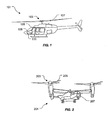
- Figures 1 and 2 show two different rotary aircraft utilizing the rotor hub assembly of the present application.
- Figure 1 shows a side view of a helicopter 101
- Figure 2 shows an oblique view of a tiltrotor aircraft 201.
- the rotor hub assembly is preferably used with rotary aircraft; however, it will be appreciated that the features disclosed herein are easily adapted for use with other types of vehicles and/or machinery.
- Helicopter 101 comprises a rotor hub assembly 103 carried by a fuselage 105.
- One or more rotor blades 107 operably associated with rotor hub assembly 103 provide flight for helicopter 101 and are controlled with a plurality of controllers within fuselage 105.
- a pilot can manipulate the cyclic controller 109 for changing the pitch angle of rotor blades 107 and/or manipulate pedals 111, thus providing vertical, horizontal, and yaw flight movement.
- Tiltrotor aircraft 201 includes two or more rotor hub assemblies 203 carried by rotatable nacelles.
- the rotatable nacelles provide means for allowing aircraft 201 to takeoff and land like a conventional helicopter and for horizontal flight like a conventional fixed wing aircraft. It should be understood that, like helicopter 101, tiltrotor aircraft 201 is provided with controls, e.g., cyclic controllers and pedals, for controlling movement of the aircraft.
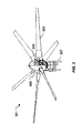
- FIG. 3 depicts an oblique view of the rotor hub assembly according to the preferred embodiment of the present application.
- Rotor hub assembly 301 efficiently controls movement created by the rotor blades, for example, lead/lag, centrifugal forces, feathering, and flapping.
- the both rotor hub assemblies 103 and 203 discussed above include the features of rotor hub assembly 301.
- the features of rotor hub assembly 301 disclosed herein are incorporated in assemblies for helicopters, tilt rotor aircraft, and other types of rotary aircraft, and including vehicles, and/or other types of machinery.
- Rotor hub assembly 301 comprises at least two rotor blades 303 operably associated with a swashplate 305.
- an aircraft engine (not shown) drives rotor blades 303, while swashplate 305 controls movement of rotor blades 303.
- rotor hub assembly 301 includes six rotor blades 303, which rotate along axis A1; however, it will be appreciated that the rotor hub assembly could include more or less rotor blades, depending on the preferred application.
- Rotor hub assembly 301 also includes one or more control links 307 operably associated with swashplate 305 for controlling movement of rotor blades 303.
- a housing 309 e.g., a spinner, is utilized to protect swashplate 305 and other components of rotor hub assembly 301.
- assembly 301 is an articulated rotor hub assembly, which allows the rotor blades to move independently; however, it will be appreciated that the features of assembly 301 could easily be incorporated in other types of hub assemblies, including non-articulated assemblies.
- rotor hub assembly 301 For ease of description, not all of the required subsystems and devices operably associated with rotor hub assembly 301 are shown. For example, the necessary sensors, connectors, power sources, mounting supports, circuitry, software, control systems, and so forth are not all shown in order to clearly depict the novel features of the rotor hub assembly. However, it should be understood that the rotor assembly disclosed herein is operably associated with these and other required systems and devices for operation, as conventionally known in the art, although not discussed and depicted in the drawings.
- Figure 5 is an enlarged view of Figure 4 taken at V-V and illustrated with some of the components of rotor hub assembly 301 removed for clarity.
- Swashplate 305 preferably comprises an upper driver plate 311 and a lower driver plate 313, both driver plates being utilized to rotate blades 303.
- An attachment device 315 is selectively placed between the two driver plates and is configured to pivotally and rotatably couple rotor blades 303 to swashplate 305.
- attachment device 315 is a trunnion formed in a T-shaped configuration.
- Attachment device 315 provides both rotational and pivoting means for rotor blades 303 to slightly rotate in a direction relative to axis A2 due to lead/lag forces created by the rotor blades during flight and to slightly pivot in a direction relative to axis A3 due to flapping of the rotor blades during flight.
- swashplate 305 includes a first port (not shown) extending through the thickness of the upper plate and a second port (not shown) extending through the thickness of the lower plate. Both ports are configured to receive distal ends of the attachment device.
- the ports are preferably circular in shape, thus allowing rotational movement of the attachment device along axis A2 in direction D1, as indicated with an arrow.
- the preferred embodiment utilizes a swashplate having two driver plates and circular ports to allow rotational movement of the attachment device.
- a swashplate having two driver plates and circular ports to allow rotational movement of the attachment device.
- alternative means for rotating the trunnion relative to the swashplate could be utilized in lieu of the preferred embodiment.
- the swashplate could include a single driver plate operably associated with a rotatable hinge assembly for coupling the rotor blades to the swashplate.
- the preferred embodiment provides significant advantageous, including added support and rigidity.
- Rotor hub assembly 301 further comprises a centrifugal bearing 317 (hereinafter referred to as a "C.F. bearing") carried by a rotor yoke arm 319 and one or more dual spring-rate dampers operably associated with attachment device 315.
- the C.F. bearing is configured to control centrifugal load created by the rotor blades
- the dual spring-rate damper is configured to selectively control lead-lag movement created by the rotor blades during flight.
- rotor hub assembly 301 includes two dual spring-rate dampers: a first damper 321 securely fastened to upper plate 311 via an upper arm 322 and a second damper 323 securely fastened to lower plate 313 via a lower arm 324.
- the dual spring-rate dampers selectively transition between a first spring rate and a second spring rate during flight.
- the dampers are configured to provide both rigid and soft damping ratios. This feature is particularly desired for use with tiltrotor aircraft because the damper switches from a locked configuration, thus creating a stiff hub assembly during airplane mode, to an unlocked configuration, which creates a softer hub assembly during helicopter mode.
- the stiff-in-plane configuration is generally required in airplane mode for stability above approxmatly 160 knots and in helicopter mode to avoid ground resonance issues due to wing and pylon frequencies.
- the flapping motion is minimized in airplane mode by using a full authority flap controller (not shown) that actively tilts the swashplate to limit the flapping to no more than 8 degrees.
- the flapping needs to be minimized to minimize rotor loads that are proportional to flapping in the stiff configuration.
- the soft-in-plane configuration is needed in helicopter mode to lower the hub loads which occur during high flapping for maneuvering in helicopter mode. Loads in articulated mode at limit flapping are much lower than in the rigid mode. Peak flapping is usually at high speed helicopter operation.
- FIG. 6 shows an oblique view of attachment device 315.
- attachment device 315 is manufactured in a T-shaped configuration having a longitudinal body 601 extending relatively normal to two lateral arms 603 and 605.
- Body 601 includes two opposing ending configured to rotatably couple to the swashplate: a first ending 607 configured to couple with the port extending through upper plate 311 and a second distal ending 609 configured to couple with the port extending through lower plate 313.
- the first and second endings provide rotational means for attachment device 315 to rotate relative to swashplate 305.
- the first and second distal endings are preferably circular shaft members configured to extend through and couple to the ports of the upper and lower driver plates. It should be appreciated that elastomeric material could be placed between the endings and the ports to provide slight elastic rotational movement of the attachment device 315 relative to the driver plates.
- Attachment device 315 comprises a bearing system 611 having at least three bearings: a first bearing 613 carried by lateral arm 603, a second bearing 615 carried by lateral arm 605, and a third bearing 617 disposed within body 601.
- Bearing system 611 accomidates flapping, feathering and lead-lag motions while reacting C.F. forces and hub shear forces.
- the bearing system provides a rigid attachment to the rotor mast (not shown) for all flight modes while allowing flapping and feathering motion.
- bearings 613 and 615 are journal bearings
- bearing 617 is a spherical bearing. All three bearings are coaxially aligned along axis A3 and configured to receive a shaft 619.
- Shaft 619 provides rotational means for allowing pivoting movement of yoke arm 319 relative to attachment device 315.
- yoke arm 319 pivotally couples to attachment device 315 via shaft 619, thus enabling flapping motion of the rotor blades relative to the hub assembly.
- damper 321 a cross-sectional top inner view of damper 321 is shown.
- damper 321 a detailed disclosure of one of the two dampers, damper 321, is shown and described below.
- damper 323 includes all of the features of damper 321.
- the two dual spring-rate dampers are configured to selectively switch between a first spring rate and a second spring rate during flight.
- the first spring rate is created via a plurality of elastomeric members selectively positioned within the damper, which create a desired shear resistance as a rotational force is exerted thereto. It will be appreciated that the elastomeric properties of the elastomeric materials can be selectively tailored to create a desired shear resistance, depending on the preferred application.
- the second spring rate is created with the plurality of elastomeric members in conjunction with fluid passing between two fluid reservoirs disposed within the damper. Further illustration and description of these features are provided below.
- Damper 321 comprises a non-rotational outer housing 701 rigidly attached to the upper driver plate via arm 322. Outer housing 701 receives the elastomeric members and one or more fluid chambers for creating the dual spring rates.
- damper 321 includes four fluid chambers for creating a desired damping effect; however, alternative embodiments could include more of less fluid chambers, depending on the preferred application.
- the fluid used in the preferred embodiment is an incompressible fluid, for example, hydraulic fluid, oil, and/or an alternative suitable fluid.
- Damper 321 further includes an inner housing 703 rotatably coupled to outer housing 701 via a plurality of elastomeric seals 705 and 706. Ending 607 of attachment device 315 couples to inner housing 703 via an elastomeric seal 707 disposed therebetween.
- the elastomeric seals create a first spring rate as attachment device 315 exerts a rotational movement relative to damper 321.
- four fluidly sealed chambers 709 are created between the two housings.
- the chambers are configured to create a second spring rate, as is further discussed in detail below.
- one of the four chambers is discussed in detail; however, it should be understood that all four chambers are similar in form and function.
- Chamber 709 comprises at least two reservoirs: a first reservoir 711 and a second adjacent reservoir 713, both reservoirs being in fluid communication with each other via a conduit 715.
- a vane 717 elastically attached to housing 701 separates the two fluid reservoirs. It should be appreciated that conduit 715 could pass through vane 717 in alternative embodiments.
- vane 717 moves within the reservoirs, thus causing fluid exchange therebetween.
- a valve 719 restricts fluid access through conduit 715.
- the damping effect is created solely from the elastomeric seals disposed within the damper.
- the fluid passes through the two reservoirs and the vane is allowed movement within the reservoirs.
- This scenario creates a second spring rate, a softer damping, as fluid is exchanged between the reservoirs.
- valve 719 is configured to completely open and close access through conduit 715; however, it will be appreciated that alternative embodiments could include a valve that allows selective flow rates through conduit 715.
- a ball valve or a sliding valve could be utilized in lieu of a valve that completely transitions between an opened and closed position.
- valve 719 Controlling the opening and closing of valve 719 is achieved with one or more manual controls carried in the fuselage and/or autonomously controlled by the aircraft control system. For example, in flight conditions when a softer damping effect is desired, valve 719 allows fluid to pass through conduit 715 merely by manipulating a control switch (not shown), and likewise, when a stiffer damping effect is desired, valve 719 can restrict fluid passing through conduit 715 by manipulating the same switch, which can either be manually or autonomously controlled.
- the opening and closing of valve 719 can be accomplished by hydraulic, electrical, or mechanical means.
- elastomeric seals 705 are preferably manufactured as "sandwich" structures, with alternating layers of an elastomeric material and a rigid, non-elastomeric material, such as a metal. This type of structure is nearly incompressible in a direction generally normal to the layers, while allowing for a predetermined amount of shearing motion.
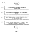
- Box 803 depicts attaching an attachment device to a swashplate.
- the attachment device provides pivot and rotational movement of a rotor blade attached thereto, as depicted in box 805.
- a dual spring rate damper is coupled to the attachment device, as depicted in box 807.
- box 809 depicts transitioning between the first spring rate and the second spring rate during flight.
Landscapes
- Engineering & Computer Science (AREA)
- Aviation & Aerospace Engineering (AREA)
- Mechanical Engineering (AREA)
- Tires In General (AREA)
- Fluid-Damping Devices (AREA)
- Vibration Dampers (AREA)
- Mixers Of The Rotary Stirring Type (AREA)
- Toys (AREA)
Claims (15)
- Ein dualer federkonstanter Dämpfer (321), der funktionsbereit mit einem Rotorblatt (303) verbunden ist, der Dämpfer (321) bestehend aus:einem Innengehäuse (703), das innerhalb eines drehungsfreien Außengehäuses (701) liegt;eine Reihe von elastomeren Teilen (705, 706), die das Innengehäuse (703) mit dem Außengehäuse (701) verbinden;und eine Flüssigkeitskammer (709), die zwischen dem Innengehäuse (703) und dem Außengehäuse (701) liegt;wobei die elastomeren Teile (705, 706) und die Flüssigkeitskammer (709) so gestaltet sind, dass sie die Lead/Lag-Bewegung des Rotorblattes (303) abfangen; charakterisiert dadurch, dassdas Innengehäuse (703) innerhalb des drehungsfreien Außengehäuses (701) rotieren kann; und dassdie Reihe der elastomeren Teile (705, 706) so konfiguriert sind, dass sie die Drehbewegung des Innengehäuses (703) im Verhältnis zum Außengehäuse (701) dämpfen.
- Der Dämpfer (321) in Anspruch 1, die Flüssigkeitskammer (709) bestehend aus: einem
ersten Flüssigkeitsbehälter (711);
einem zweiten Flüssigkeitsbehälter (713); und
einem Leitungsrohr (715) zum Flüssigkeitsaustausch mit dem ersten Flüssigkeitsbehälter (711) und dem zweiten Flüssigkeitsbehälter (713). - Der Dämpfer (321) in Anspruch 2 besteht darüberhinaus aus:einem Ventil (719) zum Flüssigkeitsaustausch über das Leitungsrohr (715), das Ventil (719) ist so gestaltet, dass es den Flüssigkeitsdurchlauf durch das Leitungsrohr (715) beschränkt.
- Der Dämpfer (321) in Anspruch 2 oder in Anspruch 3, wobei durch den elastischen Widerstand eine erste Federkonstante aus der Reihe der elastomeren Teile erstellt wird, da der Durchfluss der Flüssigkeit durch das Leitungsrohr (715) beschränkt ist; und
wobei durch den elastischen Widerstand eine zweite Federkonstante aus der Reihe der elastomeren Teile und den Flüssigkeitsdurchlauf zwischen dem ersten Flüssigkeitsbehälter (711) und dem zweiten Behälter (713) erstellt wird. - Der Dämpfer (321) jedes vorhergehenden Anspruchs, wobei jedes der Reihe der elastomeren Teile aus folgendem besteht:aus einer Reihe von Schichten elastischen Materials; undeiner Reihe von Schichten biegesteifen Materials, wobei die Reihe des biegesteifen Materials zwischen das elastische Material eingelegt ist.
- Der Dämpfer (321) jedes vorhergehenden Anspruchs, wobei der duale federkonstante Dämpfer funktionsbereit mit einer Aufnahmevorrichtung verbunden ist, um während des Fluges selektiv zwischen zwei oder mehr Federkonstanten wechseln zu können.
- Der Dämpfer (321) in Anspruch 6, wobei der duale federkonstante Dämpfer, der funktionsbereit mit der Aufnahmevorrichtung verbunden ist, die Kontrolle der Zentrifugalkräfte, der Schlagbewegung, Anstellwinkelverstellung und Lead-Lag-Bewegungen, die vom Rotorblatt (303) während des Fluges hervorgerufen werden, ermöglicht.
- Der Dämpfer (321) jedes vorhergehenden Anspruchs, wobei der duale federkonstante Dämpfer Teil einer Rotornaben-Einheit (301) ist.
- Der Dämpfer (321) in Anspruch 8, wobei der duale federkonstante Dämpfer sicher an der oberen Platte (311) der Rotornaben-Einheit (301) befestigt ist, während ein weiterer dualer federkonstanter Dämpfer sicher an der unteren Platte (313) der Rotornaben-Einheit (301) angebracht ist.
- Der Dämpfer (321) in Anspruch 9, wobei der duale federkonstante Dämpfer so gestaltet ist, dass er sowohl starre als auch elastische Dämpfungsverhältnisse liefert.
- Der Dämpfer (321) in Anspruch 2 oder jedem anderen Anspruch, der direkt oder indirekt von Anspruch 2 abhängt, wobei die zweite Federkonstante durch die Kontrolle des Flüssigkeitsaustausches zwischen dem ersten und zweiten Behälter (711, 713) ermittelt wird.
- Der Dämpfer (321) in Anspruch 11, wobei ein elastischerer Dämpfungseffekt erreicht wird, wenn ein Ventil (719) den Flüssigkeitsaustausch zwischen den Behältern (711, 713) ermöglicht, und ein starrerer Dämpfungseffekt erreicht wird, wenn ein Ventil (719) den Flüssigkeitsaustausch zwischen den Behältern (711, 713) beschränkt.
- Ein Fluggerät (101, 201) mit Dämpfer (321) gemäß aller Ansprüche 1 bis 12.
- Das Fluggerät (201) in Anspruch 13, wobei das Fluggerät ein Kipprotor-Fluggerät ist und der Dämpfer (321) so angeordnet ist, dass er im Flugzeug-Modus von einer starreren Nabeneinheit zu einer elastischeren Nabeneinheit im Helikopter-Modus wechseln kann.
- Das Fluggerät (201) in Anspruch 13, wobei der Dämpfer (321) dazu dient, zwischen starreren und elastischeren Konfigurationen hin- und herzuwechseln und das Fluggerät ein Kipprotor-Fluggerät ist, mit der Fähigkeit im Helikopter-Modus und im Flugzeug-Modus zu fliegen, und der Dämpfer(321) so gesteuert wird, dass er in einer starreren Konfiguration ist, wenn sich das Fluggerät (201) im Flugzeug-Modus befindet und mit über 160 Knoten fliegt, und der Dämpfer (321) so gesteuert wird, dass er in der elastischeren Konfiguration ist, wenn sich das Fluggerät (201) im Helikopter-Modus befindet und das Fluggerät (201) nahe am Boden ist und aufgrund der Flügel- und Pylon-Frequenz Bodenresonanzprobleme auftreten.
Applications Claiming Priority (2)
| Application Number | Priority Date | Filing Date | Title |
|---|---|---|---|
| US13/298,033 US9126680B2 (en) | 2011-11-16 | 2011-11-16 | Dual mode rotor hub assembly |
| EP11195396.4A EP2594482B1 (de) | 2011-11-16 | 2011-12-22 | Rotornabenanordnung mit Zweifachmodus |
Related Parent Applications (3)
| Application Number | Title | Priority Date | Filing Date |
|---|---|---|---|
| EP11195396.4 Division | 2011-12-22 | ||
| EP11195396.4A Division-Into EP2594482B1 (de) | 2011-11-16 | 2011-12-22 | Rotornabenanordnung mit Zweifachmodus |
| EP11195396.4A Division EP2594482B1 (de) | 2011-11-16 | 2011-12-22 | Rotornabenanordnung mit Zweifachmodus |
Publications (2)
| Publication Number | Publication Date |
|---|---|
| EP2594483A1 EP2594483A1 (de) | 2013-05-22 |
| EP2594483B1 true EP2594483B1 (de) | 2014-09-24 |
Family
ID=45400986
Family Applications (2)
| Application Number | Title | Priority Date | Filing Date |
|---|---|---|---|
| EP12175816.3A Active EP2594483B1 (de) | 2011-11-16 | 2011-12-22 | Rotornabenanordnung mit Zweifachmodus |
| EP11195396.4A Active EP2594482B1 (de) | 2011-11-16 | 2011-12-22 | Rotornabenanordnung mit Zweifachmodus |
Family Applications After (1)
| Application Number | Title | Priority Date | Filing Date |
|---|---|---|---|
| EP11195396.4A Active EP2594482B1 (de) | 2011-11-16 | 2011-12-22 | Rotornabenanordnung mit Zweifachmodus |
Country Status (4)
| Country | Link |
|---|---|
| US (1) | US9126680B2 (de) |
| EP (2) | EP2594483B1 (de) |
| CN (1) | CN103112584B (de) |
| CA (1) | CA2794039C (de) |
Families Citing this family (15)
| Publication number | Priority date | Publication date | Assignee | Title |
|---|---|---|---|---|
| US9352830B2 (en) * | 2012-04-25 | 2016-05-31 | Textron Innovations Inc. | Aircraft rotor with discrete flap hinge |
| US9656744B2 (en) * | 2014-05-21 | 2017-05-23 | Bell Helicopter Textron Inc. | Adjustable blade-to-hub lead-lag damper attachment |
| EP3388546A4 (de) * | 2015-12-02 | 2019-07-31 | Mitsubishi Hitachi Tool Engineering, Ltd. | Hartbeschichtung, mit hartbeschichtung beschichtetes element und herstellungsverfahren dafür sowie ziel zur herstellung der hartbeschichtung und herstellungsverfahren dafür |
| US10569870B2 (en) | 2016-11-18 | 2020-02-25 | Textron Innovations Inc. | Proprotor systems for tiltrotor aircraft |
| US10232932B2 (en) | 2017-03-22 | 2019-03-19 | Bell Helicopter Textron Inc. | High stiffness hub assembly for proprotor systems |
| US10457380B2 (en) * | 2017-06-28 | 2019-10-29 | Bell Textron Inc. | Articulated rotor systems with pitch independent damping |
| US10507912B2 (en) | 2017-07-13 | 2019-12-17 | Bell Textron Inc. | Inboard bearing assemblies with improved accessibility |
| US10494091B2 (en) | 2017-07-13 | 2019-12-03 | Bell Textron Inc. | Hub bolt supported inboard bearing assemblies |
| US10514060B2 (en) | 2017-07-13 | 2019-12-24 | Textron Innovations Inc. | Inboard bearing assemblies with anti-rotation features |
| US10472059B2 (en) | 2017-07-13 | 2019-11-12 | Bell Textron Inc. | Inboard bearing assemblies for proprotor systems |
| US10486807B2 (en) | 2017-07-13 | 2019-11-26 | Bell Textron Inc. | Inboard bearing assemblies having independent shoes |
| US10479497B2 (en) | 2017-07-13 | 2019-11-19 | Bell Textron Inc. | Inboard bearing assemblies having load transfer shoe bolts |
| US11027834B2 (en) | 2018-02-22 | 2021-06-08 | Textron Innovations Inc. | Inboard centrifugal force bearing attachment |
| US10597150B2 (en) | 2018-04-24 | 2020-03-24 | Textron Innovations Inc. | Articulated rotor systems with blade-to-blade damping |
| CN120942545A (zh) * | 2025-08-20 | 2025-11-14 | 四川沃飞长空科技发展有限公司 | 桨毂组件、螺旋桨、飞行器 |
Citations (2)
| Publication number | Priority date | Publication date | Assignee | Title |
|---|---|---|---|---|
| US4768630A (en) * | 1985-12-30 | 1988-09-06 | Aerospatiale Societe Nationale Industrielle | Rotary damper |
| US20110236209A1 (en) * | 2010-03-29 | 2011-09-29 | Eurocopter | Blade damper, and a rotor fitted with such a damper |
Family Cites Families (11)
| Publication number | Priority date | Publication date | Assignee | Title |
|---|---|---|---|---|
| US2774553A (en) | 1955-04-04 | 1956-12-18 | United Aircraft Corp | Damper by-pass for lag-lead control of helicopter rotor blades |
| US3134444A (en) * | 1961-08-23 | 1964-05-26 | Kaman Aircraft Corp | Aircraft rotor-propeller |
| US4543040A (en) * | 1982-09-30 | 1985-09-24 | The Boeing Company | Helicopter rotor system |
| US5501434A (en) * | 1994-05-10 | 1996-03-26 | Lord Corporation | Hybrid fluid and elastomer damper |
| US6889965B2 (en) * | 2001-10-10 | 2005-05-10 | The Boeing Company | Opposing conical preloaded elastomeric bearing assembly |
| US6758466B2 (en) * | 2002-11-06 | 2004-07-06 | Lord Corporation | Fluid-elastomeric damper assembly including internal pumping mechanism |
| FR2848524B1 (fr) * | 2002-12-13 | 2005-12-09 | Eurocopter France | Dispositif a plateaux cycliques de commande du pas des pales d'un rotor de giravion |
| CN102182787A (zh) | 2003-08-27 | 2011-09-14 | 贝尔直升机泰克斯特龙公司 | 双弹簧刚度阻尼器 |
| EA200900036A1 (ru) * | 2006-06-20 | 2009-06-30 | Белл Хеликоптер Текстрон Инк. | Центробежный подшипник с постоянным моментом тангажа |
| US8413772B2 (en) | 2008-02-12 | 2013-04-09 | Techno-Sciences, Inc. | Magnetorheological fluid elastic lag damper for helicopter rotors |
| FR2954274B1 (fr) * | 2009-12-17 | 2012-02-24 | Eurocopter France | Mecanisme amortisseur de vibrations, et appareil volant muni d'une structure porteuse et d'un rotor muni d'un tel mecanisme |
-
2011
- 2011-11-16 US US13/298,033 patent/US9126680B2/en active Active
- 2011-12-22 EP EP12175816.3A patent/EP2594483B1/de active Active
- 2011-12-22 EP EP11195396.4A patent/EP2594482B1/de active Active
-
2012
- 2012-10-24 CN CN201210409284.0A patent/CN103112584B/zh not_active Expired - Fee Related
- 2012-11-01 CA CA2794039A patent/CA2794039C/en active Active
Patent Citations (2)
| Publication number | Priority date | Publication date | Assignee | Title |
|---|---|---|---|---|
| US4768630A (en) * | 1985-12-30 | 1988-09-06 | Aerospatiale Societe Nationale Industrielle | Rotary damper |
| US20110236209A1 (en) * | 2010-03-29 | 2011-09-29 | Eurocopter | Blade damper, and a rotor fitted with such a damper |
Also Published As
| Publication number | Publication date |
|---|---|
| CA2794039A1 (en) | 2013-05-16 |
| EP2594482B1 (de) | 2015-03-18 |
| CN103112584B (zh) | 2016-09-14 |
| CN103112584A (zh) | 2013-05-22 |
| US20130121827A1 (en) | 2013-05-16 |
| CA2794039C (en) | 2016-01-19 |
| EP2594483A1 (de) | 2013-05-22 |
| US9126680B2 (en) | 2015-09-08 |
| EP2594482A1 (de) | 2013-05-22 |
Similar Documents
| Publication | Publication Date | Title |
|---|---|---|
| EP2594483B1 (de) | Rotornabenanordnung mit Zweifachmodus | |
| US8181755B2 (en) | Dual spring rate damper | |
| EP2686239B1 (de) | Rotornabe für schaufeln mit hohem trägheitsmoment | |
| EP2778062B1 (de) | Kardanisch gelagerte Heckrotornabe mit Elastomer-Zentrifugalkraftlager für Rotorblatthaltung und Anstellwinkeländerung | |
| US10625846B2 (en) | Adaptable rotor control system for a variable number of blades | |
| WO2016210265A1 (en) | Adaptive landing gear assembly for rotary wing aircraft | |
| US10259576B2 (en) | Articulated main rotor hub with inwardly CF bearing and 3% flapping hinge offset | |
| CA2854317C (en) | Rotor system of a rotary wing aircraft | |
| US10745120B2 (en) | Adaptable rotor control system for a variable number of blades | |
| EP4558399B1 (de) | Redundanter lastweg für einen angetriebenen hubkippaktuator | |
| EP2778058B1 (de) | Mehrgliedriges Gleichlaufgelenk | |
| US6082968A (en) | Centrifugally activated variable damper assembly |
Legal Events
| Date | Code | Title | Description |
|---|---|---|---|
| PUAI | Public reference made under article 153(3) epc to a published international application that has entered the european phase |
Free format text: ORIGINAL CODE: 0009012 |
|
| 17P | Request for examination filed |
Effective date: 20120710 |
|
| AC | Divisional application: reference to earlier application |
Ref document number: 2594482 Country of ref document: EP Kind code of ref document: P |
|
| AK | Designated contracting states |
Kind code of ref document: A1 Designated state(s): AL AT BE BG CH CY CZ DE DK EE ES FI FR GB GR HR HU IE IS IT LI LT LU LV MC MK MT NL NO PL PT RO RS SE SI SK SM TR |
|
| AX | Request for extension of the european patent |
Extension state: BA ME |
|
| 17Q | First examination report despatched |
Effective date: 20131127 |
|
| GRAP | Despatch of communication of intention to grant a patent |
Free format text: ORIGINAL CODE: EPIDOSNIGR1 |
|
| GRAS | Grant fee paid |
Free format text: ORIGINAL CODE: EPIDOSNIGR3 |
|
| GRAA | (expected) grant |
Free format text: ORIGINAL CODE: 0009210 |
|
| INTG | Intention to grant announced |
Effective date: 20140731 |
|
| AC | Divisional application: reference to earlier application |
Ref document number: 2594482 Country of ref document: EP Kind code of ref document: P |
|
| AK | Designated contracting states |
Kind code of ref document: B1 Designated state(s): AL AT BE BG CH CY CZ DE DK EE ES FI FR GB GR HR HU IE IS IT LI LT LU LV MC MK MT NL NO PL PT RO RS SE SI SK SM TR |
|
| REG | Reference to a national code |
Ref country code: GB Ref legal event code: FG4D |
|
| REG | Reference to a national code |
Ref country code: CH Ref legal event code: EP |
|
| REG | Reference to a national code |
Ref country code: AT Ref legal event code: REF Ref document number: 688491 Country of ref document: AT Kind code of ref document: T Effective date: 20141015 |
|
| REG | Reference to a national code |
Ref country code: IE Ref legal event code: FG4D |
|
| REG | Reference to a national code |
Ref country code: DE Ref legal event code: R096 Ref document number: 602011010191 Country of ref document: DE Effective date: 20141106 |
|
| PG25 | Lapsed in a contracting state [announced via postgrant information from national office to epo] |
Ref country code: NO Free format text: LAPSE BECAUSE OF FAILURE TO SUBMIT A TRANSLATION OF THE DESCRIPTION OR TO PAY THE FEE WITHIN THE PRESCRIBED TIME-LIMIT Effective date: 20141224 Ref country code: SE Free format text: LAPSE BECAUSE OF FAILURE TO SUBMIT A TRANSLATION OF THE DESCRIPTION OR TO PAY THE FEE WITHIN THE PRESCRIBED TIME-LIMIT Effective date: 20140924 Ref country code: FI Free format text: LAPSE BECAUSE OF FAILURE TO SUBMIT A TRANSLATION OF THE DESCRIPTION OR TO PAY THE FEE WITHIN THE PRESCRIBED TIME-LIMIT Effective date: 20140924 Ref country code: LT Free format text: LAPSE BECAUSE OF FAILURE TO SUBMIT A TRANSLATION OF THE DESCRIPTION OR TO PAY THE FEE WITHIN THE PRESCRIBED TIME-LIMIT Effective date: 20140924 Ref country code: GR Free format text: LAPSE BECAUSE OF FAILURE TO SUBMIT A TRANSLATION OF THE DESCRIPTION OR TO PAY THE FEE WITHIN THE PRESCRIBED TIME-LIMIT Effective date: 20141225 |
|
| REG | Reference to a national code |
Ref country code: LT Ref legal event code: MG4D Ref country code: NL Ref legal event code: VDEP Effective date: 20140924 |
|
| PG25 | Lapsed in a contracting state [announced via postgrant information from national office to epo] |
Ref country code: LV Free format text: LAPSE BECAUSE OF FAILURE TO SUBMIT A TRANSLATION OF THE DESCRIPTION OR TO PAY THE FEE WITHIN THE PRESCRIBED TIME-LIMIT Effective date: 20140924 Ref country code: RS Free format text: LAPSE BECAUSE OF FAILURE TO SUBMIT A TRANSLATION OF THE DESCRIPTION OR TO PAY THE FEE WITHIN THE PRESCRIBED TIME-LIMIT Effective date: 20140924 Ref country code: CY Free format text: LAPSE BECAUSE OF FAILURE TO SUBMIT A TRANSLATION OF THE DESCRIPTION OR TO PAY THE FEE WITHIN THE PRESCRIBED TIME-LIMIT Effective date: 20140924 Ref country code: HR Free format text: LAPSE BECAUSE OF FAILURE TO SUBMIT A TRANSLATION OF THE DESCRIPTION OR TO PAY THE FEE WITHIN THE PRESCRIBED TIME-LIMIT Effective date: 20140924 |
|
| REG | Reference to a national code |
Ref country code: AT Ref legal event code: MK05 Ref document number: 688491 Country of ref document: AT Kind code of ref document: T Effective date: 20140924 |
|
| PG25 | Lapsed in a contracting state [announced via postgrant information from national office to epo] |
Ref country code: NL Free format text: LAPSE BECAUSE OF FAILURE TO SUBMIT A TRANSLATION OF THE DESCRIPTION OR TO PAY THE FEE WITHIN THE PRESCRIBED TIME-LIMIT Effective date: 20140924 |
|
| PG25 | Lapsed in a contracting state [announced via postgrant information from national office to epo] |
Ref country code: IS Free format text: LAPSE BECAUSE OF FAILURE TO SUBMIT A TRANSLATION OF THE DESCRIPTION OR TO PAY THE FEE WITHIN THE PRESCRIBED TIME-LIMIT Effective date: 20150124 Ref country code: PT Free format text: LAPSE BECAUSE OF FAILURE TO SUBMIT A TRANSLATION OF THE DESCRIPTION OR TO PAY THE FEE WITHIN THE PRESCRIBED TIME-LIMIT Effective date: 20150126 Ref country code: EE Free format text: LAPSE BECAUSE OF FAILURE TO SUBMIT A TRANSLATION OF THE DESCRIPTION OR TO PAY THE FEE WITHIN THE PRESCRIBED TIME-LIMIT Effective date: 20140924 Ref country code: ES Free format text: LAPSE BECAUSE OF FAILURE TO SUBMIT A TRANSLATION OF THE DESCRIPTION OR TO PAY THE FEE WITHIN THE PRESCRIBED TIME-LIMIT Effective date: 20140924 Ref country code: RO Free format text: LAPSE BECAUSE OF FAILURE TO SUBMIT A TRANSLATION OF THE DESCRIPTION OR TO PAY THE FEE WITHIN THE PRESCRIBED TIME-LIMIT Effective date: 20140924 Ref country code: CZ Free format text: LAPSE BECAUSE OF FAILURE TO SUBMIT A TRANSLATION OF THE DESCRIPTION OR TO PAY THE FEE WITHIN THE PRESCRIBED TIME-LIMIT Effective date: 20140924 Ref country code: SK Free format text: LAPSE BECAUSE OF FAILURE TO SUBMIT A TRANSLATION OF THE DESCRIPTION OR TO PAY THE FEE WITHIN THE PRESCRIBED TIME-LIMIT Effective date: 20140924 |
|
| PG25 | Lapsed in a contracting state [announced via postgrant information from national office to epo] |
Ref country code: AT Free format text: LAPSE BECAUSE OF FAILURE TO SUBMIT A TRANSLATION OF THE DESCRIPTION OR TO PAY THE FEE WITHIN THE PRESCRIBED TIME-LIMIT Effective date: 20140924 Ref country code: PL Free format text: LAPSE BECAUSE OF FAILURE TO SUBMIT A TRANSLATION OF THE DESCRIPTION OR TO PAY THE FEE WITHIN THE PRESCRIBED TIME-LIMIT Effective date: 20140924 |
|
| REG | Reference to a national code |
Ref country code: DE Ref legal event code: R097 Ref document number: 602011010191 Country of ref document: DE |
|
| PG25 | Lapsed in a contracting state [announced via postgrant information from national office to epo] |
Ref country code: BE Free format text: LAPSE BECAUSE OF NON-PAYMENT OF DUE FEES Effective date: 20141231 |
|
| PG25 | Lapsed in a contracting state [announced via postgrant information from national office to epo] |
Ref country code: DK Free format text: LAPSE BECAUSE OF FAILURE TO SUBMIT A TRANSLATION OF THE DESCRIPTION OR TO PAY THE FEE WITHIN THE PRESCRIBED TIME-LIMIT Effective date: 20140924 Ref country code: LU Free format text: LAPSE BECAUSE OF FAILURE TO SUBMIT A TRANSLATION OF THE DESCRIPTION OR TO PAY THE FEE WITHIN THE PRESCRIBED TIME-LIMIT Effective date: 20141222 |
|
| PLBE | No opposition filed within time limit |
Free format text: ORIGINAL CODE: 0009261 |
|
| REG | Reference to a national code |
Ref country code: CH Ref legal event code: PL |
|
| STAA | Information on the status of an ep patent application or granted ep patent |
Free format text: STATUS: NO OPPOSITION FILED WITHIN TIME LIMIT |
|
| 26N | No opposition filed |
Effective date: 20150625 |
|
| REG | Reference to a national code |
Ref country code: IE Ref legal event code: MM4A |
|
| PG25 | Lapsed in a contracting state [announced via postgrant information from national office to epo] |
Ref country code: IE Free format text: LAPSE BECAUSE OF NON-PAYMENT OF DUE FEES Effective date: 20141222 Ref country code: LI Free format text: LAPSE BECAUSE OF NON-PAYMENT OF DUE FEES Effective date: 20141231 Ref country code: CH Free format text: LAPSE BECAUSE OF NON-PAYMENT OF DUE FEES Effective date: 20141231 |
|
| REG | Reference to a national code |
Ref country code: FR Ref legal event code: PLFP Year of fee payment: 5 |
|
| PG25 | Lapsed in a contracting state [announced via postgrant information from national office to epo] |
Ref country code: SI Free format text: LAPSE BECAUSE OF FAILURE TO SUBMIT A TRANSLATION OF THE DESCRIPTION OR TO PAY THE FEE WITHIN THE PRESCRIBED TIME-LIMIT Effective date: 20140924 |
|
| PG25 | Lapsed in a contracting state [announced via postgrant information from national office to epo] |
Ref country code: SM Free format text: LAPSE BECAUSE OF FAILURE TO SUBMIT A TRANSLATION OF THE DESCRIPTION OR TO PAY THE FEE WITHIN THE PRESCRIBED TIME-LIMIT Effective date: 20140924 |
|
| PG25 | Lapsed in a contracting state [announced via postgrant information from national office to epo] |
Ref country code: MC Free format text: LAPSE BECAUSE OF FAILURE TO SUBMIT A TRANSLATION OF THE DESCRIPTION OR TO PAY THE FEE WITHIN THE PRESCRIBED TIME-LIMIT Effective date: 20140924 |
|
| PG25 | Lapsed in a contracting state [announced via postgrant information from national office to epo] |
Ref country code: BG Free format text: LAPSE BECAUSE OF FAILURE TO SUBMIT A TRANSLATION OF THE DESCRIPTION OR TO PAY THE FEE WITHIN THE PRESCRIBED TIME-LIMIT Effective date: 20140924 |
|
| PG25 | Lapsed in a contracting state [announced via postgrant information from national office to epo] |
Ref country code: HU Free format text: LAPSE BECAUSE OF FAILURE TO SUBMIT A TRANSLATION OF THE DESCRIPTION OR TO PAY THE FEE WITHIN THE PRESCRIBED TIME-LIMIT; INVALID AB INITIO Effective date: 20111222 Ref country code: TR Free format text: LAPSE BECAUSE OF FAILURE TO SUBMIT A TRANSLATION OF THE DESCRIPTION OR TO PAY THE FEE WITHIN THE PRESCRIBED TIME-LIMIT Effective date: 20140924 Ref country code: MT Free format text: LAPSE BECAUSE OF FAILURE TO SUBMIT A TRANSLATION OF THE DESCRIPTION OR TO PAY THE FEE WITHIN THE PRESCRIBED TIME-LIMIT Effective date: 20140924 |
|
| REG | Reference to a national code |
Ref country code: FR Ref legal event code: PLFP Year of fee payment: 6 |
|
| PG25 | Lapsed in a contracting state [announced via postgrant information from national office to epo] |
Ref country code: IT Free format text: LAPSE BECAUSE OF NON-PAYMENT OF DUE FEES Effective date: 20151222 |
|
| PG25 | Lapsed in a contracting state [announced via postgrant information from national office to epo] |
Ref country code: IT Free format text: LAPSE BECAUSE OF NON-PAYMENT OF DUE FEES Effective date: 20151222 |
|
| PGRI | Patent reinstated in contracting state [announced from national office to epo] |
Ref country code: IT Effective date: 20170710 |
|
| REG | Reference to a national code |
Ref country code: FR Ref legal event code: PLFP Year of fee payment: 7 |
|
| PG25 | Lapsed in a contracting state [announced via postgrant information from national office to epo] |
Ref country code: MK Free format text: LAPSE BECAUSE OF FAILURE TO SUBMIT A TRANSLATION OF THE DESCRIPTION OR TO PAY THE FEE WITHIN THE PRESCRIBED TIME-LIMIT Effective date: 20140924 |
|
| PG25 | Lapsed in a contracting state [announced via postgrant information from national office to epo] |
Ref country code: AL Free format text: LAPSE BECAUSE OF FAILURE TO SUBMIT A TRANSLATION OF THE DESCRIPTION OR TO PAY THE FEE WITHIN THE PRESCRIBED TIME-LIMIT Effective date: 20140924 |
|
| P01 | Opt-out of the competence of the unified patent court (upc) registered |
Effective date: 20230602 |
|
| PGFP | Annual fee paid to national office [announced via postgrant information from national office to epo] |
Ref country code: GB Payment date: 20251229 Year of fee payment: 15 |
|
| PGFP | Annual fee paid to national office [announced via postgrant information from national office to epo] |
Ref country code: IT Payment date: 20251219 Year of fee payment: 15 |
|
| PGFP | Annual fee paid to national office [announced via postgrant information from national office to epo] |
Ref country code: FR Payment date: 20251226 Year of fee payment: 15 |
|
| PGFP | Annual fee paid to national office [announced via postgrant information from national office to epo] |
Ref country code: DE Payment date: 20251229 Year of fee payment: 15 |