EP2594499B1 - Inline-Abfüllanlagen für Behälter mit Flüssigkeiten und Abfüllverfahren - Google Patents
Inline-Abfüllanlagen für Behälter mit Flüssigkeiten und Abfüllverfahren Download PDFInfo
- Publication number
- EP2594499B1 EP2594499B1 EP20120192884 EP12192884A EP2594499B1 EP 2594499 B1 EP2594499 B1 EP 2594499B1 EP 20120192884 EP20120192884 EP 20120192884 EP 12192884 A EP12192884 A EP 12192884A EP 2594499 B1 EP2594499 B1 EP 2594499B1
- Authority
- EP
- European Patent Office
- Prior art keywords
- container
- containers
- capping
- machine
- measurement value
- Prior art date
- Legal status (The legal status is an assumption and is not a legal conclusion. Google has not performed a legal analysis and makes no representation as to the accuracy of the status listed.)
- Active
Links
Images




Classifications
-
- B—PERFORMING OPERATIONS; TRANSPORTING
- B65—CONVEYING; PACKING; STORING; HANDLING THIN OR FILAMENTARY MATERIAL
- B65C—LABELLING OR TAGGING MACHINES, APPARATUS, OR PROCESSES
- B65C9/00—Details of labelling machines or apparatus
- B65C9/46—Applying date marks, code marks, or the like, to the label during labelling
-
- B—PERFORMING OPERATIONS; TRANSPORTING
- B67—OPENING, CLOSING OR CLEANING BOTTLES, JARS OR SIMILAR CONTAINERS; LIQUID HANDLING
- B67B—APPLYING CLOSURE MEMBERS TO BOTTLES JARS, OR SIMILAR CONTAINERS; OPENING CLOSED CONTAINERS
- B67B3/00—Closing bottles, jars or similar containers by applying caps
- B67B3/26—Applications of control, warning, or safety devices in capping machinery
-
- B—PERFORMING OPERATIONS; TRANSPORTING
- B67—OPENING, CLOSING OR CLEANING BOTTLES, JARS OR SIMILAR CONTAINERS; LIQUID HANDLING
- B67C—CLEANING, FILLING WITH LIQUIDS OR SEMILIQUIDS, OR EMPTYING, OF BOTTLES, JARS, CANS, CASKS, BARRELS, OR SIMILAR CONTAINERS, NOT OTHERWISE PROVIDED FOR; FUNNELS
- B67C3/00—Bottling liquids or semiliquids; Filling jars or cans with liquids or semiliquids using bottling or like apparatus; Filling casks or barrels with liquids or semiliquids
- B67C3/007—Applications of control, warning or safety devices in filling machinery
-
- B—PERFORMING OPERATIONS; TRANSPORTING
- B67—OPENING, CLOSING OR CLEANING BOTTLES, JARS OR SIMILAR CONTAINERS; LIQUID HANDLING
- B67C—CLEANING, FILLING WITH LIQUIDS OR SEMILIQUIDS, OR EMPTYING, OF BOTTLES, JARS, CANS, CASKS, BARRELS, OR SIMILAR CONTAINERS, NOT OTHERWISE PROVIDED FOR; FUNNELS
- B67C7/00—Concurrent cleaning, filling, and closing of bottles; Processes or devices for at least two of these operations
- B67C7/0073—Sterilising, aseptic filling and closing
Definitions
- the present invention regards an in-line bottling plant for containers with liquids and a bottling process, in particular by means of said plant, according to the preamble of the respective independent claims 1 and 12 and as known from EP 2 295 226 A1 .
- the present plant and the process are advantageously intended to be employed in the beverage industry in industrial bottling lines where it is necessary to automatically carry out the filling and the capping of a considerable number of bottles per hour.
- the plant and the process, object of the present invention are preferably employable for packaging alimentary drinks, in particular of considerable added value, in which it is important to optimize the productive process or to control afterward, even after a period of time, the conditions under which the packaging process was carried out.
- the present invention is therefore falls within the technical field of attaining industrial plants for bottling drinks such as wine, spirits, mineral waters, fruit juices, alimentary drinks or other liquids.
- the industrial bottling plants conventionally available on the market provide to move the bottles to be bottled (by means of, for example, hollow wheels, augers or conveyor belts) through multiple operating machines arranged in series, usually comprising at least one rinsing machine, a filling machine and a capping machine.
- the latter can be of the type provided with capping heads with slidable blocks, in order to insert and compress cork caps inside the neck of the bottles, or of capper type for mounting capsules on the neck of the bottles through a screwing or forming operation of the capsule on the external thread of the bottle neck.
- the single machines of the production chain can be provided with dedicated mechanisms and diagnostic means adapted to prevent the bottle from being subjected to the treatment provided by the machine, if the operating conditions thereof are not met.
- the isobaric filling machines for filling bottles with carbonated liquids provide for the possibility to prevent the opening of the relative valve group, if the desired filling pressure in the bottle is not reached.
- bottles leaving a machine can be stowed in storage spaces before being transported to the next machine for the further operation of the packaging process.
- the monitoring of the production process intended as control of the supplier merchandise and finished product (packaged bottles) as well as the distribution process has the limit of identifying only uniform batches with reference to the conformity requirements, and does not allow identifying the single bottles and hence evaluating the conditions of the rinsing process to which they were subjected.
- the bottling processes and plants up to now do not allow evaluating, in a differentiated manner, the single bottles in accordance to how they were handled in the productive process in relation to the different machines and steps of rinsing, filling, capping and labeling.
- An important limit of the current bottling processes lies in allowing the recognition and traceability of the productive process only with reference to what occurs upstream and downstream of the abovementioned bottling steps.
- Production processes are known that provide for the use of rotary labeling machines, capable of indicating the origin of the viticulture production on the final bottled product, through the indication (for example) of a number relative to the pertinent consortium. This allows relating the wine bottle, wherever this was sold, to the territory where the grapes were produced and the wine made, but it does not allow the producer, in case of product defect, to trace back to the cause of such defect.
- the response of the final user represents important feedback for the optimization of the bottling process. Yet the bottling processes present on the market today do not consider such feedback.
- a defect in the capping of a bottle may be due to problems related to the bottle, the cap or the capping steps.
- the computer control and supervision of the current systems regarding the bottling process are mainly aimed at automatically managing the launching of the orders in production, for such purpose setting the machines as a function of the bottle format, the wine, the caps, as well as, for example, the exact number of bottles to be provided for the execution of that specific order; the computer control and supervision are also aimed at managing the labeling, by sending the product batch reference information to the inkjet printers for printing the labels of the bottles and the boxes.
- the problem underlying the present invention is therefore that of overcoming the drawbacks manifested by the plants and by the capping processes of known type, by providing a plant and a process that allow controlling the steps of the packaging process on the single bottle.
- Another object of the present invention is to obtain a plant and a process that allow minimizing raw material waste, preventing the production of finished products that do not meet at least one of the expected requirements.
- Another object of the present invention is to obtain a plant and a process that allow the traceability on the single bottle in all the bottling process steps.
- Another object of the present invention is to obtain a plant and a process that allow, over a period of time, to determine the cause of a defect in the finished product, and then to correct the productive process or plant.
- Another object of the present invention is to obtain a plant and a process that are inexpensive to achieve.
- a further object of the present invention is to obtain a plant that is structurally simple and entirely reliable from an operations standpoint.
- the plant is intended to be employed in the industrial bottling processes in order to package containers with liquids, in particular of alimentary type such as wine and water.
- Such plant consists, in a per se conventional manner, of at least one filling machine 3, at least one capping machine 4, and at least one labeling machine 5, preferably all with rotary turntable, i.e. each provided with a plurality of operative heads mounted peripherally on its own turntable, respectively for rinsing, filling, capping and labeling the containers moving through the plant 1.
- a rinsing machine 2 is also preferably provided.
- the plant 1 also comprises a capper machine 6 for covering the head of the bottle with a capsule made of aluminum or another deformable material.
- the plant 1 comprises transportation means 7 adapted to move the containers from an inlet section 8 of the plant 1 to an outlet section 9 of the plant 1, maintaining the same sequence over the entire travel, i.e. without the containers changing their order.
- the rotary rinsing machine 2 is arranged to intercept the transportation means 7 and it is provided with a plurality of operative rinsing groups 10 mounted peripherally on a first turntable and adapted to carry out a first rinsing operation separately on the single containers.
- Each rinsing group 10 comprises, in a manner per se known to the man skilled in the art and hence not discussed in detail below: - a gripper 11, hinged to the first turntable, and able to be actuated to grip a container to be rinsed, and to rotate by 180° in order to move it between an upright position and an inverted position; - an injection nozzle 12, which is mounted on the turntable aligned with the mouth of the container in inverted position, and it is connected by means of a feeding duct 13 to a distribution valve 14 of a washing fluid with which it rinses the container.
- the rinsing machine 2 is fed in particular by means of an auger 7' of the transportation means 7; such auger is arranged at the inlet section 8 of the plant 1.
- the auger 7' transfers the containers to an inlet starwheel 49 of the rinsing machine 2 and takes them again, once they have been rinsed, at an outlet starwheel 69 of the same rinsing machine 2.
- a rotary filling machine 3 Downstream of the inlet section 8 of the plant 1, and in particular downstream of the rinsing machine 2, to intercept the transportation means 7 there is a rotary filling machine 3; the latter is provided with a plurality of valve groups 15, adapted to carry out a second filling operation, with a liquid to be bottled, separately on the single containers.
- the filling machines are commonly classified as low vacuum machines, isobaric machines, low pressure machines, gravity machines, etc.
- the filling machine 3 of the plant, object of the present invention comprises, in a per se conventional manner: a second rotary turntable carrying a mounted tank 16 for containing a liquid to be bottled and a plurality of valve groups 15 mounted peripherally on said rotary turntable and each comprising a supply duct 18 hydraulically connected to the tank 16 for the flow of the liquid to the containers to be filled, an air return tube 19 and a shutter 20 movable between an open position and a closed position of the supply duct 18 in order to adjust the flow of said liquid in said containers.
- the auger transfers the containers to a further inlet starwheel 51 of the filling machine 3, taking them again once filled at an outlet starwheel 53 of the same filling machine 3.
- a rotary capping machine 4 is provided, which in turn is provided with a plurality of capping heads 21 adapted to carry out a third capping operation separately on the single containers.
- the capping machine 4 can be of the type provided with operative capping heads 21 with slidable blocks, in order to insert and compress cork caps inside the neck of the bottles, or of capping type in order to mount capsules on the neck of the containers through a screwing operation or a forming operation of the capsules on the external thread of the neck of the container.
- operative capping heads 21 for compressible caps are mounted peripherally on a third rotary turntable and each comprises clamping means 22 for compressing a cap 24 from a widened shape to a compressed shape susceptible to being inserted in the mouth of a bottle; thrusting means 23 mounted above the clamping means 22, able to be actuated to push the cap 24 retained in compressed form by the clamping means 22, along a vertical capping axis, inside the neck of the container.
- Each head 21 also arranges a conveying group 25 provided with a sealing surface intended to receive the mouth of the container in abutment and a centering device 26 mounted on the lower part of the clamping means 22, equipped with a passage hole aligned vertically with respect to the capping axis and to the mouth of the container and intended to convey the cap 24 thrust by the thrusting means 23 in the mouth of the container arranged resting on the sealing surface.
- the conveyor group 25 is provided with at least one air passage channel 27, which is susceptible to place in communication the internal volume of the bottle delimited by the cap 24 sealingly positioned in the passage hole, with means for suctioning and/or injecting inert gas.
- the caps consisting of screw capsules, generally of metallic or plastic material, are screwed on the threaded top of containers.
- each head of this type is usually provided with grippers for first gripping the capsules and then screwing them on the containers by rotating around the axis of the head.
- capping head 21' also known is a second type of capper capping heads 21', illustrated in the enclosed figure 8 , which is employed for applying caps on the threaded top of the containers by means of rolling.
- the capping head 21' achieves threads via deformation against a finish of the mouth of the containers, or only notches on a usually metallic flange of the caps
- each head of this type is usually provided with forming rollers 28, moved in rotary motion by the head itself against the caps in order to form threads in their flanges.
- Such rollers 28 are mounted on rods 31 hinged on the rotary body of the head and compress the capsule, deforming it and making on the top thereof by crimping a thread that is counter-shaped with respect to that projecting on the neck of the container.
- the operative capping heads 21' of capper type by screwing or crimping are rotatably supported on the relative third rotary turntable of the capping machine 4 through mandrels capable of rotating them, and central sleeves 29 are provided that elastically compress the capsule on the mouth of the container by means of a spring 30.
- Each capping head 21, 21' is controlled in the capping operations through its controlled descent on the container.
- the operative capping heads of capper type 21' are therefore able to be actuated to move between a first raised position, in which it is arranged above the capsule arranged on the head the containers, and a first lowered position, in which it is lowered on the head of the containers and compresses, by means of the central sleeve 29, the capsule adhering on the mouth of the container.
- a labeling machine 5 is then provided, arranged to intercept the transportation means 7 downstream of the capping machine 4 and upstream of the outlet section 9, adapted to carry out a fourth labeling operation separately on the single containers.
- the plant further comprises a detection sensor 33 arranged in the vicinity of the inlet section 8, to intercept the containers that move forward through the transportation means 7, in communication with an electronic unit 32 in order to assign a sequential identification code to each container.
- diagnostic means are also provided that are associated with at least one of the aforesaid machines 2, 3, 4, 5 and 6 and adapted to detect at least one measurement value of at least one of the operations of such machines.
- the electronic unit 32 then associates the corresponding measurement value received from the diagnostic means with the code of each container (e.g. by recording the data in respective identification record) and communicates the data to the labeling machine 5 in order to print on the label of each container the relative identification code and the corresponding measurement value.
- the electronic unit 32 advantageously is a recording unit, which associates the identification code of each container received from the detection sensor 33 with the corresponding identification data detected by the diagnostic means on the different machines on such containers, and then communicates the recorded data to the labeling machine 5 such that it prints it together with the identification code (e.g. consisting of a progressive number) on the respective containers.
- the identification code e.g. consisting of a progressive number
- the unit 32 can be a centralized logic control unit connected to the machines (the connections are indicated in figure 1 with a dash-dot line) in order to control them with predetermined operative modes to carry out the aforesaid operations in sequence on the single containers.
- the detection sensor 33 consists of a photocell, which intercepts the passage of the containers, communicating the presence thereof to the electronic unit 32 for the attribution of the identification code.
- the electronic unit 32 is always able to recognize such container and associate it with the data that comes from the diagnostic means placed along the transportation means 7 from the inlet section 8 to the outlet section 9, in particular, but not exclusively, at the different operating machines illustrated above; this in order to attribute to the single container data relative to the modes with which it underwent the different operations of the bottling process of the plant 1.
- the electronic unit 32 if equipped with logic control, can in particular be adapted to prevent the enabling of the different operations of the operative machines 2, 3, 4 and 5 should the container - at one of the machine inlets - be deemed unsuitable to be subjected to such operation, for diagnostic data previously detected with regard to such container. This allows not conducting operations and sparing material on containers that must be discarded.
- the detection sensor 33 detects the presence of a container in the inlet auger 7', it enables, through the logic control unit 32, the sending of the washing fluid by the distribution valve 14 of the rinsing group 10 associated with the head of the rinsing machine 2, at the container identified by the corresponding code.
- the diagnostic means comprise at least one first pressure sensor 34 arranged to intercept the feeding duct 13 of the washing fluid, interposed between the injection nozzle 12 and the distribution valve 14.
- first sensor 34 schematized in figure 2 , detects a first measurement value of the pressure of the washing fluid at each container.
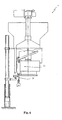
- the diagnostic means also comprise at least one second pressure sensor 35 arranged to intercept a channel 90 of the filling machine 3 in communication with the container in order to make various operating fluids flow into or out of its interior.
- Such sensor detects at least one second measurement value of the pressure in such channel 90 indicative of the passage condition of the aforesaid operating fluid into or from the container associated with the corresponding valve group of the rotary filling machine 3, as schematized in the enclosed figures 4 and 5 .
- the second pressure sensor 35 is a pressure transducer susceptible to detect second data identifying the pressure in the channel 90.
- Each valve group 15 of the isobaric filling machine 3 illustrated in figure 5 preferably comprises an interception valve 40 of a vacuum circuit intended to suction all the air from the container as soon as this is carried by the support plate with the centering cone sealingly on the lip of the supply duct 18.
- a self-leveling step takes place, during which a flow of inert gas, controlled by a valve 41 of a self-leveling circuit, is insufflated into the container in order to determine the ascent in the air return tube (or compensation tube) 19 of the liquid (and foam) portion arranged above the desired level or at the lower mouth of the same air return tube 19.
- the valve 41 of the auto-leveling circuit is connected to the inert gas source and to the container through holes made in the lip around the supply duct 18.
- the aforesaid holes place the container interior in communication with an intermediate poppet valve which, in turn, is in communication with the valve 41 of the self-leveling circuit.
- the poppet valve 7 is in communication with the three valves 40, 41 and 42 of the vacuum, the self-level and the isobaric circuit by means of a common channel 90 indicated in figure 5 in two orthogonal sections that run parallel to the walls of the tank 16.
- the second pressure sensor 35 is for example arranged to intercept the channel 90 in communication with the container in order to detect the pressure at the different operating steps of the isobaric filling machine 3.
- the second pressure sensor 35 is for example arranged to intercept the vacuum duct 44 or the inert gas duct 46 or two second pressure sensors 35 can be provided, each arranged at one of the aforesaid ducts and of course in communication with the logic control unit 32.
- the diagnostic means also comprise at least one third pressure sensor 47 arranged to intercept of the air passage channel 27 of the capping head 21 (as schematized in figure 7 ).
- the third sensor 47 detects a third measurement value of the pressure of the air passage channel at each container.
- the diagnostic means also comprise first inspection means 48 for checking the suitable cleanness of each container; such means are advantageously mounted on the outlet starwheel 69 of the rinsing machine 2, and consist of metallic sensors associated with the bottom of the containers and/or refraction sensors for checking particles in suspension and/or photographic inspection sensors, which were schematically indicated with a small circle in the enclosed figure 1 .
- first inspection means 48 detect a fourth measurement value of the cleanness of each container.
- the diagnostic means also comprise at least second inspection means 50 mounted on the inlet starwheel 51 of the filling machine 3, in particular consisting of cameras; such second means were schematically indicated with a small square in the enclosed figure 1 .
- Such second inspection means 50 detect a fifth measurement value of the shape of the neck of the container for ascertaining the suitability of the container to create a closed chamber in the next rotary filling machine 3.
- the diagnostic means comprise third inspection means 52 mounted on the outlet starwheel 53 of the filling machine; such third inspection means 52 detect a fifth measurement value of the liquid level in the neck of the container, in particular by means of an optical sensor schematically indicated with a star in the enclosed figure 1 that is susceptible to read the diffraction of water.
- the diagnostic means comprise advantageously a first dynamometric sensor 54 adapted to detect the pressure exerted by the sleeve 29 on the mouth of the container and create a sixth measurement value of the force with which the capsule is screwed or pressed against the mouth of the container.
- a first dynamometric sensor 54 will be arranged at an abutment ring of the spring 30 coaxial with the sleeve 29.
- the diagnostic means can comprise a second dynamometric sensor 55 adapted to detect the pressure exerted by the rollers 28 on the neck of the containers moved in rotary motion by the head itself against the capsules for shaping the threads on their flanges by crimping.
- the second dynamometric sensor 55 creates a seventh measurement value of the force with which the capsule is threaded or pressed against the neck of the container.
- such second dynamometric sensor 55 can be arranged at adjustment screws for the pressure of the rollers.
- the plant also advantageously comprises the second capping machine 6 mentioned above, of rotary turntable type carrying a plurality of peripherally-mounted rolling heads, adapted to equip the neck of the containers, in particular of bottles, with capsules adapted to conceal the cap and to constitute a safety seal of the bottle contents.
- the capsules which are fit on the neck of the bottles in the bottling lines can be made of thermo-retractable polymer material, or ductile and deformable materials such as polylaminate, tin or aluminum.
- Each rolling head comprises a rotary body rotatably mounted on the support structure of the head and carrying, pivoted, a plurality of equalizers with respective pressure rollers.
- a plurality of springs are interposed between the equalizers and the annular body in order to elastically force the pressure rollers against the capsules.
- the diagnostic means comprise a third dynamometric sensor analogous to the second and adapted to detect the pressure exerted by the rollers on the neck of the containers and create an eighth measurement value of the force with which the capsule is rolled or pressed against the neck of the container.
- the diagnostic means can also comprise numerous other sensors associated with the devices mounted along the in-line transportation means of the plant 1.
- sensors can be provided able to detect the correct insertion of liquid nitrogen drops following the filling operation of the container with the liquid to be bottled of the relative filling machine 3 and before the capping operation of the relative capping machine 4.
- Also forming the object of the present invention is a process for bottling containers with liquids; such process in particular employs the above-described plant 1, whose reference numbers will be maintained below for the sake of simplicity.
- the process comprises the following operative steps: a rinsing step in which the single containers are separately internally washed in succession by means of a washing fluid; a filling step, after the rinsing step in which the single containers are separately filled in succession by means of a liquid to be bottled; a capping step, after the filling step in which the single containers are capped in succession by means of a cap compressible in the neck of the container or by means of a capsule externally fixable on the neck of said container; a labeling step, after the capping step, in which the single containers are labeled in succession by means of a label.
- the aforesaid succession of rinsing, filling, capping and labeling steps is advantageously controlled by the electronic unit 32 equipped with centralized logic control in order to separately carry out the relative operations on the single containers that move forward in ordered sequence from the inlet section 8 of the plant 1 to the outlet section 9 of the plant 1 through the transportation means 7.
- an indexing step is therefore provided in which a detection sensor 33 arranged in the vicinity of the inlet section 8 to intercept the containers that move forward through the transportation means 7, communicates to the electronic unit 32 the passage the containers.
- the electronic unit 32 consequently assigns each of the containers a sequential identification code.
- At least one data detection step is provided in which the diagnostic means associated with at least one of the machines 2, 3, 4, 5, 6 detect at least one measurement value of at least one of the operations which such machines perform on the single container.
- the control unit 32 then associates the corresponding measurement value received from the diagnostic means with the code of each container, such that in the next labeling step, there occurs the printing - on the label of each container - of the relative identification code and the corresponding measurement value of the diagnostic means on the label of each container.
- the plant and the process, object of the present invention allow attaining numerous advantages.
- the data logging of that which occurred in the process of bottling on the single container allows, at any time, to check the causes of possible defects on the finished product and consequently to arrange the plant or the process in an improved manner.
- the indexing of the single bottle allows avoiding uselessly subjecting the same to steps and machines if it does not meet the conditions to correctly completing its packaging.
- the end client has greater assurance not only regarding the purchased batch, but also the single bottle; this is particularly important where the liquid represents a considerable added value, as is the case with some very expensive wines.
- the finding thus conceived therefore attains the predetermined objects.
Landscapes
- Engineering & Computer Science (AREA)
- Mechanical Engineering (AREA)
- Filling Of Jars Or Cans And Processes For Cleaning And Sealing Jars (AREA)
- External Artificial Organs (AREA)
Claims (12)
- Abfüllanlage für Behälter mit Flüssigkeiten, die Folgendes umfasst:- Transportvorrichtungen (7), die geeignet sind, die Behälter in einer gleichbleibenden Folge auf der gesamten Strecke von einem Eingangsbereich (8) der Anlage zu einem Ausgangsbereich (9) der Anlage zu befördern;- eine Dreh-Abfüllmaschine (3), die die Transportvorrichtungen (7) erfasst und sich nach diesem Eingangsbereich (8) befindet und mit einer Vielzahl von Ventilgruppen (15) ausgestattet ist, die geeignet sind, einen Abfüllvorgang mit einer abzufüllenden Flüssigkeit getrennt auf den einzelnen Behältern durchzuführen;- eine Dreh-Verschlussmaschine (4), die die Transportvorrichtungen (7) erfasst, die sich nach der genannten Abfüllmaschine (3) befindet und mit einer Vielzahl von Verschlussköpfen (21) ausgestattet ist, die geeignet sind, einen Verschließvorgang getrennt auf den einzelnen Behältern durchzuführen;- eine Etikettiermaschine (5), die die Transportvorrichtungen (7) erfasst und sich nach dieser Verschlussmaschine (4) und vor dem genannten Ausgangsbereich (9) befindet, die geeignet ist, einen Etikettiervorgang getrennt auf den einzelnen Behältern durchzuführen;dadurch gekennzeichnet, dass sie Folgendes umfasst:- einen Erfassungssensor (33) in der Nähe des genannten Eingangsbereichs (8) zur Erfassung der Behälter, die über die genannten Transportvorrichtungen (7) in Verbindung mit einem elektronischen Gerät (32) zugeführt werden, das jedem der genannten Behälter einen sequentiellen Identifizierungscode zuweist;- diagnostische Geräte, die mit mindestens einer der genannten Maschinen (3, 4, 5) verbunden und geeignet sind, mindestens einen Messwert mindestens einer der genannten Vorgänge und in Verbindung mit dem genannten elektronischen Gerät (32) zu erfassen; wobei das genannte elektronische Gerät (32) dem Identifizierungscode jedes genannten Behälters den genannten Messwert zuordnet, der von den genannten diagnostischen Geräten empfangen wurde;- wobei sich die genannte Etikettiermaschine (5) mit dem genannten elektronischen Gerät (32) in Verbindung befindet und auf das Etikett jedes genannten Behälters den jeweiligen Identifizierungscode und den entsprechenden Messwert druckt.
- Anlage nach Anspruch 1, die zudem eine Dreh-Spülmaschine (2) zur Erfassung der Transportvorrichtungen (7) umfasst, die mit einer Vielzahl von Spülköpfen ausgestattet ist, die geeignet sind, einen getrennten Spülvorgang auf den einzelnen Behältern auszuführen; wobei die genannte Spülmaschine (2) über eine Vielzahl von Spülgruppen (10) verfügt, die peripher auf einem ersten Karussell montiert sind und jeweils Folgendes umfassen: einen Greifer (11), der auf dem Karussell mit Scharnier angebracht ist und zum Fassen eines zu spülenden Behälters betätigt werden kann und um diesen um 180° zu drehen, um ihn aus einer aufrechten Position in eine umgedrehte Position zu bringen; eine Einspritzdüse (12), die auf dem Karussell mit der Mündung des Behälters in umgedrehter Position ausgerichtet ist und mit einer Versorgungsleitung (13) an ein Ventil (14) zur Ausgabe einer Waschflüssigkeit angeschlossen ist, mit der der genannte Behälter gespült werden soll; wobei die genannten diagnostischen Geräte mindestens einen ersten Drucksensor (34) umfassen, der zur Erfassung der genannten Versorgungsleitung (13) der Waschflüssigkeit dient und sich zwischen der genannten Einspritzdüse (12) und dem genannten Verteilerventil (14) befindet, wobei der genannte erste Sensor (34) einen ersten Messwert des Drucks der genannten Waschflüssigkeit auf jedem Behälter misst.
- Anlage nach Anspruch 1, bei der die genannte Abfüllmaschine (3) ein zweites Drehkarussell umfasst, auf dem ein Tank (16) zur Aufnahme einer abzufüllenden Flüssigkeit montiert ist und eine Vielzahl von Ventilgruppen (15), die peripher auf diesem Dreh-Karussell montiert sind und von denen jede eine Zuleitung (18) umfasst, die hydraulisch an den genannten Tank (16) angeschlossen ist, um die genannte Flüssigkeit aus dem genannten Tank (16) den genannten abzufüllenden Behältern zuzuleiten, eine Luftrückführungskanüle (19), mindestens einen mobilen Verschluss (20) zwischen einer Öffnungs- und einer Schließposition der genannten Zuleitung (18), um den Zufluss der genannten Flüssigkeit in die genannten Behälter zu regeln;
wobei die genannten diagnostischen Geräte mindestens einen zweiten Drucksensor (35) umfassen, der mindestens einen Kanal (90) der genannten Abfüllmaschine (3) in Verbindung mit dem genannten Behälter erfasst; wobei der genannte zweite Sensor (35) mindestens einen zweiten Messwert des Drucks in dem genannten Kanal (90) erfasst, der der entsprechenden Ventilgruppe (15) der genannten Dreh-Abfüllmaschine (3) zugeordnet ist. - Anlage nach Anspruch 3, in der es sich bei dem genannten zweiten Drucksensor (35) um einen Druckwandler handelt, der zweite Identifizierungsdaten des Drucks in dem genannten Behälter messen kann, wobei der genannte Behälter an die genannte Zuleitung (18) angeschlossen ist, d. h., an die Luftauslassvorrichtungen oder aber an Vorrichtungen zum Einspritzen von inertem Gas.
- Anlage nach Anspruch 1, bei der die genannte Verschlussmaschine (4) eine Vielzahl von Verschlussköpfen (21) umfasst, die peripher auf einem dritten Drehkarussell montiert sind und von denen jeder Folgendes umfasst:- Pressvorrichtungen (22), um einen Verschluss (24) von einer breiteren Form in eine komprimierte Form zu bringen, die in die Öffnung eines Behälters eingeführt werden kann;- Schiebevorrichtungen (23), die oberhalb der genannten Pressvorrichtungen (22) montiert sind und betätigt werden können, um den genannten Verschluss (24), der von den genannten Pressvorrichtungen (22) in komprimierter Form gehalten wird, entlang einer Längsachse des Verschließens zumindest teilweise in das Innere des genannten Behälters zu drücken;- eine Fördergruppe (25), die mit Folgendem ausgestattet ist:wobei die genannten diagnostischen Geräte mindestens einen dritten Drucksensor (47) umfassen, der mit dem genannten Luftdurchlasskanal (27) des genannten Verschlusskopfs (21) verbunden ist; wobei dieser genannte dritte Sensor (47) einen dritten Messwert des genannten Luftdurchlasskanals (27) auf jedem der genannten Behälter erfasst.- einer Haltefläche, die als Anschlag der Mündung des genannten Behälters dient;- einem Förderer (26), der unter den genannten Pressvorrichtungen (22) montiert und mit einer Durchgangsöffnung ausgestattet ist, die im Verhältnis zur Achse des Verschließens und der Mündung des genannten Behälters vertikal ausgerichtet und dazu bestimmt ist, den genannten von den Pressvorrichtungen (23) gehaltenen Verschluss in die Mündung des genannten Behälters zu befördern, der auf der genannten Haltefläche aufliegt;- Mindestens einem Luftdurchlasskanal (27), der das Innenvolumen des genannten Behälters, das von dem genannten Verschluss (24) begrenzt wird, der abdichtend in der genannten Durchgangsöffnung positioniert ist, mit Vorrichtungen zum Ansaugen und/oder Einspritzen von inertem Gas verbinden kann;
- Anlage nach Anspruch 2, dadurch gekennzeichnet, dass die genannten Transportvorrichtungen (7) eine Schnecke (7') umfassen, die sich auf dem genannten Eingangsbereich (8) befindet, die der genannten Spülmaschine (2) die genannten Behälter zuführt und auf der der genannte Erfassungssensor (33) montiert ist, der insbesondere aus einer Fotozelle besteht, die den Durchgang der genannten Behälter erfasst und deren Vorliegen dem genannten elektronischen Gerät (32) zur Vergabe des genannten Identifizierungscode mitteilt; wobei es sich bei dem genannten elektronischen Gerät (32) um ein zentrales elektronisches Steuergerät handelt, das an die genannten Maschinen (2, 3, 4, 5) angeschlossen ist, um diese mit zuvor festgelegten Betriebsmodi der Reihenfolge nach auf den einzelnen Behältern zu steuern und die Zuleitung der Waschflüssigkeit von Seiten des Verteilerventils (14) der genannten Spülmaschine (2) auf dem von dem entsprechenden Code identifizierten Behälter zu aktivieren.
- Anlage nach Anspruch 2, dadurch gekennzeichnet, dass die genannten diagnostischen Geräte erste Inspektionsvorrichtungen (4) umfassen, um die geeignete Sauberkeit eines jeden genannten Behälters zu überprüfen, die bequem auf einem Ausgangsstern (69) der genannten Spülmaschine (2) montiert sind, die insbesondere aus Metallsensoren bestehen, die am Boden der genannten Behälter angebracht sind und/oder aus Refraktionssensoren, um schwebende Partikel zu überprüfen und/oder aus fotografischen Inspektionssensoren; wobei die ersten Inspektionsvorrichtungen (48) einen vierten Messwert der Sauberkeit eines jeden genannten Behälters erfassen.
- Anlage nach Anspruch 1, dadurch gekennzeichnet, dass die genannten diagnostischen Geräte zweite Inspektionsvorrichtungen (50) umfassen, die auf einem Eingangsstern (51) der genannten Abfüllmaschine (3) montiert sind, die insbesondere aus Kameras bestehen, wobei die genannten zweiten Inspektionsvorrichtungen (50) einen fünften Messwert der Form des Flaschenhalses messen, um die Eignung zur Schaffung einer geschlossenen Kammer in der nachfolgenden Dreh-Abfüllmaschine (3) festzustellen.
- Anlage nach Anspruch 1, dadurch gekennzeichnet, dass die genannten diagnostischen Geräte dritte Inspektionsvorrichtungen (52) umfassen, die auf einem Ausgangsstern (53) der genannten Abfüllmaschine (3) montiert sind, wobei die genannten dritten Inspektionsvorrichtungen (52) insbesondere anhand eines optischen Sensors, der die Diffraktion des Wassers ablesen kann, einen fünften Messwert des Füllstands der Flüssigkeit im Hals des genannten Behälters erfassen.
- Anlage nach Anspruch 1, bei der die genannte Verschlussmaschine (4) ein drittes Drehkarussell umfasst, auf dem peripher zwei oder mehrere Arbeitsköpfe (21') montiert sind, die betätigt werden können, um zwischen einer ersten angehobenen Position, in der es sich oberhalb der Kapsel auf dem Kopf der genannten Behälter befindet, und einer ersten gesenkten Position, bei der es auf den Kopf der genannten Behälter gesenkt ist und über ein zentrales Rohr (29) die genannten Kapsel auf die Mündung des genannten Behälters presst, verschoben zu werden;
wobei die diagnostischen Geräte mindestens einen ersten dynamometrischen Sensor (54) umfassen, der geeignet ist, den auf das genannte Rohr (29) auf der Mündung des genannten Behälters ausgeübten Druck zu messen. - Anlage nach Anspruch 10, bei der die genannte Verschlussmaschine (4) zudem einen Drehkörper umfasst, der drehbar um eine Längsachse montiert ist; eine Vielzahl Stangen (31), die auf dem genannten Drehkörper angeordnet sind und auf denen entsprechende Rollen (28) montiert sind, die geeignet sind, einen Druck auf die auf der Mündung des genannten Behälters montierte Kapsel auszuüben; wobei die genannten diagnostischen Geräte einen zweiten dynamometrischen Sensor (55) umfassen, der geeignet ist, den von den genannten Rollen (28) auf den genannten Behälter ausgeübten Druck zu messen.
- Abfüllverfahren für Behälter mit Flüssigkeiten, das die folgenden Arbeitsschritte umfasst:- einen Abfüllschritt, bei dem die einzelnen Behälter getrennt nacheinander mit einer abzufüllenden Flüssigkeit gefüllt werden;- einen Verschlussschritt, der auf den genannten Abfüllschritt folgt, bei dem die einzelnen Behälter nacheinander mit einem komprimierbaren Verschluss im Hals des genannten Behälters oder einer außen auf dem Hals des genannten Behälters zu befestigenden Kapsel verschlossen werden;- einen Etikettierschritt, der auf den genannten Verschlussschritt folgt, bei dem die einzelnen Behälter nacheinander mit einem Etikett versehen werden;wobei die genannte Folge des Abfüllens, Verschließens und Etikettierens nacheinander auf den einzelnen Behältern erfolgt, die in geordneter Reihenfolge anhand von Transportvorrichtungen (7) von einem Eingangsbereich (8) der Anlage zu einem Ausgangsbereich (9) der Anlage befördert werden;
dadurch gekennzeichnet, dass sie Folgendes umfasst:- einen Indexierungsschritt, bei dem ein Erfassungssensor (33) in der Nähe des genannten Eingangsbereichs (8) zur Erfassung der Behälter, die mittels der genannten Transportvorrichtungen (7) befördert werden, einem elektronischen Gerät (32) den Durchgang der genannten Behälter mitteilt und das genannte elektronische Gerät (32) folglich an jeden von ihnen einen sequentiellen Identifizierungscode vergibt;- einen Datenerfassungsschritt, bei dem die mit mindestens einer der genannten Maschinen (3, 4, 5) verbundenen diagnostischen Geräte mindestens einen Messwert mindestens einer der genannten Vorgänge erfassen; wobei das genannte elektronische Gerät (32) dem Identifizierungscode jedes genannten Behälters den genannten Messwert zuordnet, der von den genannten diagnostischen Geräten empfangen wurde;wobei bei dem genannten Etikettierschritt auf das Etikett jedes Behälters der jeweilige Identifizierungscodes und der entsprechende Messwert aufgedruckt werden, die von dem genannten elektronischen Gerät miteinander assoziiert wurden.
Priority Applications (1)
| Application Number | Priority Date | Filing Date | Title |
|---|---|---|---|
| SI201230012T SI2594499T1 (sl) | 2011-11-15 | 2012-11-15 | Linijski polnilni postroj za vsebnike s tekočino in polnilni proces |
Applications Claiming Priority (1)
| Application Number | Priority Date | Filing Date | Title |
|---|---|---|---|
| IT000357A ITPD20110357A1 (it) | 2011-11-15 | 2011-11-15 | Impianto di imbottigliamento in linea di contenitori con liquidi e procedimento di imbottigliamento, in particolare mediante detto impianto. |
Publications (2)
| Publication Number | Publication Date |
|---|---|
| EP2594499A1 EP2594499A1 (de) | 2013-05-22 |
| EP2594499B1 true EP2594499B1 (de) | 2013-09-18 |
Family
ID=45491697
Family Applications (1)
| Application Number | Title | Priority Date | Filing Date |
|---|---|---|---|
| EP20120192884 Active EP2594499B1 (de) | 2011-11-15 | 2012-11-15 | Inline-Abfüllanlagen für Behälter mit Flüssigkeiten und Abfüllverfahren |
Country Status (3)
| Country | Link |
|---|---|
| EP (1) | EP2594499B1 (de) |
| IT (1) | ITPD20110357A1 (de) |
| SI (1) | SI2594499T1 (de) |
Families Citing this family (8)
| Publication number | Priority date | Publication date | Assignee | Title |
|---|---|---|---|---|
| CN104986389B (zh) * | 2015-07-16 | 2017-10-31 | 无锡中营康园自动化设备有限公司 | 全自动饮料灌装机 |
| ITUB20152717A1 (it) * | 2015-07-31 | 2017-01-31 | Phizero S R L | Sistema per preparare un contentitore contenente una sostanza attiva |
| US11261072B2 (en) | 2016-09-26 | 2022-03-01 | Dai Nippon Printing Co., Ltd. | Aseptic filling machine and aseptic filling method |
| IT201700081876A1 (it) * | 2017-07-19 | 2019-01-19 | Gruppo Bisaro Sifa Srl | Dispositivo e procedimento per lavare contenitori per liquidi alimentari o filtri per bevande fermentate. |
| CN108545688B (zh) * | 2018-05-28 | 2024-03-08 | 江苏兆恒机械科技有限公司 | 四合一洗灌旋一体机 |
| DE102018210821A1 (de) * | 2018-07-02 | 2020-01-02 | Krones Ag | Verfahren zum Kommissionieren von Paletten mit Getränkegebinden |
| CN109105047B (zh) * | 2018-07-14 | 2023-09-08 | 福建农林大学 | 用于研究根系亲缘识别的试验装置及其工作方法 |
| CN111470463A (zh) * | 2020-05-26 | 2020-07-31 | 江苏威龙智能科技股份有限公司 | 一种无菌滴眼液瓶灌装生产线 |
Family Cites Families (4)
| Publication number | Priority date | Publication date | Assignee | Title |
|---|---|---|---|---|
| DE102004005382A1 (de) * | 2004-02-03 | 2005-09-01 | Endress + Hauser Flowtec Ag, Reinach | Verfahren zum Abfüllen eines Mediums |
| DE102008012505B4 (de) * | 2008-03-04 | 2019-02-21 | Krones Aktiengesellschaft | Streckblasmaschine mit Druckeinrichtung |
| DE102009040977B4 (de) * | 2009-09-11 | 2022-12-15 | Krones Aktiengesellschaft | Behältnisbehandlungsanlage und ein Behältnisbehandlungsverfahren zum Behandeln von mit einem Produkt befüllbaren Behältnissen |
| IT1395607B1 (it) * | 2009-09-14 | 2012-10-16 | Ft System Srl | Impianto di riempimento di bottiglie o contenitori a taratura continua e metodo di taratura in continuo di un tale impianto |
-
2011
- 2011-11-15 IT IT000357A patent/ITPD20110357A1/it unknown
-
2012
- 2012-11-15 EP EP20120192884 patent/EP2594499B1/de active Active
- 2012-11-15 SI SI201230012T patent/SI2594499T1/sl unknown
Also Published As
| Publication number | Publication date |
|---|---|
| SI2594499T1 (sl) | 2014-01-31 |
| ITPD20110357A1 (it) | 2013-05-16 |
| EP2594499A1 (de) | 2013-05-22 |
Similar Documents
| Publication | Publication Date | Title |
|---|---|---|
| EP2594499B1 (de) | Inline-Abfüllanlagen für Behälter mit Flüssigkeiten und Abfüllverfahren | |
| US6474368B2 (en) | Beverage container filling machine, and method for filling containers with a liquid filling material in a beverage container filling machine | |
| US6470922B2 (en) | Bottling plant for bottling carbonated beverages | |
| CN103496481B (zh) | 容器处理设备和容器处理方法 | |
| US6463964B2 (en) | Method of operating a machine for filling bottles, cans or the like beverage containers with a beverage, and a beverage container filling machine | |
| US6494238B2 (en) | Plant for filling beverage into beverage bottles and other beverage containers having apparatus for replacing remaining air volume in filled beverage bottles or other beverage containers | |
| CA2488897C (en) | System for filling and closing fluid containing cartridges | |
| US9375878B2 (en) | Method and apparatus for operating a plant for the treatment of containers with superordinated choice of parameters | |
| US20180037357A1 (en) | Beverage bottling plant having an information adding station for adding information to bottles and a method of operating a beverage bottling plant information adding station | |
| CN103159156A (zh) | 用于封闭或装填容器的旋转机 | |
| US20020073652A1 (en) | Bottling plant and method of operating a bottling plant and a bottling plant with sections for stabilizing the bottled product | |
| US7814939B2 (en) | Method of operating a beverage bottling plant with a beverage filling machine for filling beverage bottles, and a method and apparatus for monitoring beverage bottle or container handling machines in the beverage bottling plant | |
| US20070193223A1 (en) | Beverage bottling plant for filling bottles with a liquid beverage filling material having an information adding station | |
| US20120032364A1 (en) | Method and Apparatus for Operating a Plant for the Treatment of Containers with Controlled Parameter Selection | |
| EP3386905B1 (de) | Maschine zum befüllen von flaschen dosen und ähnliche behälter | |
| US20070163213A1 (en) | Beverage bottling plant for filling beverage bottles with a liquid beverage material and a method of operation thereof | |
| JPH07500289A (ja) | 容器用連続作業検査機 | |
| ITUB201568811U1 (it) | Impianto di imbottigliamento di contenitori con liquidi | |
| US20080314476A1 (en) | Beverage bottling plant for filling bottles with a liquid beverage material | |
| US7299607B2 (en) | Beverage bottling plant for filling bottles with a liquid beverage, having a filling element for filling bottles with a liquid beverage and a filling machine having such a filling element | |
| CN115996886A (zh) | 用于产品容器的处理设备和处理方法 | |
| US7162849B2 (en) | Beverage bottling plant for filling bottles with a liquid beverage material having a bottle closing device, and a closure applying machine for closing of containers, such as bottles, cans, canisters, or the like, by way of screwing on of screw caps | |
| US7845148B2 (en) | Method and apparatus for insertion of uniquely shaped packaging elements | |
| CN113753836A (zh) | 用于用尤其是饮料的液体物质灌装两种不同类型的容器的机器 | |
| US9873536B2 (en) | Container handling machine and method |
Legal Events
| Date | Code | Title | Description |
|---|---|---|---|
| PUAI | Public reference made under article 153(3) epc to a published international application that has entered the european phase |
Free format text: ORIGINAL CODE: 0009012 |
|
| 17P | Request for examination filed |
Effective date: 20130313 |
|
| AK | Designated contracting states |
Kind code of ref document: A1 Designated state(s): AL AT BE BG CH CY CZ DE DK EE ES FI FR GB GR HR HU IE IS IT LI LT LU LV MC MK MT NL NO PL PT RO RS SE SI SK SM TR |
|
| AX | Request for extension of the european patent |
Extension state: BA ME |
|
| GRAP | Despatch of communication of intention to grant a patent |
Free format text: ORIGINAL CODE: EPIDOSNIGR1 |
|
| RIC1 | Information provided on ipc code assigned before grant |
Ipc: B67B 3/26 20060101ALI20130627BHEP Ipc: B65C 9/46 20060101AFI20130627BHEP Ipc: B67C 7/00 20060101ALI20130627BHEP Ipc: B67C 3/00 20060101ALI20130627BHEP |
|
| GRAS | Grant fee paid |
Free format text: ORIGINAL CODE: EPIDOSNIGR3 |
|
| INTG | Intention to grant announced |
Effective date: 20130718 |
|
| GRAA | (expected) grant |
Free format text: ORIGINAL CODE: 0009210 |
|
| AK | Designated contracting states |
Kind code of ref document: B1 Designated state(s): AL AT BE BG CH CY CZ DE DK EE ES FI FR GB GR HR HU IE IS IT LI LT LU LV MC MK MT NL NO PL PT RO RS SE SI SK SM TR |
|
| REG | Reference to a national code |
Ref country code: GB Ref legal event code: FG4D |
|
| REG | Reference to a national code |
Ref country code: CH Ref legal event code: EP |
|
| REG | Reference to a national code |
Ref country code: IE Ref legal event code: FG4D |
|
| REG | Reference to a national code |
Ref country code: AT Ref legal event code: REF Ref document number: 632608 Country of ref document: AT Kind code of ref document: T Effective date: 20131015 |
|
| REG | Reference to a national code |
Ref country code: DE Ref legal event code: R096 Ref document number: 602012000318 Country of ref document: DE Effective date: 20131114 |
|
| PG25 | Lapsed in a contracting state [announced via postgrant information from national office to epo] |
Ref country code: HR Free format text: LAPSE BECAUSE OF FAILURE TO SUBMIT A TRANSLATION OF THE DESCRIPTION OR TO PAY THE FEE WITHIN THE PRESCRIBED TIME-LIMIT Effective date: 20130918 Ref country code: SE Free format text: LAPSE BECAUSE OF FAILURE TO SUBMIT A TRANSLATION OF THE DESCRIPTION OR TO PAY THE FEE WITHIN THE PRESCRIBED TIME-LIMIT Effective date: 20130918 Ref country code: CY Free format text: LAPSE BECAUSE OF FAILURE TO SUBMIT A TRANSLATION OF THE DESCRIPTION OR TO PAY THE FEE WITHIN THE PRESCRIBED TIME-LIMIT Effective date: 20130918 Ref country code: NO Free format text: LAPSE BECAUSE OF FAILURE TO SUBMIT A TRANSLATION OF THE DESCRIPTION OR TO PAY THE FEE WITHIN THE PRESCRIBED TIME-LIMIT Effective date: 20131218 Ref country code: LT Free format text: LAPSE BECAUSE OF FAILURE TO SUBMIT A TRANSLATION OF THE DESCRIPTION OR TO PAY THE FEE WITHIN THE PRESCRIBED TIME-LIMIT Effective date: 20130918 |
|
| REG | Reference to a national code |
Ref country code: NL Ref legal event code: VDEP Effective date: 20130918 |
|
| REG | Reference to a national code |
Ref country code: AT Ref legal event code: MK05 Ref document number: 632608 Country of ref document: AT Kind code of ref document: T Effective date: 20130918 |
|
| REG | Reference to a national code |
Ref country code: LT Ref legal event code: MG4D |
|
| PG25 | Lapsed in a contracting state [announced via postgrant information from national office to epo] |
Ref country code: GR Free format text: LAPSE BECAUSE OF FAILURE TO SUBMIT A TRANSLATION OF THE DESCRIPTION OR TO PAY THE FEE WITHIN THE PRESCRIBED TIME-LIMIT Effective date: 20131219 Ref country code: LV Free format text: LAPSE BECAUSE OF FAILURE TO SUBMIT A TRANSLATION OF THE DESCRIPTION OR TO PAY THE FEE WITHIN THE PRESCRIBED TIME-LIMIT Effective date: 20130918 Ref country code: RS Free format text: LAPSE BECAUSE OF FAILURE TO SUBMIT A TRANSLATION OF THE DESCRIPTION OR TO PAY THE FEE WITHIN THE PRESCRIBED TIME-LIMIT Effective date: 20130918 Ref country code: FI Free format text: LAPSE BECAUSE OF FAILURE TO SUBMIT A TRANSLATION OF THE DESCRIPTION OR TO PAY THE FEE WITHIN THE PRESCRIBED TIME-LIMIT Effective date: 20130918 |
|
| PG25 | Lapsed in a contracting state [announced via postgrant information from national office to epo] |
Ref country code: BE Free format text: LAPSE BECAUSE OF FAILURE TO SUBMIT A TRANSLATION OF THE DESCRIPTION OR TO PAY THE FEE WITHIN THE PRESCRIBED TIME-LIMIT Effective date: 20130918 |
|
| PG25 | Lapsed in a contracting state [announced via postgrant information from national office to epo] |
Ref country code: CZ Free format text: LAPSE BECAUSE OF FAILURE TO SUBMIT A TRANSLATION OF THE DESCRIPTION OR TO PAY THE FEE WITHIN THE PRESCRIBED TIME-LIMIT Effective date: 20130918 Ref country code: NL Free format text: LAPSE BECAUSE OF FAILURE TO SUBMIT A TRANSLATION OF THE DESCRIPTION OR TO PAY THE FEE WITHIN THE PRESCRIBED TIME-LIMIT Effective date: 20130918 Ref country code: EE Free format text: LAPSE BECAUSE OF FAILURE TO SUBMIT A TRANSLATION OF THE DESCRIPTION OR TO PAY THE FEE WITHIN THE PRESCRIBED TIME-LIMIT Effective date: 20130918 Ref country code: SK Free format text: LAPSE BECAUSE OF FAILURE TO SUBMIT A TRANSLATION OF THE DESCRIPTION OR TO PAY THE FEE WITHIN THE PRESCRIBED TIME-LIMIT Effective date: 20130918 Ref country code: IS Free format text: LAPSE BECAUSE OF FAILURE TO SUBMIT A TRANSLATION OF THE DESCRIPTION OR TO PAY THE FEE WITHIN THE PRESCRIBED TIME-LIMIT Effective date: 20140118 |
|
| PG25 | Lapsed in a contracting state [announced via postgrant information from national office to epo] |
Ref country code: ES Free format text: LAPSE BECAUSE OF FAILURE TO SUBMIT A TRANSLATION OF THE DESCRIPTION OR TO PAY THE FEE WITHIN THE PRESCRIBED TIME-LIMIT Effective date: 20130918 Ref country code: PL Free format text: LAPSE BECAUSE OF FAILURE TO SUBMIT A TRANSLATION OF THE DESCRIPTION OR TO PAY THE FEE WITHIN THE PRESCRIBED TIME-LIMIT Effective date: 20130918 Ref country code: AT Free format text: LAPSE BECAUSE OF FAILURE TO SUBMIT A TRANSLATION OF THE DESCRIPTION OR TO PAY THE FEE WITHIN THE PRESCRIBED TIME-LIMIT Effective date: 20130918 |
|
| REG | Reference to a national code |
Ref country code: DE Ref legal event code: R097 Ref document number: 602012000318 Country of ref document: DE |
|
| PG25 | Lapsed in a contracting state [announced via postgrant information from national office to epo] |
Ref country code: PT Free format text: LAPSE BECAUSE OF FAILURE TO SUBMIT A TRANSLATION OF THE DESCRIPTION OR TO PAY THE FEE WITHIN THE PRESCRIBED TIME-LIMIT Effective date: 20140120 |
|
| PLBE | No opposition filed within time limit |
Free format text: ORIGINAL CODE: 0009261 |
|
| STAA | Information on the status of an ep patent application or granted ep patent |
Free format text: STATUS: NO OPPOSITION FILED WITHIN TIME LIMIT |
|
| PG25 | Lapsed in a contracting state [announced via postgrant information from national office to epo] |
Ref country code: MC Free format text: LAPSE BECAUSE OF FAILURE TO SUBMIT A TRANSLATION OF THE DESCRIPTION OR TO PAY THE FEE WITHIN THE PRESCRIBED TIME-LIMIT Effective date: 20130918 |
|
| 26N | No opposition filed |
Effective date: 20140619 |
|
| PG25 | Lapsed in a contracting state [announced via postgrant information from national office to epo] |
Ref country code: DK Free format text: LAPSE BECAUSE OF FAILURE TO SUBMIT A TRANSLATION OF THE DESCRIPTION OR TO PAY THE FEE WITHIN THE PRESCRIBED TIME-LIMIT Effective date: 20130918 |
|
| REG | Reference to a national code |
Ref country code: DE Ref legal event code: R097 Ref document number: 602012000318 Country of ref document: DE Effective date: 20140619 |
|
| PG25 | Lapsed in a contracting state [announced via postgrant information from national office to epo] |
Ref country code: HU Free format text: LAPSE BECAUSE OF FAILURE TO SUBMIT A TRANSLATION OF THE DESCRIPTION OR TO PAY THE FEE WITHIN THE PRESCRIBED TIME-LIMIT; INVALID AB INITIO Effective date: 20121115 |
|
| REG | Reference to a national code |
Ref country code: IE Ref legal event code: MM4A |
|
| PG25 | Lapsed in a contracting state [announced via postgrant information from national office to epo] |
Ref country code: IE Free format text: LAPSE BECAUSE OF NON-PAYMENT OF DUE FEES Effective date: 20141115 |
|
| REG | Reference to a national code |
Ref country code: FR Ref legal event code: PLFP Year of fee payment: 4 |
|
| PG25 | Lapsed in a contracting state [announced via postgrant information from national office to epo] |
Ref country code: RO Free format text: LAPSE BECAUSE OF FAILURE TO SUBMIT A TRANSLATION OF THE DESCRIPTION OR TO PAY THE FEE WITHIN THE PRESCRIBED TIME-LIMIT Effective date: 20130918 |
|
| PG25 | Lapsed in a contracting state [announced via postgrant information from national office to epo] |
Ref country code: BG Free format text: LAPSE BECAUSE OF FAILURE TO SUBMIT A TRANSLATION OF THE DESCRIPTION OR TO PAY THE FEE WITHIN THE PRESCRIBED TIME-LIMIT Effective date: 20130918 |
|
| REG | Reference to a national code |
Ref country code: CH Ref legal event code: PL |
|
| PG25 | Lapsed in a contracting state [announced via postgrant information from national office to epo] |
Ref country code: LU Free format text: LAPSE BECAUSE OF NON-PAYMENT OF DUE FEES Effective date: 20131115 Ref country code: LI Free format text: LAPSE BECAUSE OF NON-PAYMENT OF DUE FEES Effective date: 20151130 Ref country code: CH Free format text: LAPSE BECAUSE OF NON-PAYMENT OF DUE FEES Effective date: 20151130 Ref country code: TR Free format text: LAPSE BECAUSE OF FAILURE TO SUBMIT A TRANSLATION OF THE DESCRIPTION OR TO PAY THE FEE WITHIN THE PRESCRIBED TIME-LIMIT Effective date: 20130918 Ref country code: MT Free format text: LAPSE BECAUSE OF FAILURE TO SUBMIT A TRANSLATION OF THE DESCRIPTION OR TO PAY THE FEE WITHIN THE PRESCRIBED TIME-LIMIT Effective date: 20130918 |
|
| REG | Reference to a national code |
Ref country code: FR Ref legal event code: PLFP Year of fee payment: 5 |
|
| GBPC | Gb: european patent ceased through non-payment of renewal fee |
Effective date: 20161115 |
|
| PG25 | Lapsed in a contracting state [announced via postgrant information from national office to epo] |
Ref country code: SM Free format text: LAPSE BECAUSE OF FAILURE TO SUBMIT A TRANSLATION OF THE DESCRIPTION OR TO PAY THE FEE WITHIN THE PRESCRIBED TIME-LIMIT Effective date: 20130918 |
|
| REG | Reference to a national code |
Ref country code: FR Ref legal event code: PLFP Year of fee payment: 6 |
|
| PG25 | Lapsed in a contracting state [announced via postgrant information from national office to epo] |
Ref country code: GB Free format text: LAPSE BECAUSE OF NON-PAYMENT OF DUE FEES Effective date: 20161115 |
|
| PG25 | Lapsed in a contracting state [announced via postgrant information from national office to epo] |
Ref country code: MK Free format text: LAPSE BECAUSE OF FAILURE TO SUBMIT A TRANSLATION OF THE DESCRIPTION OR TO PAY THE FEE WITHIN THE PRESCRIBED TIME-LIMIT Effective date: 20130918 |
|
| PG25 | Lapsed in a contracting state [announced via postgrant information from national office to epo] |
Ref country code: AL Free format text: LAPSE BECAUSE OF FAILURE TO SUBMIT A TRANSLATION OF THE DESCRIPTION OR TO PAY THE FEE WITHIN THE PRESCRIBED TIME-LIMIT Effective date: 20130918 |
|
| PGFP | Annual fee paid to national office [announced via postgrant information from national office to epo] |
Ref country code: SI Payment date: 20191021 Year of fee payment: 8 |
|
| PG25 | Lapsed in a contracting state [announced via postgrant information from national office to epo] |
Ref country code: SI Free format text: LAPSE BECAUSE OF NON-PAYMENT OF DUE FEES Effective date: 20201116 |
|
| REG | Reference to a national code |
Ref country code: SI Ref legal event code: KO00 Effective date: 20210812 |
|
| P01 | Opt-out of the competence of the unified patent court (upc) registered |
Effective date: 20230306 |
|
| PGFP | Annual fee paid to national office [announced via postgrant information from national office to epo] |
Ref country code: DE Payment date: 20251119 Year of fee payment: 14 |
|
| PGFP | Annual fee paid to national office [announced via postgrant information from national office to epo] |
Ref country code: IT Payment date: 20251126 Year of fee payment: 14 |
|
| PGFP | Annual fee paid to national office [announced via postgrant information from national office to epo] |
Ref country code: FR Payment date: 20251125 Year of fee payment: 14 |