EP2594765A2 - Compresseur avec un circuit de refroidissement et procédé de refroidissement correspondant - Google Patents
Compresseur avec un circuit de refroidissement et procédé de refroidissement correspondant Download PDFInfo
- Publication number
- EP2594765A2 EP2594765A2 EP12192418.7A EP12192418A EP2594765A2 EP 2594765 A2 EP2594765 A2 EP 2594765A2 EP 12192418 A EP12192418 A EP 12192418A EP 2594765 A2 EP2594765 A2 EP 2594765A2
- Authority
- EP
- European Patent Office
- Prior art keywords
- compressor
- working fluid
- stages
- stage
- bypass path
- Prior art date
- Legal status (The legal status is an assumption and is not a legal conclusion. Google has not performed a legal analysis and makes no representation as to the accuracy of the status listed.)
- Withdrawn
Links
- 238000001816 cooling Methods 0.000 title claims abstract description 19
- 239000012530 fluid Substances 0.000 claims abstract description 69
- 238000010926 purge Methods 0.000 claims abstract description 24
- 238000000034 method Methods 0.000 claims abstract description 23
- 238000011144 upstream manufacturing Methods 0.000 claims abstract description 20
- 230000006835 compression Effects 0.000 claims abstract description 5
- 238000007906 compression Methods 0.000 claims abstract description 5
- 239000000463 material Substances 0.000 description 4
- 230000000694 effects Effects 0.000 description 3
- 239000000446 fuel Substances 0.000 description 3
- 238000013459 approach Methods 0.000 description 2
- 238000002485 combustion reaction Methods 0.000 description 2
- 230000035882 stress Effects 0.000 description 2
- 230000008646 thermal stress Effects 0.000 description 2
- 239000012809 cooling fluid Substances 0.000 description 1
- 230000002708 enhancing effect Effects 0.000 description 1
- 238000013021 overheating Methods 0.000 description 1
- 238000010248 power generation Methods 0.000 description 1
- 230000003068 static effect Effects 0.000 description 1
Images


Classifications
-
- F—MECHANICAL ENGINEERING; LIGHTING; HEATING; WEAPONS; BLASTING
- F02—COMBUSTION ENGINES; HOT-GAS OR COMBUSTION-PRODUCT ENGINE PLANTS
- F02C—GAS-TURBINE PLANTS; AIR INTAKES FOR JET-PROPULSION PLANTS; CONTROLLING FUEL SUPPLY IN AIR-BREATHING JET-PROPULSION PLANTS
- F02C7/00—Features, components parts, details or accessories, not provided for in, or of interest apart form groups F02C1/00 - F02C6/00; Air intakes for jet-propulsion plants
- F02C7/12—Cooling of plants
-
- F—MECHANICAL ENGINEERING; LIGHTING; HEATING; WEAPONS; BLASTING
- F01—MACHINES OR ENGINES IN GENERAL; ENGINE PLANTS IN GENERAL; STEAM ENGINES
- F01D—NON-POSITIVE DISPLACEMENT MACHINES OR ENGINES, e.g. STEAM TURBINES
- F01D17/00—Regulating or controlling by varying flow
- F01D17/10—Final actuators
- F01D17/105—Final actuators by passing part of the fluid
-
- F—MECHANICAL ENGINEERING; LIGHTING; HEATING; WEAPONS; BLASTING
- F02—COMBUSTION ENGINES; HOT-GAS OR COMBUSTION-PRODUCT ENGINE PLANTS
- F02C—GAS-TURBINE PLANTS; AIR INTAKES FOR JET-PROPULSION PLANTS; CONTROLLING FUEL SUPPLY IN AIR-BREATHING JET-PROPULSION PLANTS
- F02C6/00—Plural gas-turbine plants; Combinations of gas-turbine plants with other apparatus; Adaptations of gas-turbine plants for special use
- F02C6/04—Gas-turbine plants providing heated or pressurised working fluid for other apparatus, e.g. without mechanical power output
- F02C6/06—Gas-turbine plants providing heated or pressurised working fluid for other apparatus, e.g. without mechanical power output providing compressed gas
- F02C6/08—Gas-turbine plants providing heated or pressurised working fluid for other apparatus, e.g. without mechanical power output providing compressed gas the gas being bled from the gas-turbine compressor
-
- F—MECHANICAL ENGINEERING; LIGHTING; HEATING; WEAPONS; BLASTING
- F02—COMBUSTION ENGINES; HOT-GAS OR COMBUSTION-PRODUCT ENGINE PLANTS
- F02C—GAS-TURBINE PLANTS; AIR INTAKES FOR JET-PROPULSION PLANTS; CONTROLLING FUEL SUPPLY IN AIR-BREATHING JET-PROPULSION PLANTS
- F02C7/00—Features, components parts, details or accessories, not provided for in, or of interest apart form groups F02C1/00 - F02C6/00; Air intakes for jet-propulsion plants
- F02C7/12—Cooling of plants
- F02C7/16—Cooling of plants characterised by cooling medium
- F02C7/18—Cooling of plants characterised by cooling medium the medium being gaseous, e.g. air
-
- F—MECHANICAL ENGINEERING; LIGHTING; HEATING; WEAPONS; BLASTING
- F02—COMBUSTION ENGINES; HOT-GAS OR COMBUSTION-PRODUCT ENGINE PLANTS
- F02C—GAS-TURBINE PLANTS; AIR INTAKES FOR JET-PROPULSION PLANTS; CONTROLLING FUEL SUPPLY IN AIR-BREATHING JET-PROPULSION PLANTS
- F02C9/00—Controlling gas-turbine plants; Controlling fuel supply in air- breathing jet-propulsion plants
- F02C9/16—Control of working fluid flow
- F02C9/18—Control of working fluid flow by bleeding, bypassing or acting on variable working fluid interconnections between turbines or compressors or their stages
-
- F—MECHANICAL ENGINEERING; LIGHTING; HEATING; WEAPONS; BLASTING
- F04—POSITIVE - DISPLACEMENT MACHINES FOR LIQUIDS; PUMPS FOR LIQUIDS OR ELASTIC FLUIDS
- F04D—NON-POSITIVE-DISPLACEMENT PUMPS
- F04D29/00—Details, component parts, or accessories
- F04D29/26—Rotors specially for elastic fluids
- F04D29/32—Rotors specially for elastic fluids for axial flow pumps
- F04D29/321—Rotors specially for elastic fluids for axial flow pumps for axial flow compressors
-
- F—MECHANICAL ENGINEERING; LIGHTING; HEATING; WEAPONS; BLASTING
- F04—POSITIVE - DISPLACEMENT MACHINES FOR LIQUIDS; PUMPS FOR LIQUIDS OR ELASTIC FLUIDS
- F04D—NON-POSITIVE-DISPLACEMENT PUMPS
- F04D29/00—Details, component parts, or accessories
- F04D29/58—Cooling; Heating; Diminishing heat transfer
- F04D29/582—Cooling; Heating; Diminishing heat transfer specially adapted for elastic fluid pumps
- F04D29/584—Cooling; Heating; Diminishing heat transfer specially adapted for elastic fluid pumps cooling or heating the machine
Definitions
- the subject matter disclosed herein relates generally to a compressor having a purge circuit and methods of purging (cooling) a compressor. More particularly, the subject matter disclosed herein relates to a purge circuit, and methods of using that purge circuit, for controlling thermally induced stresses in an aft end of a compressor.
- a compressor is coupled to a turbine to provide compressed air for enhanced combustion of the gas fuel in a combustor.
- the compressor is subject to operating temperatures that can induce thermal stresses on the compressor material.
- the compressor's components are subject to low cycle fatigue (LCF), embrittlement and creep issues, which can negatively affect the performance of the gas turbine system.
- the invention resides in a compressor including a rotor having a plurality of stages, each of the plurality of stages including a set of radially extending rotor wheels; a working fluid supply path for providing working fluid to each of the plurality of stages for compression by each set of radially extending rotor wheels; a purge circuit for diverting a first portion of the working fluid from an upstream portion of the working fluid supply path to at least one downstream stage of the plurality of stages; and a substantially axial bypass path bypassing the at least one downstream stage, the substantially axial bypass path for diverting a second portion of the working fluid around the at least one downstream stage.
- Another aspect of the invention includes a gas turbine system having: a turbine; and a compressor fluidly connected to the turbine, the compressor as described above.
- In yet another aspect of the invention includes a method of cooling a compressor, the method including: providing working fluid to each of a plurality of stages in the compressor from a working fluid supply path; diverting a first portion of the working fluid from an upstream portion of the working fluid supply path to at least one downstream stage of the plurality of stages; and diverting a second portion of the working fluid around the at least one downstream stage.
- the subject matter disclosed herein relates generally to a compressor purge circuit and methods of purging (cooling) a compressor. More particularly, the subject matter disclosed herein relates to a purge circuit, and methods of using that purge circuit, for controlling thermally induced stresses in the aft end of a compressor.
- a compressor is coupled to a turbine to provide compressed air for enhanced combustion of the gas fuel in a combustor.
- the compressor is subject to operating temperatures that can induce thermal stresses on the compressor material.
- the compressor's components are subject to low cycle fatigue (LCF), embrittlement and creep issues, which can negatively affect the performance of the gas turbine system.
- areas at the aft (or, back, or discharge) end of the compressor are subject to high temperatures, pressures and air flow rates due to their proximity to the exhaust of the compressor. The high temperature and pressure of this exhaust air, coupled with its velocity, can rapidly and substantially heat the rotor wheels during operation of the compressor.
- aspects of the invention include a compressor purge circuit which uses forward compressor-stage air to purge aft-end rotor cavities and wheels.
- This forward compressor-stage air (or, working fluid) is directed axially aftward and radially outward through the compressor along the faces and outer diameters, respectively, of the rotor wheels and buckets (or, nozzles).
- This forward compressor-stage air helps control the bulk temperature of those rotor wheels and buckets which it contacts.
- this forward compressor-stage air is joined with bypassed working fluid (or, bucket supply air), and either recycled through the system or sent to the turbine, e.g., for cooling of turbine buckets.
- aspects of the invention include a purge circuit that diverts cooler forward-stage compressor air to the compressor's rotor wheels/buckets in the hotter, aft portion of the compressor. This diverted air is further divided to flow around respective wheels/buckets, enhancing its cooling effect. Further, after using this diverted air to cool the rotor wheels/buckets, it is joined with the bucket supply air for use in, for example, cooling turbine buckets in a turbine. Aspects of the invention help control some negative effects associated with overheating compressor wheels, while reducing the need to employ high-cost materials in the compressor.
- upstream and downstream generally refer to relative positions along a fluid flow path in a compressor or turbine section. That is, a first location “upstream” of a second location will encounter a portion of fluid (e.g., working fluid) prior to the second location. The upstream location is closer to the inlet of the machine (e.g., the compressor) than a downstream location in that machine.
- set and the term “group” can refer to one or more elements, such that a "set” or a "group” of elements includes at least one of those elements.
- a compressor including a purge circuit for diverting upstream air (e.g., 11th stage air) to purge cavities between the rotor's wheels between the upstream point (e.g., the 11th stage) and a designated downstream location (e.g., the 14th stage).
- This purge circuit diverts the upstream air radially outward through each respective cavity, where that flow is rejoined with turbine bucket supply air (or, exhaust air) diverted from upstream (e.g., upstream of the 11th stage).
- That turbine bucket supply air is diverted along an axially extending passageway, where it is joined with the diverted air for delivery to the turbine.
- the axially extending passageway can extend along the outer diameters, respectively, of the rotor wheels and nozzles in successive stages, and can feed an outlet of the compressor.
- a compressor including: a rotor having a plurality of stages, each of the plurality of stages including a set of radially extending rotor wheels; a working fluid supply path for providing working fluid to each of the plurality of stages for compression by each set of radially extending rotor wheels; a purge circuit for diverting a first portion of the working fluid from an upstream portion of the working fluid supply path to at least one (of a group) downstream stage of the plurality of stages; and a substantially axial bypass path bypassing the at least one downstream stage (e.g., by extending along a radial outer dimension of each of the at least one downstream stage) of the plurality of stages, the substantially axial bypass path for diverting a second portion of the working fluid around the at least one downstream stage.
- FIG. 1 a cross-sectional view of a portion of a compressor 2 is shown according to aspects of the invention.
- the compressor 2 can include a rotor 4 having a plurality of stages 6.
- each of the plurality of stages 6 of the rotor 4 can include a set of radially extending rotor wheels 8 (only one wheel in each set visible from this cross-section) and a set of radially extending static buckets (or, nozzles) 9.
- the compressor 2 can include a working fluid supply path 10 for providing working fluid (e.g., air) to each of the plurality of stages 6 for compression by each set of radially extending rotor wheels 8.
- working fluid e.g., air
- the compressor 2 includes a purge circuit 12 for diverting a first portion of the working fluid from an upstream portion 14 of the working fluid supply path 10 to at least one stage 6 of a group 16 of downstream stages of the plurality of stages 6.
- the compressor 2 can also include a substantially axial bypass path 18 bypassing the at least one downstream stage in the group 16.
- the substantially axial bypass path 18 can extend along a radial outer dimension (or, edge) 20 of the at least one downstream stages (of the group 16) of the plurality of stages 6.
- the substantially axial bypass path 18 can be used for diverting a second portion of the working fluid around the group of downstream stages 16, bypassing those stages of the compressor 2.
- the upstream portion 14 of the working fluid supply path 10 is a numbered stage 6 of the compressor 2 proximate an outlet 22 of the compressor 2, near the compressor's 2 aft, or back end 23. More specifically, in some cases, the upstream portion 14 of the working fluid supply path 10 includes, or is located proximate to, an eleventh stage of the compressor 2 having a total of 14 stages. In this embodiment, the downstream stages 16 can include one or more of a twelfth, a thirteenth or a fourteenth stage 6 of the compressor 2.
- the eleventh stage is merely one example of a stage from which working fluid can be extracted according to embodiments of the invention.
- the working fluid extracted from the eleventh stage is characterized by a desirable balance in fluid pressure and temperature to achieve the targeted cooling effects. That is, in the 14-stage compressor 2 example, the working fluid at the eleventh stage is of sufficiently high pressure to flow to the desired downstream cooling locations, while having a low enough temperature to effectively cool those downstream cooling locations. It is understood that in other embodiments, working fluid could be extracted from any stage of a compressor where that working fluid could provide sufficient heat transfer and flow to a downstream cooling location.
- the axial bypass path 18 can be fluidly connected with the purge circuit 12, such that portions of the purge circuit 12 can feed into the axial bypass path 18.
- the axial bypass path 18 helps to divert (or bypass) a portion of the working fluid from a location 24 upstream of the purge circuit 12 to a second location 26 downstream of the group of downstream stages 16.
- the axial bypass path 18 can extend along the outer dimensions (or, the radially outward portions) 20 of the downstream stages 16, respectively.
- the axial bypass path 18 can exit the compressor 2 at the outlet 22, and may be supplied to a turbine 28 (shown schematically in phantom) for use as bucket supply fluid for cooling buckets in the turbine 28.
- the axial bypass path 18 is fluidly connected with outlet 22 of the compressor 2, which can be fluidly connected with an inlet (not shown) of the turbine 28.
- the compressor 2 and turbine 28 can be housed within a single enclosure (e.g., a shared casing), or may be fluidly connected via external conduits.
- the axial bypass path 18 can provide bucket supply fluid to the turbine 28 for use in cooling turbine buckets (not shown).
- FIG. 2 illustrates processes in a method flow according to aspects of the invention.
- the method can include cooling a compressor (e.g., compressor 2).
- a first process P1 can include: providing working fluid to each of a plurality of stages 6 in the compressor 2 from a working fluid supply path 10.
- Process P2A can include diverting a first portion of the working fluid from an upstream portion 14 of the working fluid supply path 10 to at least one downstream stage 16 of the plurality of stages 6.
- Process P2B which can be performed contemporaneously with P2A, or before or after P2A, can include diverting a second portion of the working fluid around the at least one downstream stage 16.
- the first portion and the second portion of the working fluid can be mixed (e.g., in axial bypass path 18) to form a bucket supply fluid for use by the turbine 28.
- the second portion of the working fluid is diverted along a radial outer dimension 20 of the plurality of stages 6.
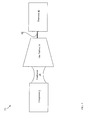
- FIG. 3 shows a schematic view of a gas turbine system 32 according to aspects of the invention.
- the gas turbine system 32 can include the compressor 2 and a gas turbine 34 (such as turbine 28 of FIG. 1 ) coupled to the compressor 2.
- the gas turbine 34 can include any conventional gas turbine 34 capable of converting the fluid motion of heated gas into rotational motion.
- the compressor 2 can compress a fluid such as air, which can be combined with fuel in a combustor 36 for burning, which thereby produces a heated gas that can perform mechanical work in the gas turbine 34 (e.g., by causing rotation of a shaft coupled to turbine blades).
- the gas turbine 34 can be connected (e.g., mechanically coupled) with a generator 40 (e.g., via conventional shaft 42), to form a gas turbine system capable of, e.g., generating electrical power. It is further understood that the gas turbine 34 and/or generator 40 could be coupled to a conventional steam turbine system to form a combined cycle power generation system.
Landscapes
- Engineering & Computer Science (AREA)
- Mechanical Engineering (AREA)
- General Engineering & Computer Science (AREA)
- Chemical & Material Sciences (AREA)
- Combustion & Propulsion (AREA)
- Physics & Mathematics (AREA)
- Thermal Sciences (AREA)
- Fluid Mechanics (AREA)
- Structures Of Non-Positive Displacement Pumps (AREA)
Applications Claiming Priority (1)
| Application Number | Priority Date | Filing Date | Title |
|---|---|---|---|
| US13/297,354 US9068507B2 (en) | 2011-11-16 | 2011-11-16 | Compressor having purge circuit and method of purging |
Publications (2)
| Publication Number | Publication Date |
|---|---|
| EP2594765A2 true EP2594765A2 (fr) | 2013-05-22 |
| EP2594765A3 EP2594765A3 (fr) | 2019-04-24 |
Family
ID=47227568
Family Applications (1)
| Application Number | Title | Priority Date | Filing Date |
|---|---|---|---|
| EP12192418.7A Withdrawn EP2594765A3 (fr) | 2011-11-16 | 2012-11-13 | Compresseur avec un circuit de refroidissement et procédé de refroidissement correspondant |
Country Status (3)
| Country | Link |
|---|---|
| US (1) | US9068507B2 (fr) |
| EP (1) | EP2594765A3 (fr) |
| CN (1) | CN103115002B (fr) |
Family Cites Families (12)
| Publication number | Priority date | Publication date | Assignee | Title |
|---|---|---|---|---|
| DE3606597C1 (de) * | 1986-02-28 | 1987-02-19 | Mtu Muenchen Gmbh | Schaufel- und Dichtspaltoptimierungseinrichtung fuer Verdichter von Gasturbinentriebwerken |
| DE3638961A1 (de) * | 1986-11-14 | 1988-05-26 | Mtu Muenchen Gmbh | Gasturbinentriebwerk mit einem hochdruckverdichter |
| US5271711A (en) | 1992-05-11 | 1993-12-21 | General Electric Company | Compressor bore cooling manifold |
| US6574965B1 (en) * | 1998-12-23 | 2003-06-10 | United Technologies Corporation | Rotor tip bleed in gas turbine engines |
| DE102004055439A1 (de) * | 2004-11-17 | 2006-05-24 | Rolls-Royce Deutschland Ltd & Co Kg | Strömungsarbeitsmaschine mit dynamischer Strömungsbeeinflussung |
| GB0603030D0 (en) * | 2006-02-15 | 2006-03-29 | Rolls Royce Plc | Gas turbine engine rotor ventilation arrangement |
| US8302405B2 (en) * | 2006-10-13 | 2012-11-06 | Rolls-Royce Power Engineering Plc | Dynamic control of a gas turbine engine compressor during rapid transients |
| US8257016B2 (en) * | 2008-01-23 | 2012-09-04 | Rolls-Royce Deutschland Ltd & Co Kg | Gas turbine with a compressor with self-healing abradable coating |
| DE102008011644A1 (de) * | 2008-02-28 | 2009-09-03 | Rolls-Royce Deutschland Ltd & Co Kg | Gehäusestrukturierung für Axialverdichter im Nabenbereich |
| DE102008019603A1 (de) * | 2008-04-18 | 2009-10-22 | Rolls-Royce Deutschland Ltd & Co Kg | Strömungsmaschine mit schaufelreiheninterner Fluid-Rückführung |
| DE102008031982A1 (de) * | 2008-07-07 | 2010-01-14 | Rolls-Royce Deutschland Ltd & Co Kg | Strömungsarbeitsmaschine mit Nut an einem Laufspalt eines Schaufelendes |
| US7993102B2 (en) | 2009-01-09 | 2011-08-09 | General Electric Company | Rotor cooling circuit |
-
2011
- 2011-11-16 US US13/297,354 patent/US9068507B2/en active Active
-
2012
- 2012-11-13 EP EP12192418.7A patent/EP2594765A3/fr not_active Withdrawn
- 2012-11-16 CN CN201210464584.9A patent/CN103115002B/zh active Active
Non-Patent Citations (1)
| Title |
|---|
| None |
Also Published As
| Publication number | Publication date |
|---|---|
| CN103115002B (zh) | 2017-06-27 |
| CN103115002A (zh) | 2013-05-22 |
| US9068507B2 (en) | 2015-06-30 |
| US20130121803A1 (en) | 2013-05-16 |
| EP2594765A3 (fr) | 2019-04-24 |
Similar Documents
| Publication | Publication Date | Title |
|---|---|---|
| US9797310B2 (en) | Heat pipe temperature management system for a turbomachine | |
| CN1280531C (zh) | 减少冷却空气流的压气机系统和方法 | |
| US11111858B2 (en) | Cool core gas turbine engine | |
| CN110284975B (zh) | 降低停机后发动机温度的系统和方法 | |
| JP5584410B2 (ja) | マルチソース型ガスタービン冷却 | |
| CN110185501B (zh) | 带具有冷却入口的导叶的燃气涡轮发动机 | |
| EP3176408A1 (fr) | Système et procédé de refroidissement intermédiaire pour un moteur à turbine à gaz | |
| US20180216575A1 (en) | Cool core gas turbine engine | |
| CN110017211B (zh) | 具有密封件的涡轮发动机 | |
| JP2017106441A (ja) | ガスタービンエンジンのためのヒートパイプをもつ閉ループ冷却方法およびシステム | |
| CN107023503B (zh) | 主动高压压缩机间隙控制 | |
| US20190078514A1 (en) | Gas turbine engine active clearance control system using inlet particle separator | |
| EP2653659A2 (fr) | Ensemble de refroidissement pour système de turbine à gaz | |
| US10018067B2 (en) | Suction-based active clearance control system | |
| EP3205831A1 (fr) | Turbine à gaz avec une jante d'étanchéité entre le rotor et le stator | |
| CN109563744B (zh) | 带有吸气面密封的涡轮发动机 | |
| CN106884685B (zh) | 涡轮发动机组件及其操作方法 | |
| JP2016194297A (ja) | タービンフレーム及びタービンフレームのための翼形部 | |
| EP2551458A2 (fr) | Système d'étanchéité et de refroidissement d'aube | |
| US20190360395A1 (en) | Turbine stator vane with multiple outer diameter pressure feeds | |
| EP3150797A1 (fr) | Système de refroidissement perfectionné pour moteur de turbine | |
| CN102996249B (zh) | 燃气轮机 | |
| US9068507B2 (en) | Compressor having purge circuit and method of purging | |
| CN116892450A (zh) | 用于燃气涡轮发动机的热管理系统 | |
| CN103470318B (zh) | 控制涡轮发动机压缩机温度的方法及涡轮发动机的压缩机 |
Legal Events
| Date | Code | Title | Description |
|---|---|---|---|
| PUAI | Public reference made under article 153(3) epc to a published international application that has entered the european phase |
Free format text: ORIGINAL CODE: 0009012 |
|
| AK | Designated contracting states |
Kind code of ref document: A2 Designated state(s): AL AT BE BG CH CY CZ DE DK EE ES FI FR GB GR HR HU IE IS IT LI LT LU LV MC MK MT NL NO PL PT RO RS SE SI SK SM TR |
|
| AX | Request for extension of the european patent |
Extension state: BA ME |
|
| PUAL | Search report despatched |
Free format text: ORIGINAL CODE: 0009013 |
|
| AK | Designated contracting states |
Kind code of ref document: A3 Designated state(s): AL AT BE BG CH CY CZ DE DK EE ES FI FR GB GR HR HU IE IS IT LI LT LU LV MC MK MT NL NO PL PT RO RS SE SI SK SM TR |
|
| AX | Request for extension of the european patent |
Extension state: BA ME |
|
| RIC1 | Information provided on ipc code assigned before grant |
Ipc: F02C 7/18 20060101ALI20190321BHEP Ipc: F02C 9/18 20060101ALI20190321BHEP Ipc: F02C 7/12 20060101ALI20190321BHEP Ipc: F02C 6/08 20060101AFI20190321BHEP Ipc: F01D 17/10 20060101ALI20190321BHEP Ipc: F04D 27/02 20060101ALI20190321BHEP |
|
| STAA | Information on the status of an ep patent application or granted ep patent |
Free format text: STATUS: THE APPLICATION HAS BEEN PUBLISHED |
|
| STAA | Information on the status of an ep patent application or granted ep patent |
Free format text: STATUS: THE APPLICATION IS DEEMED TO BE WITHDRAWN |
|
| 18D | Application deemed to be withdrawn |
Effective date: 20191025 |