EP2594880A2 - Kühlschrank - Google Patents
Kühlschrank Download PDFInfo
- Publication number
- EP2594880A2 EP2594880A2 EP12007659.1A EP12007659A EP2594880A2 EP 2594880 A2 EP2594880 A2 EP 2594880A2 EP 12007659 A EP12007659 A EP 12007659A EP 2594880 A2 EP2594880 A2 EP 2594880A2
- Authority
- EP
- European Patent Office
- Prior art keywords
- recess
- refrigerator
- light source
- inner case
- cover
- Prior art date
- Legal status (The legal status is an assumption and is not a legal conclusion. Google has not performed a legal analysis and makes no representation as to the accuracy of the status listed.)
- Granted
Links
Images


Classifications
-
- F—MECHANICAL ENGINEERING; LIGHTING; HEATING; WEAPONS; BLASTING
- F25—REFRIGERATION OR COOLING; COMBINED HEATING AND REFRIGERATION SYSTEMS; HEAT PUMP SYSTEMS; MANUFACTURE OR STORAGE OF ICE; LIQUEFACTION SOLIDIFICATION OF GASES
- F25D—REFRIGERATORS; COLD ROOMS; ICE-BOXES; COOLING OR FREEZING APPARATUS NOT OTHERWISE PROVIDED FOR
- F25D27/00—Lighting arrangements
Definitions
- This relates to a refrigerator, and more particularly, to a refrigerator efficiently using the space of a refrigerating compartment and/or freezing compartment.
- a refrigerator stores items in a frozen or refrigerated state by lowering an internal temperature of a compartment thereof through discharge of cold air generated by a refrigeration cycle including a compressor, a condenser, an expansion valve, and an evaporator.
- a refrigeration cycle including a compressor, a condenser, an expansion valve, and an evaporator.
- Such a refrigerator may include a freezing compartment for storing items in a frozen state, and a refrigerating compartment for storing items at low temperature.
- a Kimchi refrigerator may store items such as Kimchi or vegetables in a fresh state.
- a refrigerator may include a plurality of doors, at least one of the plurality of doors being connected to a refrigerator body by hinges to open or close a front side of the refrigerator body.
- the refrigerator may include a drawer type door mounted to a front wall of a drawer slidably installed in the refrigerator. Items of various sizes and shapes may be stored in the freezing and refrigerating compartments, which may include a plurality of racks to vertically partition the storage compartment to receive such items.
- a lighting device may be activated to improve visibility in the freezing compartment or refrigerating compartment. Heat generated by such a lighting device may increase an internal temperature of the refrigerator thus wasting energy.
- FIG. 1 is a front view of a refrigerator according to an exemplary embodiment as broadly described herein;
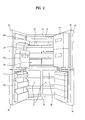
- FIG. 2 is a front view of the refrigerator shown in FIG. 1 with its doors open;
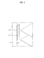
- FIG. 3 is a perspective view of a light source installed in a refrigerator, according to an embodiment as broadly described herein;
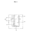
- FIG. 4 is an enlarged view of the light source shown in FIG. 3 ;
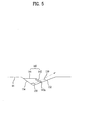
- FIG. 5 is a sectional view of the light source shown in FIG. 4 ;
- FIG. 6 is a perspective view of a light source installed in a refrigerator, according to another embodiment as broadly described herein.
- the refrigerator which is designated by reference numeral "10" is applicable not only to a top mount type refrigerator in which the inner space of the refrigerator is vertically partitioned to define a freezing compartment and a refrigerating compartment such that the freezing compartment is arranged above the refrigerating compartment, but also to a side-by-side type refrigerator in which the inner space of the refrigerator is laterally partitioned to define a freezing compartment and a refrigerating compartment such that the freezing compartment and refrigerating compartment are laterally arranged.
- exemplary embodiments will be described in conjunction with a bottom freezer type refrigerator. That is, the inner space of the exemplary refrigerator 10 is vertically partitioned by a barrier 16 to define a freezing compartment 32 positioned below the refrigerating compartment 22.
- the freezing compartment 32 may be maintained at a sub-zero temperature, and the refrigerating compartment 22 may be maintained at a temperature relatively higher than that of the freezing compartment 32.
- the refrigerator 10 may include a body which defines an outer appearance of the refrigerator 10 while also protecting mechanical devices received therein.
- the body of the refrigerator 10 may include an outer case 12 which defines an outer appearance of the refrigerator 10, and an inner case 14 which defines storage compartments therein, namely, the freezing compartment 32 and the refrigerating compartment 22.
- a certain space may be defined between the outer case 12 and the inner case 14.
- a passage for circulation of cold air may be formed in the space.
- a machinery chamber may be formed in the space between the outer case 12 and the inner case 14 to accommodate a refrigerant cycle device for generating cold air through circulation of a refrigerant.
- a refrigerant cycle device for generating cold air through circulation of a refrigerant.
- the refrigerant cycle device may include, for example, a compressor for compressing a refrigerant, and an evaporator for changing the phase of the refrigerant from liquid to gas, to cause the refrigerant to exchange heat with the outside of the refrigerant cycle device.
- the refrigerator 10 may include a freezing compartment door 30 for opening or closing the freezing compartment 32, and a refrigerating compartment door 20 for opening or closing the refrigerating compartment 22.
- Each of the freezing compartment door 30 and refrigerating compartment door 20 may be pivotally mounted to the body of the refrigerator 10 at one end thereof by hinges.
- Each of the freezing compartment door 30 and refrigerating compartment door 20 may include a plurality of doors. That is, as shown in FIG. 2 , each of the freezing compartment door 30 and refrigerating compartment door 20 may be configured such that it opens forward while being pivotally moved about opposite lateral edges of the refrigerator 10.
- the barrier 16 may be positioned horizontally between the freezing compartment 32 and the refrigerating compartment 22, to partition the freezing compartment 32 and refrigerating compartment 22.
- the barrier 16 may be formed at the inner case 14 such that it has a certain thickness.
- the barrier 16 may extend horizontally to vertically partition the freezing compartment 32 and refrigerating compartment 22 such that the freezing compartment 32 and refrigerating compartment 22 are disposed below and above the barrier 16, respectively.
- a partition wall 18 may be positioned in the freezing compartment 32, for example at a central portion thereof, to partition the freezing compartment 32 into two separate spaces.
- the partition wall 18 may be vertically installed at the inner case 14 such that the freezing compartment 32 is divided into two laterally arranged compartments.
- the freezing compartment door 30 may include two doors for opening or closing respective freezing compartments 32.
- FIGs. 1 and 2 there is no partition wall installed in the refrigerating compartment 22 to laterally partition the refrigerating compartment 22.
- a partition wall may be installed in the refrigerating compartment 22, as in the freezing compartment 32.
- Racks, drawers, baskets, and the like may be disposed in each of the freezing compartment 32 and refrigerating compartment 22, to store various items.
- a drawer 40 may be mounted in the freezing compartment and slidably extracted or retracted. Food and other such items may be stored in the drawer 40.
- a vertically-extending cover may be mounted to a front wall of the drawer 40 to preserve cold air in the freezing compartment 32 even when the freezing compartment door 30 is opened.
- a plurality of drawers 40 may be provided in the freezing compartment 32.
- the drawers 40 may be arranged at opposite sides of the partition wall 18, and stacked vertically.
- a light source 150 may be installed in the freezing compartment 32 and/or refrigerating compartment 22.
- the light source 150 may operate when the freezing compartment door 30 or refrigerating compartment door 20 is opened.
- the light source 150 may emit light toward the interior of the freezing compartment 32 and/or refrigerating compartment 22 to improve visibility therein.
- the refrigerator shown in FIGs. 1 and 2 may include a recess 130 formed in the inner case 14, the recess 130 having a predetermined depth, with the light source 150 received in the recess 130 and a cover 140 extending across the recess 130.
- the light source 150 may be a light emitting diode (LED).
- LED light emitting diode
- An LED is a semiconductor device in which light is emitted when current flows through a compound such as gallium arsenide.
- Such an LED may have a structure in which, when current passes through a conductive material layer between electrodes attached to upper and lower surfaces of the conductive material layer, electrons and holes called “positively-charged particles" are coupled between the electrodes, thereby emitting photons of light.
- light emitted from the conductive material may exhibit various colors such as, for example, yellow, green, blue, and white.
- a white LED will be applied to the light source as embodied and broadly described herein.
- Such an LED may efficiently and effectively convert electricity into light, when compared to other light emitting devices such as a tungsten bulb or a neon lamp. Since the LED may generate significantly less heat, and may be significantly smaller and lighter, the LED may provide a longer lifespan. In addition, the time taken from initiation of current flow to emission of light may be relatively short, thus providing improved response characteristics.
- LED light source 150 does not emit any appreciable amount of heat, especially when compared to other light sources, the temperature of the freezing compartment 32 and/or refrigerating compartment 22 is not affected, i.e., increased, due to heat generated by the light source 150, thus reducing energy required to drive a refrigeration cycle device and maintain a desired temperature in the compartments 32/22.
- the light source 150 may direct emitted light toward a rear portion of the inner case 14.
- the rear side of the inner case 14 corresponds to an interior of the refrigerator 10
- the front side of the inner case 14 corresponds to a user access side of the refrigerator 10.
- the following description will be provided on the assumption that the rear side of the inner case 14 corresponds to an inward direction of the freezing compartment 32 or refrigerating compartment 22, whereas the front side of the inner case 14 corresponds to an outward direction of the freezing compartment 32 or refrigerating compartment 22.
- the user To access the interior of the refrigerator, the user first opens the freezing compartment door 30 or the refrigerating compartment door 20, and may then access the freezing compartment 32 or refrigerating compartment 22. At this time, the user is positioned at the front side of the freezing compartment 32 or refrigerating compartment 22, and visually opposite to the irradiation direction of light emitted from the light source 150. Accordingly, light emitted from the light source 150 does not shine in the eyes of the user.
- an LED used in accordance with such an embodiment may emit light exhibiting relatively high linearity and relatively high intensity of illumination. For this reason, when light from the LED is directed toward the user, the user may become uncomfortable.
- the light source 150 may be installed such that light emitted by the light source 150 is directed to the rear side of the inner case 14. In particular, the light source 150 may be directed toward a rear wall of the inner case 14.
- the light source 150 may be received in the recess 130 such that it does not protrude outward from the inner case 14.
- a plurality of racks may be installed around a region where the light source 150 is installed.
- the racks may be installed in the refrigerating compartment 22 or freezing compartment 33 at various levels as appropriate.
- the light source 150 which may be disposed adjacent to the racks, may be installed such that it does not protrude outward from the inner case 14.
- the light source 150 may be installed at one or more lateral sides of the inner case 14, received in the recess 130, so that it does not interfere with extraction or retraction of the racks.
- the light source 150 may include a plurality of aligned LEDs.
- the recess 130 and light source 150 may be installed in a vertically elongated manner. Thus, it may be possible to uniformly irradiate light into the interior of the inner case 14. Since light emitted from an LED generally exhibits high linearity, as compared to other light sources, such a plurality of LEDs may be arranged at regular intervals in order to irradiate light throughout the interior of the refrigerating compartment 22 or the freezing compartment 32.
- FIG. 4 is an enlarged detail view of the light source installation shown in FIG. 3
- FIG. 5 is a sectional view of a portion of FIG. 4 .
- the recess 130 may include a first inclined surface 132 directed to the front side of the freezing compartment 32 or refrigerating compartment 22, and a second inclined surface 134 directed to the rear side of the freezing compartment 32 or refrigerating compartment 22.
- the first inclined surface 132 and second inclined surface 134 may be arranged such that they contact each other at confronting ends thereof in the form of a "V" shape while defining an obtuse angle therebetween.
- the first inclined surface 132 and second inclined surface 134 may be arranged such that they contact each other at confronting ends thereof while defining a right angle or an acute angle therebetween.
- the following description will be provided only in conjunction with arrangement shown in FIGs. 4 and 5 .
- first inclined surface 132 and second inclined surface 134 are directed to the front side and the rear side, respectively, of the freezing compartment 32 or refrigerating compartment 22, indicating that a normal direction of the first inclined surface 132 is directed to the front side and the normal direction of the second inclined surface 132 is directed to the rear side of the freezing compartment 32 or refrigerating compartment 22 as appropriate.
- the recess 130 may also include extension surfaces 136 each forming a side surface connecting the first and second inclined surfaces 132 and 134.
- Two extension surfaces 136 may be formed at opposite ends of the first inclined surface 132, respectively, to connect the first and second inclined surfaces 132 and 134.
- a shape of each extension surface 136 may be defined by the end edges of the first and second inclined surfaces 132 and 134.
- the extension surface 136 may have a substantially triangular shape.
- the extension surface 136 may be provided as a reflective member capable of reflecting light so as to enhance the efficiency of light emitted from the light source 150.
- the cover 140 may be provided in the recess 130 surrounding the light source 150 to seal the space where the light source 150 is installed, and to prevent the light source 150 from being directly exposed to the freezing compartment 32 or refrigerating compartment 22.
- heat generated by the light source 150 may be transmitted to the freezing compartment 32 or refrigerating compartment 22 through direct heat exchange, increasing the internal temperature of the freezing compartment 32 or refrigerating compartment 22.
- the cover 140 may have a predetermined thickness or greater.
- the cover 140 may include an inclined piece 142 directed to the rear side of the inner case 14 and contacting the first inclined surface 132. Since the inclined piece 142 is directed to the rear side of the inner case 14, light emitted by the light source 150 may be directed to the rear side of the inner case 14, namely, the inside of the freezing compartment 32 or refrigerating compartment 22, through the inclined piece 142.
- the inclined piece 142 may be made of a transparent material so that light emitted from the light source 150 may be directed to the rear side of the inner case 14 after passing through the inclined piece 142.
- Irregularities may be formed at the inclined piece 142 to scatter light emitted by the light source 150.
- Such irregularities may form a diffusion pattern 142a that may scatter the light from the light source 150 in various directions within a range in which the light is directed to the rear side of the inner case 14. Since the LED used as the light source 150 may exhibit high linearity, light emitted by the light source 150 may be directed only to the rear side of the inner case 14 unless the light is scatted by these irregularities forming such a diffusion pattern 142a. If not scattered in this manner, any regions to which light from the light source 150 is not directly irradiated may exhibit relatively low intensity of illumination.
- irregularities may be provided on the inclined piece 142 to scatter light emitted by the light source 150 such that it is irradiated to region(s) to which light would not otherwise be directly irradiated.
- the cover 140 may also include an extension piece 144 extending substantially in parallel to the inner case 14. In this case, it may be possible to prevent light emitted by the light source 150 from being irradiated toward the front side of the inner case 14 through the extension piece 144.
- the extension piece 144 may instead be installed such that it is inclined by a predetermined angle with regard to the surface of the inner case 14. If the extension piece 144 is inclined by such a predetermined angle, the extension piece 144 may still be directed to the rear side of the inner case 14. If the extension piece 144 were directed to the front side of the inner case 14, light emitted by the light source 150 would be irradiated toward the front side of the inner case 14, directing the light at the user and causing discomfort.
- the extension piece 144 may be made of a semi-transparent material, to avoid light passing through the extension piece 144 from being directly irradiated at the user. However, in most embodiments, the extension piece 144 is not made of a non-transmissive material through which light cannot pass at all, as this would cause some degradation of energy efficiency, as some portion of the light emitted by the light source 150 would not be used.
- the recess 130 and light source 150 are installed at a top of the inner case 14, rather than in a lateral side of the inner case 14. That is, the recess 130 and light source 150 may be installed at any one of the top side and/or the lateral sides of the freezing compartment 32 and/or refrigerating compartment 22.
- the light source 150 may be directed toward the rear side of the inner case 14.
- the light source 150 is installed in the refrigerating compartment 22 in the embodiment shown in FIG. 2 , it may also be installed in the freezing compartment 32 in the same manner.
- enhancement in energy efficiency may be achieved, as energy required to drive the light source may be reduced.
- an amount of heat generated during driving of the light source may be reduced when using an LED as the light source. Accordingly, the energy required to drive a refrigeration cycle in order to again lower the temperature, which may have been increased by the heat generated by the light source, may be saved.
- a refrigerator is provided that is capable of reducing heat generated by a light source, thereby achieving an enhancement in energy efficiency during operation of the refrigerator.
- a refrigerator is provided that is capable of preventing light emitted from a light source from being directed at a user, thereby avoiding discomfort due to the light.
- a refrigerator as embodied and broadly described herein may include an inner case for defining a freezing compartment and/or a refrigerating compartment therein, a recess formed at the inner case to have a predetermined depth, a light source received in the recess, and a cover received in the recess while surrounding the light source, wherein the light source irradiates light toward a rear side of the inner case, wherein the cover comprises an extension piece substantially extending in parallel to the inner case while being received in the recess.
- the recess may include a first inclined surface directed to a front side of the freezing compartment or a front side of the refrigerating compartment, and a second inclined surface directed to a rear side of the freezing compartment or a rear side of the refrigerating compartment.
- the cover may also include an inclined piece directed to the rear side of the inner case.
- the inclined piece may be disposed adjacent to the first inclined surface.
- the inclined piece may be formed with irregularities for scattering light emitted from the light source.
- the inclined piece may be made of a transparent material.
- the extension piece may be made of a semi-transparent material.
- the extension piece may have a predetermined inclination such that the extension piece is directed to the rear side of the inner case.
- the light source may be received in the recess such that the light source is not protruded outwardly of the inner case.
- the recess may include extension surfaces each forming a side surface connecting the first inclined surface and the second inclined surface.
- the light source may include a light emitting diode (LED).
- LED light emitting diode
- any reference in this specification to "one embodiment,” “an embodiment,” “example embodiment,” etc. means that a particular feature, structure, or characteristic described in connection with the embodiment is included in at least one embodiment of the invention.
- the appearances of such phrases in various places in the specification are not necessarily all referring to the same embodiment.
Landscapes
- Engineering & Computer Science (AREA)
- Chemical & Material Sciences (AREA)
- Combustion & Propulsion (AREA)
- Physics & Mathematics (AREA)
- Mechanical Engineering (AREA)
- Thermal Sciences (AREA)
- General Engineering & Computer Science (AREA)
- Devices That Are Associated With Refrigeration Equipment (AREA)
- Cold Air Circulating Systems And Constructional Details In Refrigerators (AREA)
Applications Claiming Priority (1)
| Application Number | Priority Date | Filing Date | Title |
|---|---|---|---|
| KR1020110120776A KR20130055176A (ko) | 2011-11-18 | 2011-11-18 | 냉장고 |
Publications (3)
| Publication Number | Publication Date |
|---|---|
| EP2594880A2 true EP2594880A2 (de) | 2013-05-22 |
| EP2594880A3 EP2594880A3 (de) | 2017-01-18 |
| EP2594880B1 EP2594880B1 (de) | 2020-10-28 |
Family
ID=47221078
Family Applications (1)
| Application Number | Title | Priority Date | Filing Date |
|---|---|---|---|
| EP12007659.1A Active EP2594880B1 (de) | 2011-11-18 | 2012-11-12 | Kühlschrank |
Country Status (4)
| Country | Link |
|---|---|
| US (1) | US20130128494A1 (de) |
| EP (1) | EP2594880B1 (de) |
| KR (1) | KR20130055176A (de) |
| CN (1) | CN103123201A (de) |
Cited By (7)
| Publication number | Priority date | Publication date | Assignee | Title |
|---|---|---|---|---|
| DE202020101477U1 (de) | 2020-03-18 | 2020-03-26 | BSH Hausgeräte GmbH | Haushaltsgerät mit Leuchte für Behandlungsraum |
| EP3882545A1 (de) | 2020-03-18 | 2021-09-22 | BSH Hausgeräte GmbH | Haushaltsgerät mit leuchte für behandlungsraum |
| DE102020203444A1 (de) | 2020-03-18 | 2021-09-23 | BSH Hausgeräte GmbH | Haushaltsgerät mit Leuchte für Behandlungsraum |
| EP4119876A1 (de) * | 2021-07-16 | 2023-01-18 | BSH Hausgeräte GmbH | Haushaltskältegerät mit einem innenbehälter und einem daran angeordneten lichtquellenmodul, welches eine spezifische lichtaustrittskante aufweist |
| DE102022210383A1 (de) | 2022-09-30 | 2024-04-04 | BSH Hausgeräte GmbH | Haushaltsgerät, Verfahren zum Montieren eines Haushaltsgeräts, Leuchte für ein Haushaltsgerät sowie Verfahren zum Zusammenbau einer Leuchte |
| WO2025201883A1 (de) | 2024-03-25 | 2025-10-02 | BSH Hausgeräte GmbH | Haushaltsgerät und leuchte für ein haushaltsgerät |
| WO2025201882A1 (de) | 2024-03-25 | 2025-10-02 | BSH Hausgeräte GmbH | Haushaltsgerät und leuchte für ein haushaltsgerät |
Families Citing this family (6)
| Publication number | Priority date | Publication date | Assignee | Title |
|---|---|---|---|---|
| BR102014013430A2 (pt) * | 2014-06-03 | 2015-12-29 | Whirlpool Sa | sistema de iluminação integrado para aparelhos eletrodomésticos, e aparelho eletrodoméstico provido do referido sistema de iluminação |
| US9631861B1 (en) * | 2014-12-23 | 2017-04-25 | Bsh Hausgeraete Gmbh | Home appliance comprising an illumination element |
| DE102015203186A1 (de) * | 2015-02-23 | 2016-08-25 | BSH Hausgeräte GmbH | Kältegerät mit einer Tür |
| JP6584670B2 (ja) * | 2016-07-15 | 2019-10-02 | 三菱電機株式会社 | 冷蔵庫 |
| KR102624852B1 (ko) | 2018-12-11 | 2024-01-15 | 삼성전자주식회사 | 냉장고 |
| CN210625106U (zh) * | 2019-05-16 | 2020-05-26 | 青岛海尔电冰箱有限公司 | 冰箱 |
Family Cites Families (10)
| Publication number | Priority date | Publication date | Assignee | Title |
|---|---|---|---|---|
| US2995649A (en) * | 1958-03-26 | 1961-08-08 | Westinghouse Electric Corp | Refrigeration apparatus |
| JP2006253048A (ja) * | 2005-03-14 | 2006-09-21 | Osram-Melco Ltd | 反射鏡付放電ランプ |
| JP4481283B2 (ja) * | 2006-09-15 | 2010-06-16 | パナソニック株式会社 | 冷蔵庫 |
| JP5197172B2 (ja) * | 2008-06-12 | 2013-05-15 | 三菱電機株式会社 | 冷蔵庫 |
| JP5197185B2 (ja) * | 2008-06-30 | 2013-05-15 | 三菱電機株式会社 | 冷蔵庫 |
| DE102008044302A1 (de) * | 2008-12-03 | 2010-06-10 | BSH Bosch und Siemens Hausgeräte GmbH | Kältegerätekorpus mit Innenbeleuchtung |
| JP2011196674A (ja) * | 2010-02-26 | 2011-10-06 | Panasonic Corp | 冷蔵庫 |
| JP5620695B2 (ja) * | 2010-03-03 | 2014-11-05 | パナソニック株式会社 | 冷蔵庫 |
| JP2011179797A (ja) * | 2010-03-03 | 2011-09-15 | Panasonic Corp | 冷蔵庫 |
| CN102753922B (zh) * | 2010-03-03 | 2015-05-13 | 松下电器产业株式会社 | 冷藏库 |
-
2011
- 2011-11-18 KR KR1020110120776A patent/KR20130055176A/ko not_active Ceased
-
2012
- 2012-11-01 US US13/666,067 patent/US20130128494A1/en not_active Abandoned
- 2012-11-07 CN CN2012104413042A patent/CN103123201A/zh active Pending
- 2012-11-12 EP EP12007659.1A patent/EP2594880B1/de active Active
Non-Patent Citations (1)
| Title |
|---|
| None |
Cited By (9)
| Publication number | Priority date | Publication date | Assignee | Title |
|---|---|---|---|---|
| DE202020101477U1 (de) | 2020-03-18 | 2020-03-26 | BSH Hausgeräte GmbH | Haushaltsgerät mit Leuchte für Behandlungsraum |
| EP3882545A1 (de) | 2020-03-18 | 2021-09-22 | BSH Hausgeräte GmbH | Haushaltsgerät mit leuchte für behandlungsraum |
| DE102020203444A1 (de) | 2020-03-18 | 2021-09-23 | BSH Hausgeräte GmbH | Haushaltsgerät mit Leuchte für Behandlungsraum |
| CN113432376A (zh) * | 2020-03-18 | 2021-09-24 | Bsh家用电器有限公司 | 具有用于处理空间的发光体的家用器具 |
| CN113432376B (zh) * | 2020-03-18 | 2023-01-03 | Bsh家用电器有限公司 | 具有用于处理空间的发光体的家用器具 |
| EP4119876A1 (de) * | 2021-07-16 | 2023-01-18 | BSH Hausgeräte GmbH | Haushaltskältegerät mit einem innenbehälter und einem daran angeordneten lichtquellenmodul, welches eine spezifische lichtaustrittskante aufweist |
| DE102022210383A1 (de) | 2022-09-30 | 2024-04-04 | BSH Hausgeräte GmbH | Haushaltsgerät, Verfahren zum Montieren eines Haushaltsgeräts, Leuchte für ein Haushaltsgerät sowie Verfahren zum Zusammenbau einer Leuchte |
| WO2025201883A1 (de) | 2024-03-25 | 2025-10-02 | BSH Hausgeräte GmbH | Haushaltsgerät und leuchte für ein haushaltsgerät |
| WO2025201882A1 (de) | 2024-03-25 | 2025-10-02 | BSH Hausgeräte GmbH | Haushaltsgerät und leuchte für ein haushaltsgerät |
Also Published As
| Publication number | Publication date |
|---|---|
| EP2594880B1 (de) | 2020-10-28 |
| US20130128494A1 (en) | 2013-05-23 |
| EP2594880A3 (de) | 2017-01-18 |
| CN103123201A (zh) | 2013-05-29 |
| KR20130055176A (ko) | 2013-05-28 |
Similar Documents
| Publication | Publication Date | Title |
|---|---|---|
| EP2594880B1 (de) | Kühlschrank | |
| ES2355174T3 (es) | Refrigerador. | |
| CN100533022C (zh) | 冰箱 | |
| KR101331949B1 (ko) | 조명장치를 구비한 냉장고 | |
| JP5674496B2 (ja) | 冷蔵庫 | |
| CN101968297B (zh) | 冰箱 | |
| JP4811210B2 (ja) | 冷蔵庫 | |
| KR101110507B1 (ko) | 냉장고 및 냉장고 내부 조명장치 | |
| JP4409414B2 (ja) | 冷蔵庫 | |
| JP5344793B2 (ja) | 冷蔵庫 | |
| JP6584670B2 (ja) | 冷蔵庫 | |
| JPWO2019163126A1 (ja) | 冷蔵庫 | |
| KR102583888B1 (ko) | 냉장고 | |
| JP2012220134A (ja) | 冷蔵庫 | |
| KR20090132400A (ko) | 냉장고의 조명장치 | |
| JP4983900B2 (ja) | 冷蔵庫 | |
| US11454388B2 (en) | Refrigerator | |
| KR20070049359A (ko) | 냉장고 | |
| JP2012026678A (ja) | 冷蔵庫 | |
| CN101317066A (zh) | 冰箱 | |
| JP2008039355A (ja) | 冷蔵庫 | |
| CN219797598U (zh) | 冰箱 | |
| KR102214066B1 (ko) | 냉장고 | |
| KR20070058803A (ko) | 야광 냉장고 | |
| TWI676775B (zh) | 電冰箱 |
Legal Events
| Date | Code | Title | Description |
|---|---|---|---|
| PUAI | Public reference made under article 153(3) epc to a published international application that has entered the european phase |
Free format text: ORIGINAL CODE: 0009012 |
|
| AK | Designated contracting states |
Kind code of ref document: A2 Designated state(s): AL AT BE BG CH CY CZ DE DK EE ES FI FR GB GR HR HU IE IS IT LI LT LU LV MC MK MT NL NO PL PT RO RS SE SI SK SM TR |
|
| AX | Request for extension of the european patent |
Extension state: BA ME |
|
| 17P | Request for examination filed |
Effective date: 20140331 |
|
| RBV | Designated contracting states (corrected) |
Designated state(s): AL AT BE BG CH CY CZ DE DK EE ES FI FR GB GR HR HU IE IS IT LI LT LU LV MC MK MT NL NO PL PT RO RS SE SI SK SM TR |
|
| PUAL | Search report despatched |
Free format text: ORIGINAL CODE: 0009013 |
|
| AK | Designated contracting states |
Kind code of ref document: A3 Designated state(s): AL AT BE BG CH CY CZ DE DK EE ES FI FR GB GR HR HU IE IS IT LI LT LU LV MC MK MT NL NO PL PT RO RS SE SI SK SM TR |
|
| AX | Request for extension of the european patent |
Extension state: BA ME |
|
| RIC1 | Information provided on ipc code assigned before grant |
Ipc: F25D 27/00 20060101AFI20161214BHEP |
|
| GRAP | Despatch of communication of intention to grant a patent |
Free format text: ORIGINAL CODE: EPIDOSNIGR1 |
|
| STAA | Information on the status of an ep patent application or granted ep patent |
Free format text: STATUS: GRANT OF PATENT IS INTENDED |
|
| INTG | Intention to grant announced |
Effective date: 20200527 |
|
| RAP1 | Party data changed (applicant data changed or rights of an application transferred) |
Owner name: LG ELECTRONICS INC. |
|
| GRAS | Grant fee paid |
Free format text: ORIGINAL CODE: EPIDOSNIGR3 |
|
| GRAA | (expected) grant |
Free format text: ORIGINAL CODE: 0009210 |
|
| STAA | Information on the status of an ep patent application or granted ep patent |
Free format text: STATUS: THE PATENT HAS BEEN GRANTED |
|
| AK | Designated contracting states |
Kind code of ref document: B1 Designated state(s): AL AT BE BG CH CY CZ DE DK EE ES FI FR GB GR HR HU IE IS IT LI LT LU LV MC MK MT NL NO PL PT RO RS SE SI SK SM TR |
|
| REG | Reference to a national code |
Ref country code: GB Ref legal event code: FG4D |
|
| REG | Reference to a national code |
Ref country code: CH Ref legal event code: EP |
|
| REG | Reference to a national code |
Ref country code: DE Ref legal event code: R096 Ref document number: 602012072956 Country of ref document: DE |
|
| REG | Reference to a national code |
Ref country code: AT Ref legal event code: REF Ref document number: 1328629 Country of ref document: AT Kind code of ref document: T Effective date: 20201115 |
|
| REG | Reference to a national code |
Ref country code: IE Ref legal event code: FG4D |
|
| REG | Reference to a national code |
Ref country code: AT Ref legal event code: MK05 Ref document number: 1328629 Country of ref document: AT Kind code of ref document: T Effective date: 20201028 |
|
| REG | Reference to a national code |
Ref country code: NL Ref legal event code: MP Effective date: 20201028 |
|
| PG25 | Lapsed in a contracting state [announced via postgrant information from national office to epo] |
Ref country code: PT Free format text: LAPSE BECAUSE OF FAILURE TO SUBMIT A TRANSLATION OF THE DESCRIPTION OR TO PAY THE FEE WITHIN THE PRESCRIBED TIME-LIMIT Effective date: 20210301 Ref country code: NO Free format text: LAPSE BECAUSE OF FAILURE TO SUBMIT A TRANSLATION OF THE DESCRIPTION OR TO PAY THE FEE WITHIN THE PRESCRIBED TIME-LIMIT Effective date: 20210128 Ref country code: NL Free format text: LAPSE BECAUSE OF FAILURE TO SUBMIT A TRANSLATION OF THE DESCRIPTION OR TO PAY THE FEE WITHIN THE PRESCRIBED TIME-LIMIT Effective date: 20201028 Ref country code: FI Free format text: LAPSE BECAUSE OF FAILURE TO SUBMIT A TRANSLATION OF THE DESCRIPTION OR TO PAY THE FEE WITHIN THE PRESCRIBED TIME-LIMIT Effective date: 20201028 Ref country code: RS Free format text: LAPSE BECAUSE OF FAILURE TO SUBMIT A TRANSLATION OF THE DESCRIPTION OR TO PAY THE FEE WITHIN THE PRESCRIBED TIME-LIMIT Effective date: 20201028 Ref country code: GR Free format text: LAPSE BECAUSE OF FAILURE TO SUBMIT A TRANSLATION OF THE DESCRIPTION OR TO PAY THE FEE WITHIN THE PRESCRIBED TIME-LIMIT Effective date: 20210129 |
|
| REG | Reference to a national code |
Ref country code: LT Ref legal event code: MG4D |
|
| PG25 | Lapsed in a contracting state [announced via postgrant information from national office to epo] |
Ref country code: LV Free format text: LAPSE BECAUSE OF FAILURE TO SUBMIT A TRANSLATION OF THE DESCRIPTION OR TO PAY THE FEE WITHIN THE PRESCRIBED TIME-LIMIT Effective date: 20201028 Ref country code: PL Free format text: LAPSE BECAUSE OF FAILURE TO SUBMIT A TRANSLATION OF THE DESCRIPTION OR TO PAY THE FEE WITHIN THE PRESCRIBED TIME-LIMIT Effective date: 20201028 Ref country code: SE Free format text: LAPSE BECAUSE OF FAILURE TO SUBMIT A TRANSLATION OF THE DESCRIPTION OR TO PAY THE FEE WITHIN THE PRESCRIBED TIME-LIMIT Effective date: 20201028 Ref country code: IS Free format text: LAPSE BECAUSE OF FAILURE TO SUBMIT A TRANSLATION OF THE DESCRIPTION OR TO PAY THE FEE WITHIN THE PRESCRIBED TIME-LIMIT Effective date: 20210228 Ref country code: ES Free format text: LAPSE BECAUSE OF FAILURE TO SUBMIT A TRANSLATION OF THE DESCRIPTION OR TO PAY THE FEE WITHIN THE PRESCRIBED TIME-LIMIT Effective date: 20201028 Ref country code: AT Free format text: LAPSE BECAUSE OF FAILURE TO SUBMIT A TRANSLATION OF THE DESCRIPTION OR TO PAY THE FEE WITHIN THE PRESCRIBED TIME-LIMIT Effective date: 20201028 Ref country code: BG Free format text: LAPSE BECAUSE OF FAILURE TO SUBMIT A TRANSLATION OF THE DESCRIPTION OR TO PAY THE FEE WITHIN THE PRESCRIBED TIME-LIMIT Effective date: 20210128 |
|
| PG25 | Lapsed in a contracting state [announced via postgrant information from national office to epo] |
Ref country code: HR Free format text: LAPSE BECAUSE OF FAILURE TO SUBMIT A TRANSLATION OF THE DESCRIPTION OR TO PAY THE FEE WITHIN THE PRESCRIBED TIME-LIMIT Effective date: 20201028 |
|
| REG | Reference to a national code |
Ref country code: CH Ref legal event code: PL |
|
| REG | Reference to a national code |
Ref country code: DE Ref legal event code: R097 Ref document number: 602012072956 Country of ref document: DE |
|
| PG25 | Lapsed in a contracting state [announced via postgrant information from national office to epo] |
Ref country code: RO Free format text: LAPSE BECAUSE OF FAILURE TO SUBMIT A TRANSLATION OF THE DESCRIPTION OR TO PAY THE FEE WITHIN THE PRESCRIBED TIME-LIMIT Effective date: 20201028 Ref country code: SK Free format text: LAPSE BECAUSE OF FAILURE TO SUBMIT A TRANSLATION OF THE DESCRIPTION OR TO PAY THE FEE WITHIN THE PRESCRIBED TIME-LIMIT Effective date: 20201028 Ref country code: LT Free format text: LAPSE BECAUSE OF FAILURE TO SUBMIT A TRANSLATION OF THE DESCRIPTION OR TO PAY THE FEE WITHIN THE PRESCRIBED TIME-LIMIT Effective date: 20201028 Ref country code: MC Free format text: LAPSE BECAUSE OF FAILURE TO SUBMIT A TRANSLATION OF THE DESCRIPTION OR TO PAY THE FEE WITHIN THE PRESCRIBED TIME-LIMIT Effective date: 20201028 Ref country code: LU Free format text: LAPSE BECAUSE OF NON-PAYMENT OF DUE FEES Effective date: 20201112 Ref country code: SM Free format text: LAPSE BECAUSE OF FAILURE TO SUBMIT A TRANSLATION OF THE DESCRIPTION OR TO PAY THE FEE WITHIN THE PRESCRIBED TIME-LIMIT Effective date: 20201028 Ref country code: EE Free format text: LAPSE BECAUSE OF FAILURE TO SUBMIT A TRANSLATION OF THE DESCRIPTION OR TO PAY THE FEE WITHIN THE PRESCRIBED TIME-LIMIT Effective date: 20201028 Ref country code: CZ Free format text: LAPSE BECAUSE OF FAILURE TO SUBMIT A TRANSLATION OF THE DESCRIPTION OR TO PAY THE FEE WITHIN THE PRESCRIBED TIME-LIMIT Effective date: 20201028 |
|
| REG | Reference to a national code |
Ref country code: BE Ref legal event code: MM Effective date: 20201130 |
|
| PG25 | Lapsed in a contracting state [announced via postgrant information from national office to epo] |
Ref country code: LI Free format text: LAPSE BECAUSE OF NON-PAYMENT OF DUE FEES Effective date: 20201130 Ref country code: CH Free format text: LAPSE BECAUSE OF NON-PAYMENT OF DUE FEES Effective date: 20201130 Ref country code: DK Free format text: LAPSE BECAUSE OF FAILURE TO SUBMIT A TRANSLATION OF THE DESCRIPTION OR TO PAY THE FEE WITHIN THE PRESCRIBED TIME-LIMIT Effective date: 20201028 |
|
| PLBE | No opposition filed within time limit |
Free format text: ORIGINAL CODE: 0009261 |
|
| STAA | Information on the status of an ep patent application or granted ep patent |
Free format text: STATUS: NO OPPOSITION FILED WITHIN TIME LIMIT |
|
| GBPC | Gb: european patent ceased through non-payment of renewal fee |
Effective date: 20210128 |
|
| 26N | No opposition filed |
Effective date: 20210729 |
|
| PG25 | Lapsed in a contracting state [announced via postgrant information from national office to epo] |
Ref country code: AL Free format text: LAPSE BECAUSE OF FAILURE TO SUBMIT A TRANSLATION OF THE DESCRIPTION OR TO PAY THE FEE WITHIN THE PRESCRIBED TIME-LIMIT Effective date: 20201028 Ref country code: IT Free format text: LAPSE BECAUSE OF FAILURE TO SUBMIT A TRANSLATION OF THE DESCRIPTION OR TO PAY THE FEE WITHIN THE PRESCRIBED TIME-LIMIT Effective date: 20201028 Ref country code: IE Free format text: LAPSE BECAUSE OF NON-PAYMENT OF DUE FEES Effective date: 20201112 Ref country code: FR Free format text: LAPSE BECAUSE OF NON-PAYMENT OF DUE FEES Effective date: 20201228 |
|
| PG25 | Lapsed in a contracting state [announced via postgrant information from national office to epo] |
Ref country code: SI Free format text: LAPSE BECAUSE OF FAILURE TO SUBMIT A TRANSLATION OF THE DESCRIPTION OR TO PAY THE FEE WITHIN THE PRESCRIBED TIME-LIMIT Effective date: 20201028 Ref country code: GB Free format text: LAPSE BECAUSE OF NON-PAYMENT OF DUE FEES Effective date: 20210128 |
|
| PG25 | Lapsed in a contracting state [announced via postgrant information from national office to epo] |
Ref country code: IS Free format text: LAPSE BECAUSE OF FAILURE TO SUBMIT A TRANSLATION OF THE DESCRIPTION OR TO PAY THE FEE WITHIN THE PRESCRIBED TIME-LIMIT Effective date: 20210228 Ref country code: TR Free format text: LAPSE BECAUSE OF FAILURE TO SUBMIT A TRANSLATION OF THE DESCRIPTION OR TO PAY THE FEE WITHIN THE PRESCRIBED TIME-LIMIT Effective date: 20201028 Ref country code: MT Free format text: LAPSE BECAUSE OF FAILURE TO SUBMIT A TRANSLATION OF THE DESCRIPTION OR TO PAY THE FEE WITHIN THE PRESCRIBED TIME-LIMIT Effective date: 20201028 Ref country code: CY Free format text: LAPSE BECAUSE OF FAILURE TO SUBMIT A TRANSLATION OF THE DESCRIPTION OR TO PAY THE FEE WITHIN THE PRESCRIBED TIME-LIMIT Effective date: 20201028 |
|
| PG25 | Lapsed in a contracting state [announced via postgrant information from national office to epo] |
Ref country code: MK Free format text: LAPSE BECAUSE OF FAILURE TO SUBMIT A TRANSLATION OF THE DESCRIPTION OR TO PAY THE FEE WITHIN THE PRESCRIBED TIME-LIMIT Effective date: 20201028 |
|
| PG25 | Lapsed in a contracting state [announced via postgrant information from national office to epo] |
Ref country code: BE Free format text: LAPSE BECAUSE OF NON-PAYMENT OF DUE FEES Effective date: 20201130 |
|
| PGFP | Annual fee paid to national office [announced via postgrant information from national office to epo] |
Ref country code: DE Payment date: 20251002 Year of fee payment: 14 |