EP2595019B1 - Verfahren und Vorrichtung zur Steuerung von analogem Ausgangsstrom - Google Patents
Verfahren und Vorrichtung zur Steuerung von analogem Ausgangsstrom Download PDFInfo
- Publication number
- EP2595019B1 EP2595019B1 EP12153386.3A EP12153386A EP2595019B1 EP 2595019 B1 EP2595019 B1 EP 2595019B1 EP 12153386 A EP12153386 A EP 12153386A EP 2595019 B1 EP2595019 B1 EP 2595019B1
- Authority
- EP
- European Patent Office
- Prior art keywords
- current
- driven
- driven current
- management unit
- pair
- Prior art date
- Legal status (The legal status is an assumption and is not a legal conclusion. Google has not performed a legal analysis and makes no representation as to the accuracy of the status listed.)
- Active
Links
Images



Classifications
-
- G—PHYSICS
- G05—CONTROLLING; REGULATING
- G05B—CONTROL OR REGULATING SYSTEMS IN GENERAL; FUNCTIONAL ELEMENTS OF SUCH SYSTEMS; MONITORING OR TESTING ARRANGEMENTS FOR SUCH SYSTEMS OR ELEMENTS
- G05B19/00—Program-control systems
- G05B19/02—Program-control systems electric
-
- G—PHYSICS
- G05—CONTROLLING; REGULATING
- G05B—CONTROL OR REGULATING SYSTEMS IN GENERAL; FUNCTIONAL ELEMENTS OF SUCH SYSTEMS; MONITORING OR TESTING ARRANGEMENTS FOR SUCH SYSTEMS OR ELEMENTS
- G05B19/00—Program-control systems
- G05B19/02—Program-control systems electric
- G05B19/04—Program control other than numerical control, i.e. in sequence controllers or logic controllers
- G05B19/042—Program control other than numerical control, i.e. in sequence controllers or logic controllers using digital processors
- G05B19/0423—Input/output
- G05B19/0425—Safety, monitoring
-
- G—PHYSICS
- G05—CONTROLLING; REGULATING
- G05B—CONTROL OR REGULATING SYSTEMS IN GENERAL; FUNCTIONAL ELEMENTS OF SUCH SYSTEMS; MONITORING OR TESTING ARRANGEMENTS FOR SUCH SYSTEMS OR ELEMENTS
- G05B9/00—Safety arrangements
- G05B9/02—Safety arrangements electric
- G05B9/03—Safety arrangements electric with multiple-channel loop, i.e. redundant control systems
-
- G—PHYSICS
- G05—CONTROLLING; REGULATING
- G05B—CONTROL OR REGULATING SYSTEMS IN GENERAL; FUNCTIONAL ELEMENTS OF SUCH SYSTEMS; MONITORING OR TESTING ARRANGEMENTS FOR SUCH SYSTEMS OR ELEMENTS
- G05B2219/00—Program-control systems
- G05B2219/20—Pc systems
- G05B2219/24—Pc safety
- G05B2219/24163—Authentication tag in configuration file
-
- G—PHYSICS
- G05—CONTROLLING; REGULATING
- G05B—CONTROL OR REGULATING SYSTEMS IN GENERAL; FUNCTIONAL ELEMENTS OF SUCH SYSTEMS; MONITORING OR TESTING ARRANGEMENTS FOR SUCH SYSTEMS OR ELEMENTS
- G05B2219/00—Program-control systems
- G05B2219/20—Pc systems
- G05B2219/24—Pc safety
- G05B2219/24182—Redundancy
-
- G—PHYSICS
- G05—CONTROLLING; REGULATING
- G05B—CONTROL OR REGULATING SYSTEMS IN GENERAL; FUNCTIONAL ELEMENTS OF SUCH SYSTEMS; MONITORING OR TESTING ARRANGEMENTS FOR SUCH SYSTEMS OR ELEMENTS
- G05B2219/00—Program-control systems
- G05B2219/20—Pc systems
- G05B2219/24—Pc safety
- G05B2219/24187—Redundant processors run identical programs
-
- G—PHYSICS
- G05—CONTROLLING; REGULATING
- G05B—CONTROL OR REGULATING SYSTEMS IN GENERAL; FUNCTIONAL ELEMENTS OF SUCH SYSTEMS; MONITORING OR TESTING ARRANGEMENTS FOR SUCH SYSTEMS OR ELEMENTS
- G05B2219/00—Program-control systems
- G05B2219/20—Pc systems
- G05B2219/24—Pc safety
- G05B2219/24189—Redundant processors monitor same point, common parameters
Definitions
- This invention relates to an apparatus and method for output current control in an Industrial Process Control System, in particular for an Industrial Process Control System suitable for:
- control systems are applicable to many industries including oil and gas production and refining, chemical production and processing, power generation, paper and textile mills and sewage treatment plants.
- fault tolerance is of utmost importance. Fault tolerance is the ability to continue functioning safely in the event of one or more failures within the system.
- Safety Integrity Level is defined as a relative level of risk-reduction provided by a safety function, or to specify a target level of risk reduction. In simple terms, SIL is a measurement of performance required for a Safety Instrumented Function.
- SIL 4 being the most dependable and SIL 1 being the least.
- a SIL is determined based on a number of quantitative factors in combination with qualitative factors such as development process and safety life cycle management.
- Fault tolerant systems are expensive to implement, and it is desirable to utilise an architecture which provides flexibility so that differing levels of fault tolerance can be provided depending upon the specified SIL.
- Fault tolerance may be achieved by a number of different techniques, each with specific advantages and disadvantages
- fault tolerance may be achieved is by providing 'redundancy'.
- Critical circuits are replicated and perform identical functions simultaneously and independently. The data outputs from replicated circuits are compared, and action taken depending upon the results. For example in a triplicated system a two out of three voting system may be implemented where if any two of the outputs agree then those values are assumed to be correct.
- Such solutions whilst effective, are complex and costly to implement.
- Another approach to fault tolerance is the use of hot-standby modules. This approach provides a level of fault tolerance whereby a standby module maintains system operation in the event of module failure. With this approach there may be some disruption to system operation during the changeover period.
- Fault tolerant systems ideally create a Fault Containment Region (FCR) to ensure that a fault within the FCR boundary does not propagate to the remainder of the system. This enables multiple faults to co-exist on different parts of a system without affecting operation.
- FCR Fault Containment Region
- Fault tolerant systems may also employ dedicated hardware and software test and diagnostic regimes that provide very fast fault recognition and response times to provide a safer system.
- Safety control systems are generally designed to be 'fail-operational/fail-safe'. Fail operational means that when a failure occurs, the system continues to operate: it is in a fail-operational state. The system will continue to operate in this state until the failed module is replaced and the system is returned to a fully operational state.
- a fault must be accurately detected, the faulty module needs to be isolated quickly, and the standby module needs to be deployed quickly. Furthermore, it is necessary to have a system which ensures that the standby module is in working correctly itself order to take control.
- This invention provides an improved output module providing a current source, for use in fault tolerant industrial process control systems which overcomes some of the problems associated with the use of hot standby modules.
- US 6618628 B1 discloses apparatuses and methods for controlling a system that operates responsive to a plurality of input control signals.
- a plurality of input/output modules are provided.
- Each of the input/output modules has first and second slave controllers.
- the first slave controller of each of the input/output modules inputs and outputs signals over a first communication path
- the second slave controller outputs and inputs signals over a second communication path.
- Each of the first slave controllers outputs and inputs signals to and from a first input/output circuit
- each of the second slave controllers outputs and inputs signals to and from a second input/output circuit.
- Each of the input/output modules also include a combiner circuit. At least some of the input control signals for controlling the system are generated by the combiner circuit of each input/output module based on signals output from both the first and second input/output circuits.
- US4926281 discloses a protected digital output circuit coupled to a programmable controller, for controlling a load supplied through alternating-current (ac) power lines, including a fuse and a single controlled output switch connected in series with the load, and a pair of series-connected crowbar switches connected together across the ac power lines.
- ac alternating-current
- WO 2009/155993 A1 discloses a safety system for a machine, the system comprising two independent logic computing units for executing a safety function based on safety inputs from two redundant data transmission channels providing the same safety inputs to each of the logic computing units, and a fault detecting unit configured to compare the outputs from each of the logic computing units and based on the result of the comparison detecting faults and sending safety control signal to the machine via another two redundant data transmission channels.
- US6550018 B1 discloses a hybrid multiple redundant computer system having at least three parallel operating processing units including input module, central processor module, and output module in each processing unit. Primary and secondary output circuits in each output module control an output voter network and perform selectable but different logical functions among output data of the respective central processor modules and alarm signals for providing no single point of failure within the output module.
- the output module comprises two management units each of which calculates the current demand for the module independently from one another.
- One management unit controls an output current controller whilst the other unit monitors the current produced by the output current controller against an independently calculated demand.
- the output module has multiple output modules. However rather than one module providing a backup for the other modules, or alternating between use of each module, in normal operation, each module provides a portion of the required output current, the total output current being equal to the sum of the currents output by each module. In the event of failure on one of the modules, the other module or modules switches to providing the total current required and the failed module is switched to a fail safe mode by using an isolation circuit to switch off the output current from that module.
- the output module also provides improved fail safe protection by providing an improved isolation circuit and an improved method of continually testing that the isolation circuit will operate correctly in the event that it is required to switch a module to a fail safe mode.
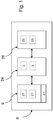
- a controller 8 for monitoring and controlling industrial process control equipment generally comprises an input assembly 9 comprising one or more input modules 27, a processor assembly 24 comprising one or more processing modules 3 and an output assembly 26 comprising one or more output modules 25. It will be appreciated that various different configurations using different numbers of modules will provide different SILs. Where an assembly provides more than one module for redundancy purposes it may be possible to replace a failed module with a replacement module whilst the industrial process control system is operational (i.e. online replacement is possible without having to perform a system shutdown). Online replacement is not possible for a simplex assembly without interruption to the process.
- Input assembly 9 receives signals from sensors monitoring industrial process control equipment via a field conditioning circuit 41 which transforms the signal to a desired voltage range and distributes the signal to the input module(s) as required.
- the input module reads the signal and then passes resulting data to the processor assembly 24 for analysis. After analysing the received input data the processor assembly sends command data to the output assembly 26 which generates drive signals to control the industrial process control equipment.
- the input sensor signals and output drive signals are sent over separate analogue current loops.
- Analogue current loops are used where a field device is to be monitored or controlled remotely over a pair of conductors. Only one current level can be present at any one time.
- the output module of the present invention uses a 4-20mA (four to twenty milliamp current loop) which is an analogue electrical transmission standard for industrial instrumentation and communication.
- the signal is provided via a current loop where 4mA represents zero percent signal and 20mA represents the one hundred percent signal. Use of a 4mA signal to represent zero allows an open circuit condition to be detected.
- the output module of the present invention also uses the Highway Addressable Remote Transducer (HART) Communications Protocol which is a digital industrial automation protocol which can communicate over legacy 4-20mA analogue instrumentation wiring, sharing the pair of wires used by the older system.
- HART Highway Addressable Remote Transducer
- the HART protocol makes use of the Bell 202 compatible Frequency Shift Keying (FSK) to superimpose digital communication signals at a low level on top of the 4-20mA.
- Bell 202 compatible systems use 1,200 Hz for the mark tone (a '1') and 2,200 Hz for the space tone (a '0').
- the HART protocol communicates at 1200 bps without interrupting the 4-20mA signal and allows a host application to obtain two or more digital updates per second from a field device. As the digital FSK signal is phase continuous, there is no interference with the 4-20mA signal.
- the analogue output module 25 comprises an I/O bus interface in the form of a field programmable gate array (FPGA) 12 which receives a command signal 10 from a processing module 3 and send a response signals 11 to a processing module 3.
- the FPGA 12 communicates with an availability management unit 14 and a safety management unit 13 in an output channel 17.
- the output channel 17 further comprises a channel output drive 21, to drive the 4-20mA loop signal 22, 23, the channel output drive 21 comprising an output current controller 15 and cutoff switches 16.
- the availability management unit 14 and the safety management unit 13 residing on an output module 25 communicate with corresponding units of a partner analogue output channel 17' residing on a partner output module 25' via signal buses 132 and 142.
- Figure 3 is a diagram illustrating schematically connections between an analogue output channel 17 driving a field termination assembly 30 and a partner analogue output channel 17'. Communication messages between the analogue output channel 17 and the partner analogue output channel 17' will be described in more detail later.
- FIG. 4 is a diagram illustrating the availability management unit (AMU) 14 in more detail.
- the availability management unit receives loop voltage input signal(s) 19 comprising a first positive voltage monitor signal 191 and a second negative voltage monitor signal 192.
- the AMU receives a voltage reference signal 42 and a AOUT drive signal 49 from the current output controller 15 and generates a current control drive signal 43 in dependence on the input signals to drive the output current controller 15.
- the AMU 14 comprises a microcomputer 47, a HART filter 45 to filter the HART element of the input voltage signal(s) 19 and generate HART filtered signal(s) 44.
- the microcomputer 47 generates a square wave signal 50 to drive a HART Compliance Filter 46 to create a HART compliant signal 48 to be superimposed on the 4-20mA loop output signal.
- the availability management unit communicates with a partner AMU within the partner analogue output channel 17' via signal bus 142, with I/O bus interface 12 via signal bus 141 and with the safety management unit (SMU) 13 via signal bus 143.
- Figure 5 is a diagram illustrating schematically the signals that pass between the various modules of the analogue output channel 17.
- the safety management unit 13 receives and validates safety commands via a communications bus 131 from the FPGA 12 and monitors the output current via a pair of current monitor signals 18 received from the channel output drive 21.
- the safety management unit also receives the following voltage signals from the channel output drive 21: voltage monitor signals 19 comprising the first voltage monitor signal 191, the second voltage monitor signal 192 and a third voltage monitor signal 193, and the output reference voltage 42.
- the safety management unit comprises a microprocessor which controls cutoff switches 16 in the channel output drive by means of a pair of gate drive signals 20.
- the safety management unit 13 will cause the output channel 17 to enter a failsafe mode by causing the gate drive signals 20 to disable the current output using the cutoff switches 16.
- the safety management unit 13 periodically tests parallel shutdown paths within the cutoff switches 16.
- the safety management unit 13 also provides detection and recovery for open circuit conditions in the output channel 17.
- the channel output drive 21 comprises output current controller 60, 61 and cutoff switches 16.
- the output current controller comprises a digital to analogue converter circuit 60 and a gate circuit 61.
- the digital to analogue converter circuit 60 receives the current control drive signal 43 and returns a voltage reference signal 42.
- the digital to analogue converter circuit 60 also receives the HART compliant signal 48 and adds that to the converted current control drive signal to generate drive signal 49 to drive the gate circuit 61.
- Cutoff switches 16 comprise cutoff switch 1 and cutoff switch 2 connected in parallel such that both cutoff switches need to be disabled in order to disable the 4-20mA current signals 22, 23 and effectively disable the output module, putting it into a failsafe state.
- Cutoff switch 62 is driven by gate drive signal 202, cutoff switch 63 is driven by gate drive signal 201.
- Current monitor signals 181 and 182 are used to monitor the current flowing through each cutoff switch respectively.
- Voltage monitor signal 191, 192 and 193 are returned to both the availability management unit 14 and the safety management unit 13.
- Command and response messages sent over signal busses 131, 132, 141, 142, 143 comprise packets of data containing a command/response byte and a data field. The content and permitted value of the data field depends upon the particular command/response being sent.
- the command byte informs the receiving entity the command to be performed for example the I/O bus interface 12 may request data relating to the monitored voltages or currents, may send commands to set or reset various parameters to be used by the availability management unit 14 or the safety management unit 13 or may send commands instructing the availability management unit 14 or the safety management unit 13 to change state.
- Offline mode 80 allows calibration constants and safety thresholds to be set and saved to memory.
- Program mode 81 allows code in the relevant microprocessor to be updated.
- online mode 82 there are four status modes. Shutdown 83, Active 84, Standby 85 and Fail-safe 86.
- the unit will change status in response to received commands from the I/O bus interface 12 and in response to changes in Analogue Output Module (AOM)/ Partner AOM or AMU-SMU Link channel status variables.
- AOM Analogue Output Module
- the availability management unit 14 and safety managements unit 13 receive and validate command messages from the I/O bus interface 12 and generate response signals to the I/O bus interface 12.
- the safety management unit 13 and the availability management unit 14 exchange status data with their corresponding partner unit 13' 14' and with each other.
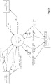
- the availability management unit 14 and the safety management unit determine a current demand independently from one another both on the basis of command signals received from the I/O bus interface 12 and on determined values of current channel status variables relating to the Analogue Output Module (AOM) channel status, Partner AOM channel status and AMU-SMU Link status.
- AOM Analogue Output Module
- Partner AOM channel status and AMU-SMU Link status.
- status values mentioned above may also be set to 'Fault' or 'Unknown'.
- the AMU 14 communicates with the partner AMU 14' in order to communicate the respective present channel status to one another
- the AMU 14 and partner AMU 14' communicate using full-duplex serial universal asynchronous receiver/transmitter (UART) links.
- the messages contain data relating to the "AOM Ch State” as well as acknowledging the presently determined "Partner AOM Ch State”. Messages are sent every 0.5ms. Failure to receive a new message within 2ms results in "Partner AOM Ch State” being set to "Unknown” and "Partner AOM Link Fault" being set to TRUE.
- the AMU 14 and SMU 13 communicate with one another via a Serial Peripheral Interface (SPI) Bus.
- the AMU is the SPI master and the SMU is the SPI slave.
- the AMU monitors the SPI link and if no data has been received from the SMU after an interval of 2ms "AMU-SMU Link Fault" is set to TRUE.
- the AMU sends data to the SMU every 1ms regarding the "AOM Ch State” and the "Partner AOM Ch State” amongst other things.
- the SMU 13 and partner SMU 13' communicate using full-duplex serial universal asynchronous receiver/transmitter (UART) links.
- the messages contain data relating to the "AOM Ch State” as well as acknowledging the presently determined "Partner AOM Ch State”. Messages are sent every 0.5ms. Failure to receive a new message within 2ms results in "Partner AOM Ch State” being set to " Unknown” and "Partner AOM Link Fault" being set to TRUE.
- the present statuses are made available to the current demand control process on the AMU 14 to determine a required current demand to be translated into a suitable drive value for the current control drive signal 43.
- a parallel SMU current demand control process operates on the SMU 13 the output of which is used by a signal monitor process which will be described in more detail later
- the basic algorithm can be quite simple: In receipt of a commanded current message from the I/O driver:
- analogue output modules could be employed each providing a proportion of the output current as long as the sum of the current demands from all of the modules remains equal to the commanded current.
- the availability management unit 14 also manages the Manage HART I/O and transmits data to the SMU 13 relating to the current status of the HART I/O link.
- the details of the HART I/O implementation are not relevant to the present invention.
- the SMU 13 has a fail safe guard band (FSGB) monitor and a gate drive controller which operate as follows.
- FSGB fail safe guard band
- the FSGB monitor monitors the loop voltage via loop voltage signals 19. If the loop voltage is less than a predetermined safety threshold (3V in the present invention) then a fault status variable indicating a line fault is set to TRUE.
- the fault status variable is used by the gate drive controller as will be described in due course.
- the FSGB monitor uses the current demand determined by the SMU's own independently generated current demand control process together with the input current signals 18 to determine whether the correct loop current is being generated by the AMU 14.
- the loop current driven by the AMU 14 is the total of the current 181 flowing through the first cutoff switch 62 and the current 182 flowing through the second cutoff switch 63.
- the monitored current signals 18 are filtered over a number of samples to remove the effect of any superimposed HART I/O signal 48
- the SMU compares the independently generated current demand (the expected current) with the total loop current (the driven current) and in the event that the difference is greater than a predetermined threshold for a predetermined period of time then a 'guard band' fault status, indicating a guard band fault is set to TRUE.
- a guard band fault status of TRUE causes the AOM CH State to be set to 'Failsafe' which in turn will cause the gate drive controller to switch off both cutoff switches.
- the guard band process uses a first threshold and a first predetermined period of time as well as a second threshold and a second predetermined period of time, the first threshold is greater than the second threshold (in the preferred embodiment of the invention it is 2 x the second threshold) and the first predetermined period of time is shorter than the second predetermined period of time.
- a guard band fault can be set if the expected current varies widely from the driven current for a shorter period or if the expected current varies by a smaller amount from the driven current for a longer period.
- the thresholds can be 'hard wired' into the control process or they may be set by commands received via the I/O bus interface 12.
- the gate drives are turned off when the AOM Ch State indicates “Ch Failsafe” OR (AOM Ch State indicates “Ch shutdown” and the Shutdown Mode is “Shutdown Off”).
- controller cycles around a sequence of gate drive control signals that alternately switch either gate off and the controller establishes that:
- the gate drive controller provides an improvement on presently available cutoff or isolation switches because the gates are constantly tested whilst operating under live conditions so a faulty gate is very quickly identified and isolated.
- the gates do not need to be tested at any particular intervals. However, they are preferably tested at an interval less than the mean time to detect a fault appropriate to a low demand system. It is preferred to alternate between the cutoff switches between every 100ms and 30s.
Landscapes
- Physics & Mathematics (AREA)
- General Physics & Mathematics (AREA)
- Engineering & Computer Science (AREA)
- Automation & Control Theory (AREA)
- Safety Devices In Control Systems (AREA)
Claims (14)
- Vorrichtung für industrielle Prozesssteuerung, umfassend ein oder mehrere Eingabemodule (27), ein oder mehrere Verarbeitungsmodule (3) und ein oder mehrere analoge Ausgabemodule (25), ein analoges Ausgabemodul (25) des einen oder der mehreren analogen Ausgabemodule (25) umfassend:eine Ausgabetreiberschaltung (21);ein Paar paralleler Ausschalter (62, 63);eine Verfügbarkeitsverwaltungseinheit (14), die ein erstes Signal empfängt, das einen angewiesenen Strom angibt und ein Signal (43) zum Steuern der Ausgabetreiberschaltung (21) zum Erzeugen eines ersten angesteuerten Stroms bestimmt; undeine Sicherheitsverwaltungseinheit (13), die ein zweites Signal, das den angewiesenen Strom angibt, und ein Signal (18), das den ersten angesteuerten Strom angibt, empfängt; und die Sicherheitsverwaltungseinheit (13) umfassend Mittel zum Bestimmen eines erwarteten ersten angesteuerten Stroms und einer Differenz zwischen dem ersten angesteuerten Strom und dem erwarteten ersten angesteuerten Strom und Ansteuern des Paars paralleler Ausschalter (62, 63) zum Deaktivieren des ersten angesteuerten Stroms in dem Fall, dass die Differenz zwischen dem ersten angesteuerten Strom und dem erwarteten ersten angesteuerten Strom größer ist als ein im Voraus bestimmter Schwellenwert und wobei der Betrieb der Sicherheitsverwaltungseinheit angeordnet ist, die Ausschalter abwechselnd derart anzusteuern, dassein erster einer des Paars paralleler Ausschalter ausgeschaltet wird;ein zweiter einer des Paars paralleler Ausschalter eingeschaltet bleibt; unddie Sicherheitsverwaltungseinheit bestimmt, ob der Strom (181) in dem ersten einen des Paars paralleler Ausschalter unter einem im Voraus bestimmten minimalen Stromschwellenwert ist; oderder erste eine des Paars paralleler Ausschalter eingeschaltet wird;der zweite eine des Paars paralleler Ausschalter ausgeschaltet wird;die Sicherheitsverwaltungseinheit bestimmt, ob der Strom (182) in dem zweiten einen des Paars paralleler Ausschalter unter dem im Voraus bestimmten minimalen Stromschwellenwert ist; undin dem Fall, dass ein beliebiger einer des Paars paralleler Ausschalter Strom über dem im Voraus bestimmten Schwellenwert gestattet, wenn er ausgeschaltet ist, die Sicherheitsverwaltungseinheit den analogen Ausgabekanal auf fehlersicher stellen wird.
- Vorrichtung nach Anspruch 1, wobei der erste angesteuerte Strom einen ersten Anteil des angewiesenen Stroms umfasst und wobei die Vorrichtung ferner ein zweites analoges Ausgabemodul umfasst, umfassend:eine zweite Verfügbarkeitsverwaltungseinheit (14'), die ein drittes Signal empfängt, das den angewiesenen Strom angibt und ein Signal zum Steuern einer Ausgabetreiberschaltung zum Erzeugen eines zweiten angesteuerten Stroms, der einen zweiten Anteil des angewiesenen Stroms umfasst, bestimmt; undeine zweite Sicherheitsverwaltungseinheit (13'), die ein viertes Signal, das den angewiesenen Strom angibt, und ein Signal (18'), das den zweiten angesteuerten Strom angibt, empfängt; und die zweite Sicherheitsverwaltungseinheit (13') umfassend Mittel zum Bestimmen eines erwarteten zweiten angesteuerten Stroms und einer Differenz zwischen dem zweiten angesteuerten Strom und dem erwarteten zweiten angesteuerten Strom; und angeordnet zum Ansteuern eines zweiten Paars paralleler Ausschalter, angeordnet zum Deaktivieren des zweiten angesteuerten Stroms in dem Fall, dass die Differenz zwischen dem zweiten angesteuerten Strom und dem erwarteten zweiten angesteuerten Strom größer ist als der im Voraus bestimmte Schwellenwert.
- Vorrichtung nach Anspruch 2, wobei die Summe des ersten Anteils und des zweiten Anteils gleich dem angewiesenen Strom ist.
- Vorrichtung nach Anspruch 3, wobei in dem Fall, dass der erste angesteuerte Strom deaktiviert wird, die zweite Verfügbarkeitsverwaltungseinheit (14') angeordnet ist, den zweiten Anteil gleich dem angewiesenen Strom einzustellen.
- Vorrichtung nach Anspruch 3, wobei in dem Fall, dass der zweite angesteuerte Strom deaktiviert wird, die zweite Verfügbarkeitsverwaltungseinheit (14') angeordnet ist, den ersten Anteil gleich dem angewiesenen Strom einzustellen.
- Vorrichtung nach einem der Ansprüche 3, 4 oder 5, wobei der erste Anteil und der zweite Anteil gleich 50 % des angewiesenen Stroms sind.
- Vorrichtung nach einem der vorstehenden Ansprüche, wobei das Paar paralleler Ausschalter angeordnet ist, im Betrieb den ersten angesteuerten Strom in dem Fall zu deaktivieren, dass die Differenz zwischen dem ersten angesteuerten Strom und dem erwarteten ersten angesteuerten Strom größer ist als ein erster im Voraus bestimmter Schwellenwert für eine erste im Voraus bestimmte Zeit, oder in dem Fall, dass die Differenz zwischen dem ersten angesteuerten Strom und dem erwarteten ersten angesteuerten Strom größer ist als ein zweiter im Voraus bestimmter Schwellenwert für eine zweite im Voraus bestimmte Zeit, und wobei der erste im Voraus bestimmte Schwellenwert größer ist als der zweite im Voraus bestimmte Schwellenwert und die erste im Voraus bestimmte Zeit kürzer ist als die zweite im Voraus bestimmte Zeit.
- Verfahren zum Testen von Ausschaltern in einer industriellen Prozesssteuerung, umfassend ein oder mehrere Eingabemodule (27), ein oder mehrere Verarbeitungsmodule (3) und ein oder mehrere analoge Ausgabemodule (25), das Verfahren umfassend:Empfangen, durch eine Verfügbarkeitsverwaltungseinheit (14), eines ersten Signals, das einen angewiesenen Strom angibt und ein Signal (43) zum Steuern einer Ausgabetreiberschaltung (21) zum Erzeugen eines ersten angesteuerten Stroms bestimmt; undEmpfangen, durch eine Sicherheitsverwaltungseinheit (13), eines zweiten Signals, das den angewiesenen Strom angibt, und eines Signals (18), das den ersten angesteuerten Strom angibt; und Bestimmen eines erwarteten ersten angesteuerten Stroms und einer Differenz zwischen dem ersten angesteuerten Strom und dem erwarteten ersten angesteuerten Strom und Ansteuern eines Paars paralleler Ausschalter (62, 63) zum Deaktivieren des ersten angesteuerten Stroms in dem Fall, dass die Differenz zwischen dem ersten angesteuerten Strom und dem erwarteten ersten angesteuerten Strom größer ist als ein im Voraus bestimmter Schwellenwert, wobei die Ausschalter abwechselnd ein- und ausgeschaltet werden, das Verfahren ferner umfassend:Einschalten/Eingeschaltetlassen eines zweiten einen des Paars paralleler Ausschalter;Ausschalten eines ersten einen des Paars paralleler Ausschalter;
undBestimmen, ob der Strom (181) in dem ersten einen des Paars paralleler Ausschalter unter einem im Voraus bestimmten minimalen Stromschwellenwert ist; oderEinschalten des ersten einen des Paars paralleler Ausschalter;Ausschalten des zweiten einen des Paars paralleler Ausschalter;Bestimmen, ob der Strom (182) in dem zweiten einen des Paars paralleler Ausschalter unter dem im Voraus bestimmten minimalen Stromschwellenwert ist; und in dem Fall, dass ein beliebiger einer des Paars paralleler Schalter Strom über dem im Voraus bestimmten Schwellenwert gestattet, wenn er ausgeschaltet ist, Einstellen des analogen Ausgabekanals auf fehlersicher. - Verfahren nach Anspruch 8, wobei der erste angesteuerte Strom einen ersten Anteil des angewiesenen Stroms umfasst, ferner umfassend:Empfangen, durch eine zweite Verfügbarkeitsverwaltungseinheit (14'), eines dritten Signals, das den angewiesenen Strom angibt, und Bestimmen eines Signals zum Steuern einer Ausgabetreiberschaltung zum Erzeugen eines zweiten angesteuerten Stroms, der einen zweiten Anteil des angewiesenen Stroms umfasst; undEmpfangen, durch eine zweite Sicherheitsverwaltungseinheit (13'), eines vierten Signals, das den angewiesenen Strom angibt, und eines Signals (18'), das den zweiten angesteuerten Strom angibt; Bestimmen eines erwarteten zweiten angesteuerten Stroms und einer Differenz zwischen dem zweiten angesteuerten Strom und dem erwarteten zweiten angesteuerten Strom; undDeaktivieren des zweiten angesteuerten Stroms in dem Fall, dass die Differenz zwischen dem zweiten angesteuerten Strom und dem erwarteten zweiten angesteuerten Strom größer ist als der im Voraus bestimmte Schwellenwert.
- Verfahren nach Anspruch 9, wobei die Summe des ersten Anteils und des zweiten Anteils gleich dem angewiesenen Strom ist.
- Verfahren nach Anspruch 10, wobei in dem Fall, dass der erste angesteuerte Strom deaktiviert wird, der zweite Anteil gleich dem angewiesenen Strom eingestellt wird.
- Verfahren nach Anspruch 10, wobei in dem Fall, dass der zweite angesteuerte Strom deaktiviert wird, der erste Anteil gleich dem angewiesenen Strom eingestellt wird.
- Verfahren nach einem der Ansprüche 10, 11 oder 12, wobei der erste Anteil und der zweite Anteil gleich 50 % des angewiesenen Stroms sind.
- Verfahren nach einem der Ansprüche 9 bis 13, umfassend die Schritte des Deaktivierens des ersten angesteuerten Stroms in dem Fall, dass die Differenz zwischen dem ersten angesteuerten Strom und dem erwarteten ersten angesteuerten Strom größer ist als ein erster im Voraus bestimmter Schwellenwert für eine erste im Voraus bestimmte Zeit, oder in dem Fall, dass die Differenz zwischen dem ersten angesteuerten Strom und dem erwarteten ersten angesteuerten Strom größer ist als ein zweiter im Voraus bestimmter Schwellenwert für eine zweite im Voraus bestimmte Zeit, und wobei der erste im Voraus bestimmte Schwellenwert größer ist als der zweite im Voraus bestimmte Schwellenwert und die erste im Voraus bestimmte Zeit kürzer ist als die zweite im Voraus bestimmte Zeit.
Priority Applications (1)
| Application Number | Priority Date | Filing Date | Title |
|---|---|---|---|
| US13/678,775 US9182754B2 (en) | 2011-11-17 | 2012-11-16 | Method and apparatus for analogue output current control |
Applications Claiming Priority (1)
| Application Number | Priority Date | Filing Date | Title |
|---|---|---|---|
| US201161561089P | 2011-11-17 | 2011-11-17 |
Publications (3)
| Publication Number | Publication Date |
|---|---|
| EP2595019A2 EP2595019A2 (de) | 2013-05-22 |
| EP2595019A3 EP2595019A3 (de) | 2014-12-03 |
| EP2595019B1 true EP2595019B1 (de) | 2019-03-13 |
Family
ID=45531253
Family Applications (2)
| Application Number | Title | Priority Date | Filing Date |
|---|---|---|---|
| EP12153386.3A Active EP2595019B1 (de) | 2011-11-17 | 2012-01-31 | Verfahren und Vorrichtung zur Steuerung von analogem Ausgangsstrom |
| EP12153371.5A Not-in-force EP2595018B1 (de) | 2011-11-17 | 2012-01-31 | Verfahren und Vorrichtung zur Steuerung von analogem Ausgangsstrom |
Family Applications After (1)
| Application Number | Title | Priority Date | Filing Date |
|---|---|---|---|
| EP12153371.5A Not-in-force EP2595018B1 (de) | 2011-11-17 | 2012-01-31 | Verfahren und Vorrichtung zur Steuerung von analogem Ausgangsstrom |
Country Status (2)
| Country | Link |
|---|---|
| US (2) | US9182754B2 (de) |
| EP (2) | EP2595019B1 (de) |
Families Citing this family (8)
| Publication number | Priority date | Publication date | Assignee | Title |
|---|---|---|---|---|
| US9651931B2 (en) * | 2015-03-11 | 2017-05-16 | Rockwell Automation Technologies, Inc. | Industrial control system with integrated circuit elements partitioned for functional safety and employing watchdog timing circuits |
| CN106292458B (zh) * | 2016-09-30 | 2020-03-17 | 株洲中车时代电气股份有限公司 | 一种具有防止意外动作功能的屏蔽门控制装置及控制方法 |
| IT201600127390A1 (it) * | 2016-12-16 | 2018-06-16 | Sanco S P A | Centrale antincendio |
| US10663929B2 (en) * | 2018-03-20 | 2020-05-26 | Fisher-Rosemount Systems, Inc. | Long-haul safety system trips |
| CN108829006B (zh) * | 2018-06-29 | 2024-11-12 | 北京广利核系统工程有限公司 | 可选择性输出电压或电流的模拟量输出装置和方法 |
| US11491930B2 (en) * | 2019-12-03 | 2022-11-08 | Woodward, Inc. | Systems and methods for commanded or uncommanded channel switchover in a multiple processor controller |
| CN112925250B (zh) * | 2021-03-05 | 2022-06-21 | 广州市微生物研究所有限公司 | 等离子体空气净化器电参数老化试验控制方法及控制电路 |
| US11546016B2 (en) * | 2021-03-18 | 2023-01-03 | Texas Instruments Incorporated | Pseudo-sinusoidal waveform generator for HART communication |
Family Cites Families (22)
| Publication number | Priority date | Publication date | Assignee | Title |
|---|---|---|---|---|
| US4024371A (en) * | 1974-12-18 | 1977-05-17 | Kelsey-Hayes Company | Welding monitoring and control system |
| US4527247A (en) * | 1981-07-31 | 1985-07-02 | Ibg International, Inc. | Environmental control system |
| US4868826A (en) * | 1987-08-31 | 1989-09-19 | Triplex | Fault-tolerant output circuits |
| US4926281A (en) * | 1989-02-27 | 1990-05-15 | Triplex | Fail-safe and fault-tolerant alternating current output circuit |
| US5233231A (en) | 1991-11-29 | 1993-08-03 | Pepperl + Fuchs, Inc. | Control-safe capacitive switch |
| FR2715738B1 (fr) * | 1994-01-31 | 1996-04-12 | Sextant Avionique | Interrupteur composite de sécurité. |
| US5986480A (en) | 1997-12-22 | 1999-11-16 | Advanced Micro Devices, Inc. | Multiple input zero power AND/NOR gate for use in a field programmable gate array (FPGA) |
| US6550018B1 (en) * | 2000-02-18 | 2003-04-15 | The University Of Akron | Hybrid multiple redundant computer system |
| US6503649B1 (en) | 2000-04-03 | 2003-01-07 | Convergence, Llc | Variable fuel cell power system for generating electrical power |
| US6618628B1 (en) * | 2000-10-05 | 2003-09-09 | Karl A. Davlin | Distributed input/output control systems and methods |
| US6459173B1 (en) | 2000-10-30 | 2002-10-01 | Rockwell Automation Technologies, Inc. | Self-programmable battery load/bias for memory expansion module |
| JP2003031000A (ja) | 2001-07-12 | 2003-01-31 | Oki Electric Ind Co Ltd | 半導体記憶装置 |
| US7532955B2 (en) * | 2002-02-25 | 2009-05-12 | General Electric Company | Distributed protection system for power distribution systems |
| DE10307999B4 (de) * | 2003-02-25 | 2007-03-01 | Siemens Ag | Antriebssteuereinrichtung für einen selbstgeführten Stromrichter |
| GB2427940A (en) * | 2005-07-01 | 2007-01-10 | Ics Triplex Technology Ltd | Turbo machinery speed monitor |
| US7582989B2 (en) * | 2006-09-29 | 2009-09-01 | Fisher-Rosemount Systems, Inc. | Safety relay having independently testable contacts |
| US7680550B2 (en) | 2006-10-20 | 2010-03-16 | Rockwell Automation Technologies, Inc. | Unit module state processing enhancements |
| US8132035B2 (en) * | 2007-05-25 | 2012-03-06 | Raven Technology Group, LLC | Ethernet interface |
| WO2009155993A1 (en) * | 2008-06-27 | 2009-12-30 | Abb Research Ltd. | A safety system for a machine |
| US8175463B2 (en) | 2008-09-24 | 2012-05-08 | Elbex Video Ltd. | Method and apparatus for connecting AC powered switches, current sensors and control devices via two way IR, fiber optic and light guide cables |
| EP2254108A1 (de) | 2009-05-20 | 2010-11-24 | Dialog Semiconductor GmbH | Ansteuerung erweiterter mehrzeiliger Adressen |
| US9280930B2 (en) * | 2009-05-20 | 2016-03-08 | Dialog Semiconductor Gmbh | Back to back pre-charge scheme |
-
2012
- 2012-01-31 EP EP12153386.3A patent/EP2595019B1/de active Active
- 2012-01-31 EP EP12153371.5A patent/EP2595018B1/de not_active Not-in-force
- 2012-11-16 US US13/678,775 patent/US9182754B2/en active Active
- 2012-11-16 US US13/678,704 patent/US10222770B2/en active Active
Non-Patent Citations (1)
| Title |
|---|
| None * |
Also Published As
| Publication number | Publication date |
|---|---|
| EP2595019A2 (de) | 2013-05-22 |
| US20130131834A1 (en) | 2013-05-23 |
| US20130131832A1 (en) | 2013-05-23 |
| EP2595018B1 (de) | 2019-01-23 |
| EP2595018A2 (de) | 2013-05-22 |
| EP2595018A3 (de) | 2014-12-03 |
| US10222770B2 (en) | 2019-03-05 |
| US9182754B2 (en) | 2015-11-10 |
| EP2595019A3 (de) | 2014-12-03 |
Similar Documents
| Publication | Publication Date | Title |
|---|---|---|
| EP2595019B1 (de) | Verfahren und Vorrichtung zur Steuerung von analogem Ausgangsstrom | |
| US10229016B2 (en) | Redundant computer system utilizing comparison diagnostics and voting techniques | |
| CN102077453B (zh) | 用于可靠安全系统停机的具有多通信设备的分布式和自适应智能逻辑 | |
| EP3806226A1 (de) | Redundante spannungsmessungen für batterieverwaltungssysteme | |
| US20070147232A1 (en) | Redundant supervisory control system, and redundancy switching method of the same | |
| WO1993020488A2 (en) | Process control interface system having triply redundant remote field units | |
| US10579558B1 (en) | Flexible redundant input/output (I/O) schemes for I/O channels | |
| CN102096401A (zh) | 基于现场总线和arm处理器的冗余容错安全仪表系统 | |
| CN107924722B (zh) | 核电站安全管理系统 | |
| CN85109748A (zh) | 基于对复杂过程的传感器信号处理系统的分布式微处理机 | |
| CN103631251A (zh) | 便携式仪器维护辅助装置、系统及方法 | |
| CN107484430A (zh) | 一种用于核电厂的安全系统及其操作方法 | |
| CN105759781A (zh) | 机器人的布线方法 | |
| CN105103061A (zh) | 控制和数据传输设备、处理装置和具有分散冗余的用于冗余的过程控制的方法 | |
| KR20160081575A (ko) | 제어기의 이중화 시스템 | |
| EP3557344A1 (de) | Windturbinenfehlerüberwachungssystem und -verfahren | |
| US6161202A (en) | Method for the monitoring of integrated circuits | |
| EP1837992B1 (de) | Überlastungsschutz für ein digitales Ausgangsmodul | |
| EP1785791B1 (de) | Programmierbare steuerung | |
| CN104267642A (zh) | 一种输出可靠电流信号的系统及方法 | |
| EP4184262B1 (de) | Koordinierung des einfügens und/oder entfernens von redundanten ein-/ausgabekomponenten | |
| EP2413300B1 (de) | Verfahren und Vorrichtung zum Senden und Empfangen von HART-Kommunikationsübertragungswellenformen | |
| RU2331899C2 (ru) | Устройство обработки с цепью отключения | |
| CN113671931B (zh) | 一种安全信号采集器 | |
| CN114978874A (zh) | 一种多重化热备冗余系统 |
Legal Events
| Date | Code | Title | Description |
|---|---|---|---|
| PUAI | Public reference made under article 153(3) epc to a published international application that has entered the european phase |
Free format text: ORIGINAL CODE: 0009012 |
|
| AK | Designated contracting states |
Kind code of ref document: A2 Designated state(s): AL AT BE BG CH CY CZ DE DK EE ES FI FR GB GR HR HU IE IS IT LI LT LU LV MC MK MT NL NO PL PT RO RS SE SI SK SM TR |
|
| AX | Request for extension of the european patent |
Extension state: BA ME |
|
| RIN1 | Information on inventor provided before grant (corrected) |
Inventor name: MURRELL, SHELBY ADAM Inventor name: AGAR, PHILIP J. Inventor name: MEAGHER, THOMAS BRUCE Inventor name: CREECH, GERALD R. Inventor name: JONES, IAN DAVID WYNNE |
|
| PUAL | Search report despatched |
Free format text: ORIGINAL CODE: 0009013 |
|
| AK | Designated contracting states |
Kind code of ref document: A3 Designated state(s): AL AT BE BG CH CY CZ DE DK EE ES FI FR GB GR HR HU IE IS IT LI LT LU LV MC MK MT NL NO PL PT RO RS SE SI SK SM TR |
|
| AX | Request for extension of the european patent |
Extension state: BA ME |
|
| RIC1 | Information provided on ipc code assigned before grant |
Ipc: G05B 9/03 20060101ALI20141029BHEP Ipc: G05B 19/05 20060101ALI20141029BHEP Ipc: G05B 19/042 20060101AFI20141029BHEP |
|
| 17P | Request for examination filed |
Effective date: 20150602 |
|
| RBV | Designated contracting states (corrected) |
Designated state(s): AL AT BE BG CH CY CZ DE DK EE ES FI FR GB GR HR HU IE IS IT LI LT LU LV MC MK MT NL NO PL PT RO RS SE SI SK SM TR |
|
| 17Q | First examination report despatched |
Effective date: 20160520 |
|
| STAA | Information on the status of an ep patent application or granted ep patent |
Free format text: STATUS: EXAMINATION IS IN PROGRESS |
|
| GRAP | Despatch of communication of intention to grant a patent |
Free format text: ORIGINAL CODE: EPIDOSNIGR1 |
|
| STAA | Information on the status of an ep patent application or granted ep patent |
Free format text: STATUS: GRANT OF PATENT IS INTENDED |
|
| INTG | Intention to grant announced |
Effective date: 20180917 |
|
| GRAS | Grant fee paid |
Free format text: ORIGINAL CODE: EPIDOSNIGR3 |
|
| GRAJ | Information related to disapproval of communication of intention to grant by the applicant or resumption of examination proceedings by the epo deleted |
Free format text: ORIGINAL CODE: EPIDOSDIGR1 |
|
| GRAL | Information related to payment of fee for publishing/printing deleted |
Free format text: ORIGINAL CODE: EPIDOSDIGR3 |
|
| STAA | Information on the status of an ep patent application or granted ep patent |
Free format text: STATUS: EXAMINATION IS IN PROGRESS |
|
| GRAR | Information related to intention to grant a patent recorded |
Free format text: ORIGINAL CODE: EPIDOSNIGR71 |
|
| STAA | Information on the status of an ep patent application or granted ep patent |
Free format text: STATUS: GRANT OF PATENT IS INTENDED |
|
| INTC | Intention to grant announced (deleted) | ||
| GRAA | (expected) grant |
Free format text: ORIGINAL CODE: 0009210 |
|
| STAA | Information on the status of an ep patent application or granted ep patent |
Free format text: STATUS: THE PATENT HAS BEEN GRANTED |
|
| INTG | Intention to grant announced |
Effective date: 20190109 |
|
| AK | Designated contracting states |
Kind code of ref document: B1 Designated state(s): AL AT BE BG CH CY CZ DE DK EE ES FI FR GB GR HR HU IE IS IT LI LT LU LV MC MK MT NL NO PL PT RO RS SE SI SK SM TR |
|
| REG | Reference to a national code |
Ref country code: GB Ref legal event code: FG4D |
|
| REG | Reference to a national code |
Ref country code: CH Ref legal event code: EP Ref country code: AT Ref legal event code: REF Ref document number: 1108546 Country of ref document: AT Kind code of ref document: T Effective date: 20190315 |
|
| REG | Reference to a national code |
Ref country code: IE Ref legal event code: FG4D |
|
| REG | Reference to a national code |
Ref country code: DE Ref legal event code: R096 Ref document number: 602012057661 Country of ref document: DE |
|
| REG | Reference to a national code |
Ref country code: NL Ref legal event code: MP Effective date: 20190313 |
|
| REG | Reference to a national code |
Ref country code: LT Ref legal event code: MG4D |
|
| PG25 | Lapsed in a contracting state [announced via postgrant information from national office to epo] |
Ref country code: SE Free format text: LAPSE BECAUSE OF FAILURE TO SUBMIT A TRANSLATION OF THE DESCRIPTION OR TO PAY THE FEE WITHIN THE PRESCRIBED TIME-LIMIT Effective date: 20190313 Ref country code: FI Free format text: LAPSE BECAUSE OF FAILURE TO SUBMIT A TRANSLATION OF THE DESCRIPTION OR TO PAY THE FEE WITHIN THE PRESCRIBED TIME-LIMIT Effective date: 20190313 Ref country code: NO Free format text: LAPSE BECAUSE OF FAILURE TO SUBMIT A TRANSLATION OF THE DESCRIPTION OR TO PAY THE FEE WITHIN THE PRESCRIBED TIME-LIMIT Effective date: 20190613 Ref country code: LT Free format text: LAPSE BECAUSE OF FAILURE TO SUBMIT A TRANSLATION OF THE DESCRIPTION OR TO PAY THE FEE WITHIN THE PRESCRIBED TIME-LIMIT Effective date: 20190313 |
|
| PG25 | Lapsed in a contracting state [announced via postgrant information from national office to epo] |
Ref country code: BG Free format text: LAPSE BECAUSE OF FAILURE TO SUBMIT A TRANSLATION OF THE DESCRIPTION OR TO PAY THE FEE WITHIN THE PRESCRIBED TIME-LIMIT Effective date: 20190613 Ref country code: GR Free format text: LAPSE BECAUSE OF FAILURE TO SUBMIT A TRANSLATION OF THE DESCRIPTION OR TO PAY THE FEE WITHIN THE PRESCRIBED TIME-LIMIT Effective date: 20190614 Ref country code: NL Free format text: LAPSE BECAUSE OF FAILURE TO SUBMIT A TRANSLATION OF THE DESCRIPTION OR TO PAY THE FEE WITHIN THE PRESCRIBED TIME-LIMIT Effective date: 20190313 Ref country code: LV Free format text: LAPSE BECAUSE OF FAILURE TO SUBMIT A TRANSLATION OF THE DESCRIPTION OR TO PAY THE FEE WITHIN THE PRESCRIBED TIME-LIMIT Effective date: 20190313 Ref country code: HR Free format text: LAPSE BECAUSE OF FAILURE TO SUBMIT A TRANSLATION OF THE DESCRIPTION OR TO PAY THE FEE WITHIN THE PRESCRIBED TIME-LIMIT Effective date: 20190313 Ref country code: RS Free format text: LAPSE BECAUSE OF FAILURE TO SUBMIT A TRANSLATION OF THE DESCRIPTION OR TO PAY THE FEE WITHIN THE PRESCRIBED TIME-LIMIT Effective date: 20190313 |
|
| REG | Reference to a national code |
Ref country code: AT Ref legal event code: MK05 Ref document number: 1108546 Country of ref document: AT Kind code of ref document: T Effective date: 20190313 |
|
| PG25 | Lapsed in a contracting state [announced via postgrant information from national office to epo] |
Ref country code: RO Free format text: LAPSE BECAUSE OF FAILURE TO SUBMIT A TRANSLATION OF THE DESCRIPTION OR TO PAY THE FEE WITHIN THE PRESCRIBED TIME-LIMIT Effective date: 20190313 Ref country code: SK Free format text: LAPSE BECAUSE OF FAILURE TO SUBMIT A TRANSLATION OF THE DESCRIPTION OR TO PAY THE FEE WITHIN THE PRESCRIBED TIME-LIMIT Effective date: 20190313 Ref country code: CZ Free format text: LAPSE BECAUSE OF FAILURE TO SUBMIT A TRANSLATION OF THE DESCRIPTION OR TO PAY THE FEE WITHIN THE PRESCRIBED TIME-LIMIT Effective date: 20190313 Ref country code: IT Free format text: LAPSE BECAUSE OF FAILURE TO SUBMIT A TRANSLATION OF THE DESCRIPTION OR TO PAY THE FEE WITHIN THE PRESCRIBED TIME-LIMIT Effective date: 20190313 Ref country code: EE Free format text: LAPSE BECAUSE OF FAILURE TO SUBMIT A TRANSLATION OF THE DESCRIPTION OR TO PAY THE FEE WITHIN THE PRESCRIBED TIME-LIMIT Effective date: 20190313 Ref country code: AL Free format text: LAPSE BECAUSE OF FAILURE TO SUBMIT A TRANSLATION OF THE DESCRIPTION OR TO PAY THE FEE WITHIN THE PRESCRIBED TIME-LIMIT Effective date: 20190313 Ref country code: ES Free format text: LAPSE BECAUSE OF FAILURE TO SUBMIT A TRANSLATION OF THE DESCRIPTION OR TO PAY THE FEE WITHIN THE PRESCRIBED TIME-LIMIT Effective date: 20190313 Ref country code: PT Free format text: LAPSE BECAUSE OF FAILURE TO SUBMIT A TRANSLATION OF THE DESCRIPTION OR TO PAY THE FEE WITHIN THE PRESCRIBED TIME-LIMIT Effective date: 20190713 |
|
| PG25 | Lapsed in a contracting state [announced via postgrant information from national office to epo] |
Ref country code: PL Free format text: LAPSE BECAUSE OF FAILURE TO SUBMIT A TRANSLATION OF THE DESCRIPTION OR TO PAY THE FEE WITHIN THE PRESCRIBED TIME-LIMIT Effective date: 20190313 Ref country code: SM Free format text: LAPSE BECAUSE OF FAILURE TO SUBMIT A TRANSLATION OF THE DESCRIPTION OR TO PAY THE FEE WITHIN THE PRESCRIBED TIME-LIMIT Effective date: 20190313 |
|
| REG | Reference to a national code |
Ref country code: DE Ref legal event code: R097 Ref document number: 602012057661 Country of ref document: DE |
|
| PG25 | Lapsed in a contracting state [announced via postgrant information from national office to epo] |
Ref country code: AT Free format text: LAPSE BECAUSE OF FAILURE TO SUBMIT A TRANSLATION OF THE DESCRIPTION OR TO PAY THE FEE WITHIN THE PRESCRIBED TIME-LIMIT Effective date: 20190313 Ref country code: IS Free format text: LAPSE BECAUSE OF FAILURE TO SUBMIT A TRANSLATION OF THE DESCRIPTION OR TO PAY THE FEE WITHIN THE PRESCRIBED TIME-LIMIT Effective date: 20190713 |
|
| PLBE | No opposition filed within time limit |
Free format text: ORIGINAL CODE: 0009261 |
|
| STAA | Information on the status of an ep patent application or granted ep patent |
Free format text: STATUS: NO OPPOSITION FILED WITHIN TIME LIMIT |
|
| PG25 | Lapsed in a contracting state [announced via postgrant information from national office to epo] |
Ref country code: DK Free format text: LAPSE BECAUSE OF FAILURE TO SUBMIT A TRANSLATION OF THE DESCRIPTION OR TO PAY THE FEE WITHIN THE PRESCRIBED TIME-LIMIT Effective date: 20190313 |
|
| 26N | No opposition filed |
Effective date: 20191216 |
|
| PG25 | Lapsed in a contracting state [announced via postgrant information from national office to epo] |
Ref country code: SI Free format text: LAPSE BECAUSE OF FAILURE TO SUBMIT A TRANSLATION OF THE DESCRIPTION OR TO PAY THE FEE WITHIN THE PRESCRIBED TIME-LIMIT Effective date: 20190313 |
|
| PG25 | Lapsed in a contracting state [announced via postgrant information from national office to epo] |
Ref country code: TR Free format text: LAPSE BECAUSE OF FAILURE TO SUBMIT A TRANSLATION OF THE DESCRIPTION OR TO PAY THE FEE WITHIN THE PRESCRIBED TIME-LIMIT Effective date: 20190313 |
|
| PG25 | Lapsed in a contracting state [announced via postgrant information from national office to epo] |
Ref country code: MC Free format text: LAPSE BECAUSE OF FAILURE TO SUBMIT A TRANSLATION OF THE DESCRIPTION OR TO PAY THE FEE WITHIN THE PRESCRIBED TIME-LIMIT Effective date: 20190313 |
|
| REG | Reference to a national code |
Ref country code: CH Ref legal event code: PL |
|
| REG | Reference to a national code |
Ref country code: BE Ref legal event code: MM Effective date: 20200131 |
|
| PG25 | Lapsed in a contracting state [announced via postgrant information from national office to epo] |
Ref country code: LU Free format text: LAPSE BECAUSE OF NON-PAYMENT OF DUE FEES Effective date: 20200131 |
|
| PG25 | Lapsed in a contracting state [announced via postgrant information from national office to epo] |
Ref country code: CH Free format text: LAPSE BECAUSE OF NON-PAYMENT OF DUE FEES Effective date: 20200131 Ref country code: BE Free format text: LAPSE BECAUSE OF NON-PAYMENT OF DUE FEES Effective date: 20200131 Ref country code: LI Free format text: LAPSE BECAUSE OF NON-PAYMENT OF DUE FEES Effective date: 20200131 |
|
| PG25 | Lapsed in a contracting state [announced via postgrant information from national office to epo] |
Ref country code: IE Free format text: LAPSE BECAUSE OF NON-PAYMENT OF DUE FEES Effective date: 20200131 |
|
| PG25 | Lapsed in a contracting state [announced via postgrant information from national office to epo] |
Ref country code: MT Free format text: LAPSE BECAUSE OF FAILURE TO SUBMIT A TRANSLATION OF THE DESCRIPTION OR TO PAY THE FEE WITHIN THE PRESCRIBED TIME-LIMIT Effective date: 20190313 Ref country code: CY Free format text: LAPSE BECAUSE OF FAILURE TO SUBMIT A TRANSLATION OF THE DESCRIPTION OR TO PAY THE FEE WITHIN THE PRESCRIBED TIME-LIMIT Effective date: 20190313 |
|
| PG25 | Lapsed in a contracting state [announced via postgrant information from national office to epo] |
Ref country code: MK Free format text: LAPSE BECAUSE OF FAILURE TO SUBMIT A TRANSLATION OF THE DESCRIPTION OR TO PAY THE FEE WITHIN THE PRESCRIBED TIME-LIMIT Effective date: 20190313 |
|
| PGFP | Annual fee paid to national office [announced via postgrant information from national office to epo] |
Ref country code: GB Payment date: 20251220 Year of fee payment: 15 |
|
| PGFP | Annual fee paid to national office [announced via postgrant information from national office to epo] |
Ref country code: FR Payment date: 20251218 Year of fee payment: 15 |
|
| PGFP | Annual fee paid to national office [announced via postgrant information from national office to epo] |
Ref country code: DE Payment date: 20251217 Year of fee payment: 15 |