EP2595156A2 - Appareil de maintenance préventive et procédé d'entretien préventif pour la surface intérieure de canalisations - Google Patents
Appareil de maintenance préventive et procédé d'entretien préventif pour la surface intérieure de canalisations Download PDFInfo
- Publication number
- EP2595156A2 EP2595156A2 EP12193050.7A EP12193050A EP2595156A2 EP 2595156 A2 EP2595156 A2 EP 2595156A2 EP 12193050 A EP12193050 A EP 12193050A EP 2595156 A2 EP2595156 A2 EP 2595156A2
- Authority
- EP
- European Patent Office
- Prior art keywords
- base body
- preventive maintenance
- piping
- water
- floating bodies
- Prior art date
- Legal status (The legal status is an assumption and is not a legal conclusion. Google has not performed a legal analysis and makes no representation as to the accuracy of the status listed.)
- Withdrawn
Links
Images



Classifications
-
- G—PHYSICS
- G21—NUCLEAR PHYSICS; NUCLEAR ENGINEERING
- G21C—NUCLEAR REACTORS
- G21C17/00—Monitoring; Testing ; Maintaining
- G21C17/017—Inspection or maintenance of pipe-lines or tubes in nuclear installations
-
- B—PERFORMING OPERATIONS; TRANSPORTING
- B08—CLEANING
- B08B—CLEANING IN GENERAL; PREVENTION OF FOULING IN GENERAL
- B08B9/00—Cleaning hollow articles by methods or apparatus specially adapted thereto
- B08B9/02—Cleaning pipes or tubes or systems of pipes or tubes
- B08B9/027—Cleaning the internal surfaces; Removal of blockages
- B08B9/04—Cleaning the internal surfaces; Removal of blockages using cleaning devices introduced into and moved along the pipes
-
- F—MECHANICAL ENGINEERING; LIGHTING; HEATING; WEAPONS; BLASTING
- F16—ENGINEERING ELEMENTS AND UNITS; GENERAL MEASURES FOR PRODUCING AND MAINTAINING EFFECTIVE FUNCTIONING OF MACHINES OR INSTALLATIONS; THERMAL INSULATION IN GENERAL
- F16L—PIPES; JOINTS OR FITTINGS FOR PIPES; SUPPORTS FOR PIPES, CABLES OR PROTECTIVE TUBING; MEANS FOR THERMAL INSULATION IN GENERAL
- F16L55/00—Devices or appurtenances for use in, or in connection with, pipes or pipe systems
- F16L55/26—Pigs or moles, i.e. devices movable in a pipe or conduit with or without self-contained propulsion means
- F16L55/28—Constructional aspects
- F16L55/30—Constructional aspects of the propulsion means, e.g. towed by cables
- F16L55/32—Constructional aspects of the propulsion means, e.g. towed by cables being self-contained
- F16L55/36—Constructional aspects of the propulsion means, e.g. towed by cables being self-contained jet driven
-
- F—MECHANICAL ENGINEERING; LIGHTING; HEATING; WEAPONS; BLASTING
- F16—ENGINEERING ELEMENTS AND UNITS; GENERAL MEASURES FOR PRODUCING AND MAINTAINING EFFECTIVE FUNCTIONING OF MACHINES OR INSTALLATIONS; THERMAL INSULATION IN GENERAL
- F16L—PIPES; JOINTS OR FITTINGS FOR PIPES; SUPPORTS FOR PIPES, CABLES OR PROTECTIVE TUBING; MEANS FOR THERMAL INSULATION IN GENERAL
- F16L55/00—Devices or appurtenances for use in, or in connection with, pipes or pipe systems
- F16L55/26—Pigs or moles, i.e. devices movable in a pipe or conduit with or without self-contained propulsion means
- F16L55/28—Constructional aspects
- F16L55/40—Constructional aspects of the body
- F16L55/44—Constructional aspects of the body expandable
-
- Y—GENERAL TAGGING OF NEW TECHNOLOGICAL DEVELOPMENTS; GENERAL TAGGING OF CROSS-SECTIONAL TECHNOLOGIES SPANNING OVER SEVERAL SECTIONS OF THE IPC; TECHNICAL SUBJECTS COVERED BY FORMER USPC CROSS-REFERENCE ART COLLECTIONS [XRACs] AND DIGESTS
- Y02—TECHNOLOGIES OR APPLICATIONS FOR MITIGATION OR ADAPTATION AGAINST CLIMATE CHANGE
- Y02E—REDUCTION OF GREENHOUSE GAS [GHG] EMISSIONS, RELATED TO ENERGY GENERATION, TRANSMISSION OR DISTRIBUTION
- Y02E30/00—Energy generation of nuclear origin
- Y02E30/30—Nuclear fission reactors
-
- Y—GENERAL TAGGING OF NEW TECHNOLOGICAL DEVELOPMENTS; GENERAL TAGGING OF CROSS-SECTIONAL TECHNOLOGIES SPANNING OVER SEVERAL SECTIONS OF THE IPC; TECHNICAL SUBJECTS COVERED BY FORMER USPC CROSS-REFERENCE ART COLLECTIONS [XRACs] AND DIGESTS
- Y10—TECHNICAL SUBJECTS COVERED BY FORMER USPC
- Y10S—TECHNICAL SUBJECTS COVERED BY FORMER USPC CROSS-REFERENCE ART COLLECTIONS [XRACs] AND DIGESTS
- Y10S901/00—Robots
- Y10S901/30—End effector
- Y10S901/41—Tool
- Y10S901/43—Spray painting or coating
Definitions
- the present invention relates to a preventive maintenance apparatus and a preventive maintenance method for an inner surface of a piping and more particularly to a preventive maintenance apparatus and a preventive maintenance method for an inner surface suitable for applying to the preventive maintenance of an inside of a piping connected to a reactor pressure vessel of a nuclear power plant.
- Japanese Patent Laid-Open No. 8(1996)-5773 describes a preventive maintenance apparatus and a preventive maintenance method for performing decontamination, washing, and modification of an inner surface of a riser pipe passing through the reactor pressure vessel and reaching the inside the reactor pressure vessel, in a boiling water reactor.
- the preventive maintenance apparatus is suspended in the reactor pressure vessel from the upper portion to a predetermined position in the riser pipe and is held inside the riser pipe with a fixing leg installed in the preventive maintenance apparatus pressed to the inner surface of the riser pipe.
- an inner surface processing apparatus, an inner surface washing apparatus, an inner surface modification apparatus, and an inner surface inspection apparatus are used as a preventive maintenance apparatus. These units are held by fixing legs in the riser pipe and, for the inner surface of the riser pipe, processing, washing, modification, and inspection are performed.
- a piping inner operation apparatus having a head unit, a head swing drive unit, a curve drive unit, and a travelling drive unit is described in Japanese Patent Laid-Open No. 2008-14447 .
- An arm is rotatably attached to the body of the head swing drive unit and one end of the curve drive unit is rotatably attached to the arm.
- One end of the travelling drive unit is rotatably attached to the other end of the curve drive unit.
- the head unit is attached to a front of the body of the head swing drive unit.
- the piping inner operation apparatus is inserted into a riser pipe installed in a reactor pressure vessel from the upper end thereof.
- a jet nozzle for water jet peening is attached to the head unit and executes the water jet peening of an inner surface of the riser pipe.
- Japanese Patent Laid-Open No. 2001-264482 describes an inner surface inspection apparatus of piping.
- the inner surface inspection apparatus is inserted into a riser pipe passing through a reactor pressure vessel and installed in a reactor pressure vessel from the outside of the reactor pressure vessel and moves in the riser pipe upward from underneath.
- a head for fluorescent penetrant inspection is installed in the inner surface inspection apparatus.
- Japanese Patent Laid-Open No. 8(1996)-5773 and Japanese Patent Laid-Open No. 2008-14447 describe that the preventive maintenance apparatus is disposed in the axial direction of the reactor pressure vessel, is inserted into the piping from an opening formed at an upper end of the piping installed in the reactor pressure vessel, and moves in the piping downward from above.
- the techniques described in these applications published are methods for moving the preventive maintenance apparatus from the upper end side of the piping to a predetermined position in the piping. In these methods, when access from the upper end side of the piping is impossible, it is difficult to permit the preventive maintenance apparatus to access into the piping from a lower end side of the piping.
- the technique described in Japanese Patent Laid-Open No. 2001-264482 is a method for permitting the inner surface inspection apparatus to access from the lower end side of the piping into the piping, though the method is a method when the lower end side of the piping exists in gas and when the lower end side of the piping exists in water, it is difficult to permit the inner surface inspection apparatus to access in the piping.
- An object of the present invention is to provide a preventive maintenance apparatus and a preventive maintenance method for an inner surface capable of easily executing preventive maintenance operation for an inner surface of a piping with water filled.
- a feature of the present invention for accomplishing the above object is a preventive maintenance apparatus comprising a base body; a driving apparatus installed on the base body for advancing the base body; a water jet peening apparatus installed on the base body; a plurality of floating bodies respectively installed on a leading portion and rear of the base body; a plurality of clamp apparatuses installed on the base body for making contact with the inner surface of the piping when holding the base body in the piping; and a camera installed on the base body.
- the preventive maintenance apparatus has the plurality of floating bodies respectively installed on the leading portion and on the rear of the base body, the base body having the driving apparatus, the water jet peening apparatus, the plurality of floating bodies, the plurality of clamp apparatuses, and the camera can be easily inserted into the piping with water internally filled which is connected to the reactor pressure vessel with water filled through a opening of the piping which is released into the reactor pressure vessel, and into a vertical pipe portion of the piping including a curve pipe portion and the vertical pipe portion extended to it, the base body can be inserted from underneath. Therefore, even when the base body cannot be inserted into the piping from the upper portion, the preventive maintenance operation, that is, the water jet peening can be executed easily for the inner surface of the piping.
- the preventive maintenance operation for the inner surface of the piping with water internally filled which is connected to the reactor pressure vessel with water filled can be executed easily.
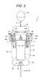
- FIGs. 1 and 2 A preventive maintenance apparatus which is a preferable embodiment of the present invention will be explained by referring to FIGs. 1 and 2 .
- a preventive maintenance apparatus 1 of the present embodiment is provided with a movable body 2 and a water jet peening apparatus 3.
- the movable body 2 has a driving apparatus 21, floating bodies 25, 26, 27, 28, 29, and 30, clamp apparatuses 48A and 48B, a base body 62, and camera units 63A and 63B.
- the water jet peening apparatus 3 has jet nozzles 4A and 4B, a cavitation generator (a water jet peening bubble generation apparatus) 4, a motor (a nozzle rotation apparatus) 7 (refer to FIG. 3 ), a high-pressure pump (a pressurized water supply apparatus) 17, and a nozzle movable unit 13 (refer to FIG. 3 ).
- the base body 62 for example, includes a cylindrical side wall, and the side wall is blocked at its both ends, thus the space is formed internally.
- the cavitation generator 4, as described later, is rotatably attached to a leading portion of the base body 62.
- the floating body 25 is attached to a leading portion of the cavitation generator 4 and the floating body 30 is connected to a front of the floating body 25 by a connection member (for example, a chain) 31.
- the floating bodies 28 and 29 are attached to the rear surface of the base body 62.
- the three floating bodies including the floating bodies 26 and 27 are attached to an outer surface of the cylindrical side wall of the base body 62 at even intervals in a peripheral direction.
- the three clamp apparatuses including the clamp apparatuses 48A and 48B are arranged on the outer surface of the cylindrical side wall of the base body 62 at mutual intervals of the floating bodies attached to the outer surface and are installed at even intervals in the peripheral direction.
- a rotary shaft 5 installed on a rear surface of the cavitation generator 4 is inserted from the front surface of the base body 62 into the base body 62 and is connected to a rotary shaft of the motor 7 disposed in the base body 62.
- a through portion of the rotary shaft 5 of the base body 62 has a water seal structure by seal.
- a slide plate 11 disposed in the base body 62 is attached to a support member (not drawn) fixed to the inner surface of the base body 62 so as to move in the axial direction of the base body 62.
- the motor 7 is fixed to the slide plate 11.
- the nozzle movable unit 13 disposed in the base body 62 includes a motor 14, a ball screw 15, and a nut 16.
- a nut hold member 12 is attached to the slide plate 11 and the nut 16 is attached to the nut hold member 12.
- the motor 14 is attached to the inner surface of the base body 62 and the rotary shaft of the motor 14 is connected to one end of the ball screw 15.
- the ball screw 15 mates with the nut 16 and the other end of the ball screw 15 is held by a bearing (not drawn) installed on the inner surface of the base body 62.
- the jet nozzle 4A and the jet nozzle 4B which are disposed in the opposite directions of 180° are installed on the cavitation generator 4. With respect to the jet nozzle of the water jet peening apparatus 3, one jet nozzle or three jet nozzles may be installed.
- a water supply path 9 is formed in the rotary shaft 5 and water supply path 9 branches to water supply paths 10A and 10B via the inside of the cavitation generator 4.
- the water supply path 10A is connected to the jet nozzle 4A and the water supply path 10B is connected to the jet nozzle 4B.
- a circularly chamber 8 is attached to the rotary shaft 5 around it. The region in the chamber 8 is connected to the water supply path 9 in the rotary shaft 5 by a plurality of openings 6 formed in the rotary shaft 5.
- the chamber 8 is fixed to the slide plate 11.
- a high-pressure hose 18 connected to the high-pressure pump 17 is attached to the base body 62 via the interval between the floating bodies 28 and 29 and reaches the inside of the base body 62.
- a pipe 19A to which a valve 20 is attached and a pipe 23 to which a valve 24 is attached are connected to the high-pressure hose 18 and are installed in the base body 62.
- a flexible high-pressure hose 19B is connected to the pipe 19A, is attached to the chamber 8, and is connected with the region in the chamber 8.
- the driving apparatus 21 has a jet nozzle 22, the pipe 23, and the valve 24.
- the jet nozzle 22 is disposed between the floating bodies 28 and 29 and is attached to the rear surface of the base body 62.
- the pipe 23 is connected to the jet nozzle 22.
- the valves 20 and 24 are a switching apparatus for switching the supply of high-pressure water discharged from the high-pressure pump 17 to the jet nozzle 22 and the supply of the high-pressure water to the cavitation generator 4 and the jet nozzles 4A and 4B.
- the camera units 63A and 63B are disposed in the opposite directions of 180° and are attached to the cavitation generator 4.
- the camera unit 63A is disposed in the vicinity of the jet nozzle 4A and the camera unit 63B is disposed in the vicinity of the jet nozzle 4B.
- the camera units 63A and 63B as shown in FIG. 4 , include a camera 64 and a pair of illuminations 65A and 65B disposed on the side of the camera 64.
- the air supply apparatus 71 for supplying air to each floating body will be explained by referring to FIGs. 1 and 5 .
- the air supply apparatus 71 includes pipes 32, 33, 34, 35, and 36, a blower 44, and air hoses 37 and 45.
- the pipes 32, 33, 34, 35, and 36 are disposed in the base body 62 and are installed on the inner surface of the base body 62.
- the air hose 45 connected to the blower 44 is attached to the base body 62 via the interval between the floating bodies 28 and 29 and reaches the inside of the base body 62.
- the pipe 32 to which a valve 38 is attached is connected to the air hose 45 and furthermore is connected to the floating body 25.
- the pipe 33 to which a valve 39 is attached is connected to the pipe 32 and is connected to the floating body 28.
- the pipe 34 to which a valve 40 is attached is connected to the pipe 32 and is connected to the floating body 29.
- the pipe 35 to which a valve 41 is attached is connected to the pipe 32 and is connected to the floating body 26.
- the pipe 36 to which a valve 42 is attached is connected to the pipe 32 and is connected to the floating body 27.
- the air hose 46 to which a valve 47 is attached is connected to the air hose 45.
- the clamp apparatus 48A has a pressing member 49, links 50A, 50B, and 51, a slide plate 52, and a drive apparatus 54.
- the slide plate 52 is attached to a support plate (not drawn) fixed to the outer surface of the base body 62 and disposed in parallel with the outer surface so as to move in the axial direction of the base body 62.
- the link 50A and link 50B are arranged away from each other and in parallel with each other and the respective one ends of the links 50A and 50B are rotatably attached to the slide plate 52.
- the respective other ends of the links 50A and 50B are rotatably attached to the pressing member 49.
- One end of the link 51 is rotatably attached to the link 50B at a middle of the link 50B in the longitudinal direction.
- the other end of the link 51 is attached to the outer surface of the base body 62 and is rotatably attached to a support member 53 extending along the side of the cavitation generator 4.
- the drive apparatus 54 has a cylinder 55, a piston 56, a piston rod 57, and a connection member 58.
- the cylinder 55 with the piston 56 internally disposed is attached to the outer surface of the base body 62.
- the connection member 58 is connected to the piston rod 57 attached to the piston 56 and furthermore is attached to the slide plate 52.
- the connection member 58 is disposed perpendicularly to the piston rod 57.
- the air hose 60 connected to the blower 59 (see FIG. 1 ) is attached to the base body 62, is disposed inside the base body 62, and is connected to the cylinder 55.
- cables for supplying power to the motors 7 and 14 and cables for transferring control commands from a control board 61 to the valve or motor installed in the base body 62 are connected to the base body 62.
- a preventive maintenance object in the preventive maintenance method of the present embodiment is a pipe 67 connected to a reactor pressure vessel 66 and including a horizontal pipe portion 68, a curve pipe portion 69, and a vertical pipe portion 70.
- the preventive maintenance method for the inner surface of the piping is executed during the period of the periodic inspection of the nuclear power plant.
- the nuclear power plant finishing an operation in a certain operation cycle is stopped and in the operation stop state, the periodic inspection of the nuclear power plant is executed.
- a reactor vessel closure head of the reactor pressure vessel 66 is removed and cooling water 72 is filled in the reactor pressure vessel 66 and a pool formed above the reactor pressure vessel 66.
- the high-pressure pump 17, the blowers 44 and 59, and the control board 61 are installed on a floor surface positioned above the pool filled with the cooling water 72.
- the cooling water 72 is also filled in the horizontal pipe portion 68, the curve pipe portion 69, and the vertical pipe portion 70 of the pipe 67.
- the valves 39 to 42 and the valve installed on the pipe connected to the residual one floating body installed on the outer surface of the cylindrical side wall of the base body 62 are opened to drive the blower 44.
- the valves 38, 43, and 47 are closed.
- the movable body 2 is placed on the aforementioned floor surface and air pressurized by the blower 44 is introduced into the base body 62 through the air hose 45 and reaches the inside of the pipe 32. Furthermore, this air is respectively supplied into the floating body 28 by the pipe 33, the floating body 29 by the pipe 34, the floating body 26 by the pipe 35, the floating body 27 by the pipe 36, and furthermore the residual floating body.
- the floating bodies 26 to 29 are expanded by the supply of air and when these floating bodies become a predetermined size, the valves 39 to 42 are totally enclosed by the control command from the control board 61 and the blower 44 is stopped.
- the floating bodies 25 and 30 with no air supplied are not expanded.
- the movable body 2 with the four floating bodies expanded is suspended by a ceiling crane (not drawn) installed in a reactor building (not drawn) where the reactor pressure vessel 66 is installed and is lowered into the reactor pressure vessel 66.
- a ceiling crane not drawn
- the reactor pressure vessel 66 is installed and is lowered into the reactor pressure vessel 66.
- the pipe 67 is a preventive maintenance object.
- the valve 47 is totally enclosed.
- the respective pressures in the floating bodies 25 and 30 are controlled to predetermined pressures and the floating bodies 25 and 30 become predetermined magnitude, by the control command from the control board 61, the valves 38 and 43 are totally enclosed and the blower 44 is stopped.
- the floating bodies 25 and 30 are expanded, thus the leading portion of the movable body 2 is lifted up and the movable body 2 is put into an almost horizontal state (a state shown in (A) of FIG. 1 ).
- the respective pressures in the floating bodies 25 and 30 are measured by a pressure sensor (not drawn) installed in each floating body and the pressure measured values are transmitted to the control board 61 by a signal line. Even in each of the floating bodies 26 to 29, a pressure sensor for measuring the inner pressure is installed.
- the valve installed on the pipe connected to the corresponding floating body and the valve 46 installed on the air hose 46 are opened or closed and the blower 44 is driven or stopped based on the pressure measured value from the pressure sensor installed in each floating body, thus the pressure of the floating body is adjusted.
- the valve 38 is opened and the blower 44 is driven, thus air is supplied into the floating body 25 until the leading portion of the movable body 2 is lifted up.
- the valves 39 to 43 and 47 are totally enclosed.
- valves 38 and 47 are totally enclosed. Even when adjusting the pressure in each floating body except the floating body 25, the switching operation of the corresponding valves is performed as with the aforementioned valves.
- the valves 38 to 43 and 47 and furthermore the valve installed in correspondence with the residual one floating body installed on the outer surface of the cylindrical side wall of the base body 62 are a buoyancy adjusting apparatus for adjusting the air pressure in each inside of the floating bodies 25 to 30 and the above residual one floating body to adjust the buoyancy acting on the movable body 2.
- the high-pressure pump 17 is driven by the control command output from the control board 61. Water supplied to the high-pressure pump 17 is pressurized by the high-pressure pump 17 and is discharged to the high-pressure hose 18 as high-pressure water. The supply of water to the high-pressure pump 17 is performed from a water tank (not drawn). The high-pressure water is introduced into the base body 62 through the high-pressure hose 18 and reaches the inside of the pipe 23. The valve 24 is opened by the control command from the control board 61. At this time, the valve 20 is totally enclosed. The high-pressure water reaching the inside of the pipe 23 is jetted from the jet nozzle 22.
- the high-pressure water jetted from the jet nozzle 22 into the cooling water in the reactor pressure vessel 66 gives driving force to the movable body 2. Therefore, the movable body 2 advances in the opposite direction to the jet direction of the high-pressure water.
- the illuminations 65A and 65B installed on the movable body 2 are turned on and the camera 64 takes a photograph.
- the image taken by the camera 64 is transferred to a monitor (not drawn) installed on the aforementioned floor through the cable and is displayed on the monitor.
- the leading portion of the movable body 2 for example, the floating bodies 30 and 25 and the leading portion of the base body 62 enter the horizontal portion 68 of the pipe 67 (a state shown in (B) of FIG. 1 ).
- the movable body 2 advances in the horizontal portion 68 by the jet of the high-pressure water from the jet nozzle 22 and reaches the curve pipe portion 69.
- the valves 38 and 43 are opened and the blower 44 is driven. Air discharged from the blower 44 is supplied into the floating bodies 25 and 30.
- Each buoyancy of the floating bodies 25 and 30 is increased and the leading portion of the movable body 2 is lifted up by the floating bodies 25 and 30.
- the high-pressure pump 17 is stopped by the control command from the control board 61.
- degree of each opening of the valves 38, 39, 40, 43, and 47 is controlled and each pressures in the floating bodies 25, 28, 29, and 30 are regulated.
- the buoyancy by the floating bodies 25, 28, 29, and 30 is adjusted and when the movable body 2 ascending in the vertical pipe portion 70 reaches the preventive maintenance execution position, the ascent of the movable body 2 is stopped. Thereafter, the movable body 2 is held on the inner surface of the vertical pipe portion 70 by the clamp apparatuses 48A and 48B. The holding of the movable body 2 by the clamp apparatuses 48A and 48B will be explained below in detail.
- the blower 59 is driven by the control command from the control board 61 and the air pressurized by the blower 59 is supplied to a region on the rear side of the piston 56 in the cylinder 55 of each of the drive apparatuses 54 moving through the respective pressing members 49 of the three clamp apparatuses through the air hose 60.
- the piston is moved by the action of the pressurized air, and the piston rod 57 is pressed out from the cylinder 54 toward the floating body 25.
- the connection member 58 moves toward the floating body 25.
- the slide plate 52 also moves in the same direction with the movement of the connection member 58. In correspondence with the movement of the slide plate 52 toward the floating body 25, the links 50A and 50B and moreover the link 51 start up (refer to FIG.
- the pressing members 49 are pressed to the inner surface of the vertical pipe portion 70 by the links 50A and 50B.
- the respective pressing members 49 of the clamp apparatuses 48A and 48B are pressed against the inner surface of the vertical pipe portion 70, so that the movable body 2 is held on the inner surface of the vertical pipe portion 70.
- the drive of the blower 59 is stopped.
- the movable body 2 in the vertical pipe portion 70 is held on the inner surface of the vertical pipe portion 70 by the three clamp apparatuses.
- the preventive maintenance operation for the inner surface of the vertical pipe portion 70 that is, the residual stress improvement operation is executed by the water jet peening apparatus 3.
- the valve 24 is closed, the valve 20 is opened, and the high-pressure pump 17 is driven.
- the high-pressure water discharged from the high-pressure pump 17 is introduced into the chamber 8 through the high-pressure hose 18, the pipe 19A, and the high-pressure hose 19B.
- the high-pressure water furthermore flows into the water supply path 9 in the rotary shaft 5 through a plurality of openings 6 formed in the rotary shaft 5 and is supplied into the cavitation generator 4.
- cavitation generator 4 cavitation bubbles are generated in the high-pressure water.
- the high-pressure water containing the cavitation bubbles is supplied to the jet nozzle 4A by the water supply path 10A and is supplied to the jet nozzle 4B by the water supply path 10B.
- the high-pressure water containing the cavitation bubbles jetted from the respective jet nozzles 4A and 4B is jetted toward the preventive maintenance execution position on the inner surface of the vertical pipe portion 70.
- the jet nozzles 4A and 4B jetting the high-pressure water rotate around the central axis of the base body 62 by the rotation of the cavitation generator 4.
- the rotation of the cavitation generator 4 will be explained below.
- the motor 7 is rotated by the control command from the control board 61. Furthermore, the rotary shaft 5 is rotated, and in correspondence with it, the cavitation generator 4 is rotated. Consequently, the jet nozzles 4A and 4B rotate along the inner surface of the vertical pipe portion 70. Since the rotary shaft 5 rotates in the chamber 8, even during the rotation of the rotary shaft 5, the high-pressure water supplied into the chamber 8 flows into the rotary shaft 5 through each of the openings 6.
- the jet nozzles 4A and 4B jet the high-pressure water containing the cavitation bubbles toward the inner surface of the vertical pipe portion 70 during rotating, so that the water jet peening is executed for all the surface in the peripheral direction on the inner surface of the vertical pipe portion 70.
- residual compression stress is given to all the surface in the peripheral direction on the inner surface of the vertical pipe portion 70.
- the illuminations 65A and 65B are turned on in the respective camera units 63A and 63B and the jet state of the high-pressure water containing the cavitation bubbles from the jet nozzles 4A and 4B is photographed by the camera 64.
- the image of the jet state of the high-pressure water photographed by each of the camera units is displayed on the aforementioned monitor and the jet state of the high-pressure water can be monitored.
- the motor 14 of the nozzle movable unit 13 is driven by the control command from the control board 61.
- the ball screw 15 is rotated by the drive of the motor 14 and the nut 12 mating with the ball screw 15 moves in the axial direction of the base body 62.
- the slide plate 11 also moves in the axial direction of the base body 62 and the jet nozzles 4A and 4B jetting the high-pressure water and rotating move in the axial direction of the base body 62.
- the residual compression stress can be given all over the periphery of the inner surface of the vertical pipe portion 70 with a certain width in the axial direction of the vertical pipe portion 70 by the rotation of the motor 14 in the state that the movable body 2 is held on the inner surface of the vertical pipe portion 70.
- the blower 59 is driven by the control command from the control board 61 and the air is supplied to the region on the side of the floating body 25 for the piston 56 in the cylinder 55 of each of the moving drive apparatuses 54 moving through the respective pressing members 49 of the three clamp apparatuses.
- the piston 56 moves toward the rear side of the base body 62 and the connection member 58 moves toward the cylinder 55.
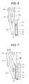
- the links 50A and 50B are let lie idle (refer to FIG. 6 ) and the pressing members 49 are separated from the inner surface of the vertical pipe portion 70. Pressurized air is supplied from the blower 44 into the floating bodies 25, 28, 29, and 30 and the buoyancy is increased.
- the movable body 2 ascends in the vertical pipe portion 70 and ascends to another preventive maintenance execution position.
- this preventive maintenance execution position as aforementioned, the buoyancy of the floating bodies 25, 28, 29, and 30 is adjusted and the ascent of the movable body 2 is stopped. Thereafter, as aforementioned, the movable body 2 is held on the inner surface of the vertical pipe portion 70 by the clamp apparatuses 48A and 48B.
- the high-pressure water containing cavitation bubbles is jetted from the jet nozzles 4A and 4B and at the position, the water jet peening is executed all over the periphery of the inner surface of the vertical pipe portion 70.
- the air in the floating bodies 25, 28, 29, and 30 is discharged out from the air hose 46.
- the buoyancy by the floating bodies 25, 28, 29, and 30 is reduced, thus the movable body 2 descends in the vertical pipe portion 70.
- the inner surface of the vertical pipe portion 70 for which the preventive maintenance operation is performed is photographed by the camera 64 during the descent of the movable body 2 and the image is displayed on the aforementioned monitor. An execution state of the preventive maintenance operation in the inner surface of the vertical pipe portion can be inspected by seeing the image displayed on the monitor.
- pressurized air is supplied into the floating bodies 25, 28, 29, and 30 in the horizontal pipe portion 68 and the buoyancy of the movable body 2 is increased.
- the high-pressure hose 18, the air hoses 45 and 60, and the cable are pulled more, thus the movable body 2 is pulled out from the horizontal pipe portion 68 to the cooling water 72 in the reactor pressure vessel 66.
- the movable body 2 pulled out ascends toward the liquid surface of the cooling water 72 by the buoyancy of each floating body.
- the movable body 2 rising to the liquid surface of the cooling water 72 is collected from the inside of the cooling water 72.
- the movable body 2 of the preventive maintenance apparatus 1 has a plurality of floating bodies such as the floating bodies 25, 26, 27, 28, 29, and 30, so that the preventive maintenance operation for the inner surface of the pipe 67 connected to the reactor pressure vessel 66 with the cooling water 72 filled, and including the horizontal pipe portion 68, the curve pipe portion 69, and the vertical pipe portion 70 can be easily executed.
- the movable body 2 can be easily inserted into the pipe 67 through the opening which is formed at the lower edge of the pipe 67 and is released into the reactor pressure vessel 66. As a result, the preventive maintenance operation for the inner surface of the pipe 67 can be executed.
- the present embodiment has the buoyancy adjusting apparatus, so that the air pressure in each inside of the floating bodies 25, 26, 27, 28, 29 and 30 can be easily adjusted, thus the movement of the movable body 2 in the pipe 67 can be easily controlled.
- the air pressure in the floating bodies 25 and 30 is increased by the buoyancy adjusting apparatus and the buoyancy acting on the leading portion of the movable body 2 is increased. Consequently, the insertion of the movable body 2 into the curve pipe portion 69 and the movement thereof in the curve pipe portion 69 can be performed smoothly.
- the ascent velocity of the movable body 2 in the vertical pipe portion 70 can be adjusted and the movable body 2 can be stopped at the preventive maintenance operation position in the vertical pipe portion 70.
- the motor (the nozzle rotation unit) 7 is installed in the movable body 2, so that the jet nozzles 4A and 4B can be rotated along the inner surface of the pipe 67 in the pipe 67 and the residual compression stress can be given all over the periphery of the inner surface.
- the valves 20 and 24 are switched to on or off, thus the high-pressure water discharged from the high-pressure pump 17 can be supplied to the jet nozzle 22 when driving the movable body 2 and to the jet nozzles 4A and 4B when executing the water jet peening for the inner surface of the pipe 67. Since the high-pressure pump 17 can be shared by the water jet peening apparatus 3 and the driving apparatus 21, the constitution of the preventive maintenance apparatus 1 can be simplified.
- a head for ultrasonic test or a head for eddy current test is attached to the base body 62 in place of the cavitation generator 4, thus the preventive maintenance apparatus 1 can be used as non destructive examination equipment for performing a non destructive examination for the inner surface of the pipe 67.
- preventive maintenance apparatus 2 movable body 3 : water jet peening apparatus 4A, 4B, 22 : jet nozzle 4 : cavitation generator 5 : rotary shaft 7, 14 : motor 13 : nozzle movable unit 17 : high-pressure pump 21 : driving apparatus 25, 26, 27, 28, 29, 30 : floating body 38, 39, 40, 41, 42, 43, 47 : valve 44, 59: blower 48A, 48B : clamp apparatus 61 : control board 62 : base body 63A, 63B : camera unit 66 : reactor pressure vessel 67 : pipe 68 : horizontal pipe portion 69 : curve pipe portion 70: vertical pipe portion 71 : air supply apparatus.
Landscapes
- Engineering & Computer Science (AREA)
- General Engineering & Computer Science (AREA)
- Chemical & Material Sciences (AREA)
- Combustion & Propulsion (AREA)
- Mechanical Engineering (AREA)
- Physics & Mathematics (AREA)
- Plasma & Fusion (AREA)
- High Energy & Nuclear Physics (AREA)
- Monitoring And Testing Of Nuclear Reactors (AREA)
Applications Claiming Priority (1)
| Application Number | Priority Date | Filing Date | Title |
|---|---|---|---|
| JP2011252375A JP5778555B2 (ja) | 2011-11-18 | 2011-11-18 | 予防保全装置および配管内面の予防保全方法 |
Publications (1)
| Publication Number | Publication Date |
|---|---|
| EP2595156A2 true EP2595156A2 (fr) | 2013-05-22 |
Family
ID=47358537
Family Applications (1)
| Application Number | Title | Priority Date | Filing Date |
|---|---|---|---|
| EP12193050.7A Withdrawn EP2595156A2 (fr) | 2011-11-18 | 2012-11-16 | Appareil de maintenance préventive et procédé d'entretien préventif pour la surface intérieure de canalisations |
Country Status (3)
| Country | Link |
|---|---|
| US (1) | US20130125929A1 (fr) |
| EP (1) | EP2595156A2 (fr) |
| JP (1) | JP5778555B2 (fr) |
Cited By (1)
| Publication number | Priority date | Publication date | Assignee | Title |
|---|---|---|---|---|
| CN115007577A (zh) * | 2022-07-21 | 2022-09-06 | 上海先予工业自动化设备有限公司 | 一种电动汽车电池零件清洗机 |
Families Citing this family (8)
| Publication number | Priority date | Publication date | Assignee | Title |
|---|---|---|---|---|
| JP6129583B2 (ja) * | 2013-02-27 | 2017-05-17 | 三菱重工業株式会社 | ウォータジェットピーニング装置 |
| CN105455381B (zh) * | 2014-08-22 | 2019-08-20 | 建福实业有限公司 | 一种卷发器及其使用方法 |
| US10375901B2 (en) | 2014-12-09 | 2019-08-13 | Mtd Products Inc | Blower/vacuum |
| JP2016125610A (ja) * | 2015-01-06 | 2016-07-11 | 株式会社東芝 | 管内移動装置 |
| US10257471B2 (en) * | 2015-01-23 | 2019-04-09 | Envirosight Llc | Steerable nozzle-mounted camera system and method |
| US10769684B1 (en) * | 2017-10-03 | 2020-09-08 | Wells Fargo Bank, N.A. | Property assessment system with buoyancy adjust device |
| CN109524136B (zh) * | 2018-11-22 | 2022-05-20 | 西南石油大学 | 一种高能管断裂甩击行为的试验装置及方法 |
| US11931779B2 (en) * | 2021-02-11 | 2024-03-19 | Saudi Arabian Oil Company | Smart scraper |
Citations (3)
| Publication number | Priority date | Publication date | Assignee | Title |
|---|---|---|---|---|
| JPH085773A (ja) | 1994-06-20 | 1996-01-12 | Toshiba Corp | ジェットポンプの予防保全装置と予防保全方法 |
| JP2001264482A (ja) | 2000-03-23 | 2001-09-26 | Toshiba Corp | 配管の内面検査装置 |
| JP2008014447A (ja) | 2006-07-07 | 2008-01-24 | Hitachi Ltd | 配管内作業装置 |
Family Cites Families (9)
| Publication number | Priority date | Publication date | Assignee | Title |
|---|---|---|---|---|
| US4934179A (en) * | 1988-08-17 | 1990-06-19 | Biggerstaff Bruce A | Pipe inspection method and device |
| JP2692735B2 (ja) * | 1995-07-04 | 1997-12-17 | 株式会社東京久栄 | 管路内清掃装置 |
| JP3990006B2 (ja) * | 1997-07-09 | 2007-10-10 | バブコック日立株式会社 | 管体端部の水噴流施工装置及び水噴流施工方法 |
| JP3806246B2 (ja) * | 1998-06-19 | 2006-08-09 | 三菱重工業株式会社 | 検査ツール搬送装置 |
| JP3590947B2 (ja) * | 1999-08-18 | 2004-11-17 | 株式会社スギノマシン | 管路内水中清掃装置 |
| JP2001159696A (ja) * | 1999-12-03 | 2001-06-12 | Toshiba Corp | ジェットポンプの検査補修方法および装置 |
| JP4901543B2 (ja) * | 2007-03-23 | 2012-03-21 | 株式会社東芝 | 配管内作業装置および配管内作業方法 |
| JP2009090443A (ja) * | 2007-10-12 | 2009-04-30 | Toshiba Plant Systems & Services Corp | 表面改質装置およびその改質方法 |
| CA2723555C (fr) * | 2008-05-07 | 2017-09-05 | Hydrascan Limited | Appareil de nettoyage de conduit |
-
2011
- 2011-11-18 JP JP2011252375A patent/JP5778555B2/ja not_active Expired - Fee Related
-
2012
- 2012-11-15 US US13/678,069 patent/US20130125929A1/en not_active Abandoned
- 2012-11-16 EP EP12193050.7A patent/EP2595156A2/fr not_active Withdrawn
Patent Citations (3)
| Publication number | Priority date | Publication date | Assignee | Title |
|---|---|---|---|---|
| JPH085773A (ja) | 1994-06-20 | 1996-01-12 | Toshiba Corp | ジェットポンプの予防保全装置と予防保全方法 |
| JP2001264482A (ja) | 2000-03-23 | 2001-09-26 | Toshiba Corp | 配管の内面検査装置 |
| JP2008014447A (ja) | 2006-07-07 | 2008-01-24 | Hitachi Ltd | 配管内作業装置 |
Cited By (2)
| Publication number | Priority date | Publication date | Assignee | Title |
|---|---|---|---|---|
| CN115007577A (zh) * | 2022-07-21 | 2022-09-06 | 上海先予工业自动化设备有限公司 | 一种电动汽车电池零件清洗机 |
| CN115007577B (zh) * | 2022-07-21 | 2023-09-22 | 上海先予工业自动化设备有限公司 | 一种电动汽车电池零件清洗机 |
Also Published As
| Publication number | Publication date |
|---|---|
| US20130125929A1 (en) | 2013-05-23 |
| JP5778555B2 (ja) | 2015-09-16 |
| JP2013108780A (ja) | 2013-06-06 |
Similar Documents
| Publication | Publication Date | Title |
|---|---|---|
| US20130125929A1 (en) | Preventive Maintenance Apparatus and Preventive Maintenance Method for Inner Surface of Piping | |
| US7303360B2 (en) | Underwater inspecting and repairing system | |
| US20080223106A1 (en) | Tip tool guide apparatus and method for bringing in tip tool guide apparatus | |
| JP5997761B2 (ja) | 水中ロボット式ベント及び検査システム | |
| JP2006313152A (ja) | 浸漬ボアの中へツールを送り出す装置 | |
| US8687758B2 (en) | Method for managing internal equipment in reactor pressure vessel and apparatus thereof | |
| KR100983920B1 (ko) | 자동 침투 탐상 검사 장치 | |
| JP2003337192A (ja) | 原子炉圧力容器内構造物の点検予防保全装置および点検方法 | |
| EP2610038B1 (fr) | Elément de serrage, dispositif de fonctionnement en chambre d'équilibre, et procédé de serrage | |
| JP2010078433A (ja) | 遠隔作業装置 | |
| US20130170597A1 (en) | Preventive maintenance/repair device and preventive mainenance/repair method for cylindrical structure | |
| JPH0915377A (ja) | 遠隔炉内作業装置および方法 | |
| JP7389196B2 (ja) | 往復移動装置 | |
| CN104992737B (zh) | Cepr核电站控制棒驱动机构的焊缝超声检查装置 | |
| KR100713954B1 (ko) | 원자로 헤드에 설치된 관통관의 노즐 및 관통관 용접부위의검사시스템 | |
| CN105225707B (zh) | 一种核电站水下带吸盘的浮游装置 | |
| KR20150099812A (ko) | 워터젯 피닝 장치 및 워터젯 피닝 시공 방법 | |
| US20150013413A1 (en) | Water Jet Peening Apparatus and Water Jet Peening Method | |
| JP2004298991A (ja) | 構造物表面の補修検査システム | |
| KR200438808Y1 (ko) | 원자로 용기 하부 관통관 검사장치 | |
| JP4262450B2 (ja) | 原子炉狭隘部の補修システム | |
| JP5956360B2 (ja) | ウォータージェットピーニング方法 | |
| RU172466U1 (ru) | Ремонтный аппарат, обеспечивающий оперативный ремонт трубопровода для доставки углеводородного сырья | |
| JP2002040186A (ja) | 原子炉配管内点検装置 | |
| KR100680482B1 (ko) | 원자력발전소의 원자로헤드 노즐 검사장치 |
Legal Events
| Date | Code | Title | Description |
|---|---|---|---|
| PUAI | Public reference made under article 153(3) epc to a published international application that has entered the european phase |
Free format text: ORIGINAL CODE: 0009012 |
|
| 17P | Request for examination filed |
Effective date: 20130215 |
|
| AK | Designated contracting states |
Kind code of ref document: A2 Designated state(s): AL AT BE BG CH CY CZ DE DK EE ES FI FR GB GR HR HU IE IS IT LI LT LU LV MC MK MT NL NO PL PT RO RS SE SI SK SM TR |
|
| AX | Request for extension of the european patent |
Extension state: BA ME |
|
| STAA | Information on the status of an ep patent application or granted ep patent |
Free format text: STATUS: THE APPLICATION HAS BEEN WITHDRAWN |
|
| 18W | Application withdrawn |
Effective date: 20151126 |