EP2595162B1 - Drahtlose Leistungsübertragungsvorrichtung - Google Patents
Drahtlose Leistungsübertragungsvorrichtung Download PDFInfo
- Publication number
- EP2595162B1 EP2595162B1 EP12191671.2A EP12191671A EP2595162B1 EP 2595162 B1 EP2595162 B1 EP 2595162B1 EP 12191671 A EP12191671 A EP 12191671A EP 2595162 B1 EP2595162 B1 EP 2595162B1
- Authority
- EP
- European Patent Office
- Prior art keywords
- power
- coil
- transmitting
- power transmitting
- power receiving
- Prior art date
- Legal status (The legal status is an assumption and is not a legal conclusion. Google has not performed a legal analysis and makes no representation as to the accuracy of the status listed.)
- Active
Links
Images






Classifications
-
- H—ELECTRICITY
- H01—ELECTRIC ELEMENTS
- H01F—MAGNETS; INDUCTANCES; TRANSFORMERS; SELECTION OF MATERIALS FOR THEIR MAGNETIC PROPERTIES
- H01F27/00—Details of transformers or inductances, in general
- H01F27/28—Coils; Windings; Conductive connections
- H01F27/2871—Pancake coils
-
- H—ELECTRICITY
- H01—ELECTRIC ELEMENTS
- H01F—MAGNETS; INDUCTANCES; TRANSFORMERS; SELECTION OF MATERIALS FOR THEIR MAGNETIC PROPERTIES
- H01F38/00—Adaptations of transformers or inductances for specific applications or functions
- H01F38/14—Inductive couplings
-
- H—ELECTRICITY
- H02—GENERATION; CONVERSION OR DISTRIBUTION OF ELECTRIC POWER
- H02J—ELECTRIC POWER NETWORKS; CIRCUIT ARRANGEMENTS OR SYSTEMS FOR SUPPLYING OR DISTRIBUTING ELECTRIC POWER; SYSTEMS FOR STORING ELECTRIC ENERGY
- H02J50/00—Circuit arrangements or systems for wireless supply or distribution of electric power
- H02J50/005—Mechanical details of housing or structure aiming to accommodate the power transfer means, e.g. mechanical integration of coils, antennas or transducers into emitting or receiving devices
-
- H—ELECTRICITY
- H02—GENERATION; CONVERSION OR DISTRIBUTION OF ELECTRIC POWER
- H02J—ELECTRIC POWER NETWORKS; CIRCUIT ARRANGEMENTS OR SYSTEMS FOR SUPPLYING OR DISTRIBUTING ELECTRIC POWER; SYSTEMS FOR STORING ELECTRIC ENERGY
- H02J50/00—Circuit arrangements or systems for wireless supply or distribution of electric power
- H02J50/40—Circuit arrangements or systems for wireless supply or distribution of electric power using two or more transmitting or receiving devices
Definitions
- the present disclosure relates to a wireless power transmitting apparatus wirelessly transmitting a power using a power transmitting coil.
- US 2004/267,501 A1 is directed to a maintenance unit wherein a sensor apparatus includes a battery and a substantially planar secondary coil that includes at least one coil turn, the secondary coil being connected with the battery for charging the battery, the power charger further comprising a substantially planar primary coil having at least two coil turns, at least one of the at least two coil turns being wound in a clockwise direction, at least one of the at least two coil turns being wound in a counter clockwise direction; whereby, placing the secondary coil in a substantially parallel non-coplanar position proximal to the primary coil causes an induction of electrical power in the secondary coil when electrical power is applied to the primary coil.
- various portable terminals such as a cellular phone, a personal digital assistant (PDA), and the like, have been mounted with a power receiving apparatus such as a battery pack charged with a power to supply an operation power thereto.
- the power receiving apparatus may be charged with a power supplied from an external charging apparatus and supply the charged power to the portable terminal to operate the portable terminal.
- the power receiving apparatus may include a battery cell module charged with the power, a charging and discharging circuit charging the power supplied from the external charging apparatus in the battery cell module and discharging the power charged in the battery cell module to supply the discharged power to the portable terminal, and the like.
- the terminal of the charging apparatus and the terminal of the power receiving apparatus have the different potential difference. Therefore, in the case in which the terminal of the charging apparatus and the terminal of the power receiving apparatus are connected to each other or disconnected from each other, an instantaneous discharging phenomenon may occur.
- the instantaneous discharge phenomenon causes abrasion of the terminal of the charging apparatus and the terminal of the power receiving apparatus.
- heat is generated from the foreign materials, such that there is a risk of an accident such as a fire, or the like.
- the power charged in the battery cell module of the power receiving apparatus is naturally discharged to the outside through the terminal of the power receiving apparatus due to moisture, or the like, such that a lifespan of the power receiving apparatus may be decreased and performance of the power receiving apparatus may be deteriorated.
- the wireless power transmitting apparatus wirelessly transmits the power in, for example, an electromagnetic induction scheme.
- the power receiving apparatus receives the power wirelessly transmitted by the wireless power transmitting apparatus and charges the received power in the battery cell module.
- the wireless power transmitting apparatus includes a core assembly.
- the core assembly of the wireless power transmitting apparatus includes a core and a power transmitting coil seated on the core and transmitting the power.
- the power receiving apparatus also includes a core assembly, and the core assembly of the power receiving apparatus includes a core and a power receiving coil seated on the core and receiving the power transmitted by the wireless power transmitting apparatus.
- the power transmitting coil included in the core assembly of the wireless power transmitting apparatus and the power receiving coil included in the core assembly of the power receiving apparatus have different sizes due to characteristics thereof.
- a size of the power receiving coil is determined according to a size of the power receiving apparatus.
- the power transmitting coil of the wireless power transmitting apparatus should be able to be mounted with the entire portable terminal in which the power receiving apparatus is mounted. Therefore, there is a limitation that a size of the power transmitting coil of the wireless power transmitting apparatus should be larger than that of the portable terminal.
- the portable terminal since the portable terminal generally has a rectangular shape, the power transmitting coil included in the core assembly of the wireless power transmitting apparatus generally an oval shape or a rectangular shape rather than a circular shape, and the core included in the core assembly of the wireless power transmitting apparatus also has a rectangular shape or an oval shape rather than a square shape.
- the power receiving apparatus mounted in the portable terminal generally has a square shape
- the power receiving coil included in the core assembly of the power receiving apparatus generally has a circular shape
- the core on which the power receiving coil is mounted also generally has a rectangular shape or a circular shape.
- the unbalance of the sizes of the core assemblies provided in each of the wireless power transmitting apparatus and the power receiving apparatus causes unbalance of the power received by the power receiving apparatus. That is, in the case in which the power receiving apparatus is put on the wireless power transmitting apparatus, a power induced to the power receiving coil of the core assembly of the power receiving apparatus by a magnetic flux generated by a current flowing to the power transmitting coil of the core assembly of the wireless power transmitting apparatus is changed according to a position at which the core assembly of the power receiving apparatus is put.
- the unbalance of the power induced to the power receiving coil has a negative effect on communication of digital data transmitted between the wireless power transmitting apparatus and the power receiving apparatus.
- An object of the present disclosure is to provide a power transmitting coil and a wireless power transmitting apparatus capable of transmitting a power from a core assembly of the wireless power transmitting apparatus to a core assembly of a power receiving apparatus in an optimal state regardless of a position at which the core assembly of the power receiving apparatus is put on the core assembly of the wireless power transmitting apparatus.
- Another object of the present disclosure is to provide a power transmitting coil and a wireless power transmitting apparatus capable of increasing a degree of freedom in a position at which a core assembly of a power receiving apparatus is put on a core assembly of the wireless power transmitting apparatus.
- a power transmitting coil including: at least one first coil having a current flowing in a first direction in the case of transmitting a power; and at least one second coil disposed at an outer side of the first coil and having a current flowing in a second direction opposite to the first direction in the case of transmitting the power.
- a wireless power transmitting apparatus including: a power transmitting unit switching a direct current (DC) power to generate an alternate current (AC) power; and a core assembly wirelessly transmitting the AC power generated by the power transmitting unit, wherein the core assembly includes: a power transmitting coil having the AC power applied thereto; and a core receiving the power transmitting coil therein, the power transmitting coil including: at least one first coil having a current flowing in a first direction in the case of transmitting a power; and at least one second coil disposed at an outer side of the first coil and having a current flowing in a second direction opposite to the first direction in the case of transmitting the power.
- the power transmitting unit may include: a power transmission controlling unit controlling power transmission; a driving driver generating a driving signal for the power transmission under the control of the power transmission controlling unit; and a series resonant converter switching the DC power according to the driving signal generated by the driving driver to supply the AC power to the power transmitting coil.
- a wireless power transmitting apparatus including: a power transmitting unit switching a DC power to generate an AC power; a core assembly including a power transmitting coil wirelessly transmitting the AC power generated by the power transmitting unit and a core receiving the power transmitting coil therein; and a switching unit provided between the power transmitting unit and the power transmitting coil of the core assembly and switching the AC power under a control of a power transmission controlling unit of the power transmitting unit, wherein the power transmitting coil includes: at least one first coil having a current flowing in a first direction in the case of transmitting a power; and at least one second coil disposed at an outer side of the first coil and having a current flowing in a second direction opposite to the first direction in the case of transmitting the power, and wherein the switching unit switches the AC power under the control of the power transmission controlling unit to selectively supply the switched power to the first coil and the second coil.
- the power transmitting unit may include: in addition to the power transmission controlling unit controlling power transmission and controlling a switching operation of the switching unit; a driving driver generating a driving signal for the power transmission under the control of the power transmission controlling unit; and a series resonant converter switching the DC power according to the driving signal generated by the driving driver to output the switched power to the switching unit.
- the power transmitting unit may further include: a signal transmitting unit generating a request signal requesting information on a power receiving apparatus under the control of the power transmission controlling unit and transmitting the generated request signal to the power receiving apparatus through the power transmitting coil; and a signal receiving unit receiving a signal from the power receiving apparatus through the power transmitting coil and providing the received signals to the power transmission controlling unit.
- the series resonant converter may selectively supply the AC power to the first coil and the second coil according to a position at which a power receiving coil of a power receiving apparatus is put on the power transmitting coil.
- the power transmission controlling unit is arranged to control the switching unit according to a position at which a power receiving coil of a power receiving apparatus is put on the power transmitting coil to selectively supply the AC power to the first coil and the second coil.
- a straight line distance between inner and outer peripheral surfaces resulting from the sum of the first coil and the second coil may be larger than a diameter of a power receiving coil wirelessly receiving the power.
- the first coil and the second coil are wound in directions opposite to each other.
- the first coil and the second coil may be consecutively wound using one wire coated with an insulating material.
- the first coil and the second coil may be individually wound using a wire coated with an insulating material and be electrically connected in series with each other by soldering an outer end portion of the first coil and an inner end portion of the second coil to each other.
- the first coil and the second coil are disposed in a concentric circle arrangement on the same plane.
- FIGS. 1A and 1B are diagrams for describing an operation of transmitting a power from a power transmitting coil of a core assembly of a wireless power transmitting apparatus to a power receiving coil of a core assembly of a power receiving apparatus.
- reference numeral 100 indicates a power transmitting coil included in a core assembly of a wireless power transmitting apparatus to transmit a power
- reference numeral 110 indicates a power receiving coil included in a core assembly of a power receiving apparatus to receive the power.
- the power transmitting coil 100 and the power receiving coil 110 which are formed by winding wires coated with an insulating material in a clockwise direction (or a counterclockwise direction), have different forms.
- the power transmitting coil 100 generally has a significantly larger size as compared with the power receiving coil 110, due to characteristics thereof.
- the power transmitting coil 100 has an oval shape and has a horizontal width of about 57 mm and a vertical width of about 70 mm in FIG. 1
- the power receiving coil 110 has a circular shape and a diameter of an outer peripheral edge of about 32 mm.
- a top current I TxTop flowing in a region at a top position when viewed in FIG. 1A a right current I TxRight flowing in a region at a right position when viewed in FIG. 1A , a bottom current I TxBottom flowing in a region at a bottom position when viewed in FIG. 1A , and a left current I TxLeft flowing in a region at a left position when viewed in FIG. 1A flow to the power transmitting coil 100 in a first direction, for example, a clockwise direction, such that magnetic fluxes are generated.
- a first direction for example, a clockwise direction
- the magnetic fluxes generated in the power transmitting coil 100 are interlinked with the power receiving coil 110, such that a top current I RxTop flowing in a region at a top position when viewed in FIG. 1B , a right current I RxRight flowing in a region at a right position when viewed in FIG. 1B , a bottom current I RxBottom flowing in a region at a bottom position when viewed in FIG. 1B , and a left current I RxLeft flowing in a region at a left position when viewed in FIG. 1B flow to the power receiving coil 110 in the clockwise direction, as shown in FIG. 1B .
- the power transmitting coil 100 and the power receiving coil 110 may be entirely linked to each other so that the magnetic field interlinkage is smoothly made, and the power receiving coil 110 may receive the power in an optimal state.
- a user may not accurately put the power receiving coil 110 of the power receiving apparatus at the central position of the power transmitting coil 100.
- a vibration is generated in a portable terminal having the power receiving apparatus mounted therein to move the portable terminal, such that the power receiving coil 110 of the power receiving apparatus may deviate from the central position of the power transmitting coil 100.
- the power transmitting coil 100 and the power receiving coil 110 are linked to each other so that magnetic flux interlinkages of the top current I TxTop flowing to the power transmitting coil 100 and the bottom current I RxBottom flowing to the power receiving coil 110 are offset against each other, and the power induced to the power receiving coil 110 becomes relatively smaller than the power in the case shown in FIG. 2A .
- the power transmitting coil 100 and the power receiving coil 110 are linked to each other so that so that magnetic flux interlinkages of the bottom current I TxBottom flowing to the power transmitting coil 100 and the top current I RxTop flowing to the power receiving coil 110 are offset against each other, and the power induced to the power receiving coil 110 becomes relatively smaller than the power in the case shown in FIG. 2A .
- strength of the power from the power transmitting coil 100 to the power receiving coil 110 is changed according to the position of the power receiving coil 110, such that a degree of freedom in the position at which the power receiving coil 110 is put on the power transmitting coil 100 is significantly limited, which needs to be improved.
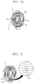
- FIG. 3 is a diagram showing a configuration of a power transmitting coil not being covered by the scope of the claims but that is useful for understanding the disclosure.
- reference numeral 200 indicates a first coil seated on a central portion of a core (not shown).
- the first coil 200 which is wound in a first direction, for example, a counterclockwise direction, has a current flowing in the first direction in the case of transmitting the power.
- Reference numeral 210 indicates a second coil seated on the core and positioned at an outer side of the first coil 200.
- the second coil 210 is wound in a second direction, for example, a clockwise direction, opposite to the first direction.
- the second coil 210 may be connected in series with the first coil 200 as shown in a partially enlarged view of FIG. 3 and has a current flowing in the second direction, for example, the clockwise direction, opposite to the direction in which the current flows in the first coil 200 in the case of transmitting the power.
- the power transmitting coil may be manufactured by consecutively winding the first coil 200 and the second coil 210 using one wire coated with an insulating material to connect the first coil 200 and the second coil 210 in series with each other.
- the power transmitting coil may be manufactured by individually winding the first coil 200 and the second coil 210, overturning any one of the first coils 200 and the second coil 210, and soldering 230 an outer end portion of the first coil 200 and an inner end portion of the second coil 210 to each other to connect the first coil 200 and the second coil 210 in series with each other.
- the power transmitting coil may be manufactured by appropriately setting a predetermined dedicated winding machine according to a work condition and performing a series of winding processes using the predetermined dedicated winding machine or winding the first coil and winding the second coil in a changed direction. Since a specific manufacturing method of the power transmitting coil is not relevant to the intention of the present disclosure, a detailed description thereof will be omitted.
- a straight line distance between inner and outer peripheral surfaces resulting from the sum of the first coil 200 and the second coil 210 is larger than a diameter of the power receiving coil included in the power receiving apparatus.
- an alternate current (AC) power is applied to the first coil 200 and the second coil 210.
- the first coil 200 has the current flowing in the first direction, for example, the counterclockwise direction to transmit the power to the power receiving coil.
- the second coil 210 has the current flowing in the second direction, for example, the clockwise direction, opposite to the first direction to transmit the power to the power receiving coil.
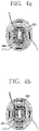
- FIGS. 4A to 4C are diagrams for describing a current inducted and flowing to a power receiving coil according to a position at which the power receiving coil is put on the power transmitting coil of the example not being covered by the scope of the claims but that is useful for understanding the present disclosure.
- the power receiving coil 220 is put on the central portion of the power transmitting coil including the first coil 200 and the second coil 210, the power receiving coil 220 is positioned on the first coil 200.
- the first coil 200 and the power receiving coil 220 may be entirely linked to each other so that magnetic field interlinkage is smoothly made, and the power receiving coil 220 may receive the power in an optimal state.
- the bottom of the power receiving coil 220 is positioned on the top of the first coil 200, and the top thereof is positioned on the top of the second coil 210.
- the second and first coils 210 and 200 and the power receiving coil 220 are linked to each other so that magnetic flux interlinkages of the top currents I TxTop each flowing to the second coil 210 and the first coil 200 and the top current I RxTop and the bottom current I RxBottom of the power receiving coil 220 coincide with other. Therefore, the power receiving coil 220 may receive the power in an optimal state even though the power is relatively slightly smaller as compared with the case shown in FIG. 4A .
- the top of the power receiving coil 220 is positioned on the bottom of the first coil 200, and the bottom thereof is positioned on the bottom of the second coil 210.
- directions of the top current I TxTop and the bottom current I TxBottom flowing to the first coil 200 and directions of the top current I RxTop and the bottom current I RxBottom induced and flowing to the power receiving coil 220 coincide with one another.
- the first and second coils 200 and 210 and the power receiving coil 220 are linked to each other so that magnetic flux interlinkages of the bottom current I TxBottom of the first coil 200 and the second coil 210 and the top current I RxTop and the bottom current I RxBottom of the power receiving coil 220 coincide with other. Therefore, the power receiving coil 220 may receive the power in an optimal state even though the power is relatively slightly smaller as compared with the case shown in FIG. 4A .
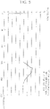
- a graph as shown in FIG. 5 was obtained based on the result obtained by measuring voltage gain-frequency response characteristics according to the position at which the power receiving coil 220 is put on the first coil 200 and the second coil 210 of the power transmitting coil according to the example not being covered by the scope of the claims but useful for understanding the present disclosure.
- a position of the power receiving coil 220 used in the experiment is based on the top position of the power transmitting coil as shown in FIG. 4B , the bottom position of the power transmitting coil as shown in FIG. 4C , and the central position of the power transmitting coil as shown in FIG. 4A .
- a change in a resonance frequency according to the position at which the power receiving coil 220 is put on the power transmitting coil was small, and a change range of a voltage gain according to the position at which the power receiving coil 220 is put on the power transmitting coil was 1 dB or less, which is significantly smaller than that of the power transmitting coil according to the related art.
- a change range of a mutual inductance is relatively significantly small due to the small change range of the voltage gain.
- a first power transmitting coil 310 and a second power transmitting coil 320 may also be provided on one core 300.
- the first power transmitting coil 310 and the second power transmitting coil 320 may include first coils 312 and 322 wound in a first direction and second coils 314 and 324 seated at outer sides of the first coils 312 and 322 and wound in a second direction opposite to the first direction, respectively.
- a first power transmitting coil 410, a second power transmitting coil 420, and a third power transmitting coil 430 may also be provided on one core 400.
- the first power transmitting coil 410 the second power transmitting coil 420, and the third power transmitting coil 430 may include first coils 412, 422, and 432 wound in a first direction and second coils 414, 424, and 434 seated at outer sides of the first coils 412, 422, and 432 and wound in a second direction opposite to the first direction, respectively.
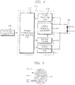
- FIG. 8 is a circuit diagram showing a configuration of a wireless power transmitting apparatus of an example not being covered by the scope of the claims but that is useful for understanding the present disclosure. Since configuration examples of circuit diagrams according to the structures of the power transmitting coils corresponding to the cases of FIGS. 3 , 6 and 7 and modified examples thereof may be easily modified and executed by those skilled in the art with reference to the following description of FIG. 8 , a detailed description thereof will be omitted.
- the wireless power transmitting apparatus of FIG. 8 using one power transmitting coil will be representatively described in order to assist in understanding the present disclosure.
- the wireless power transmitting apparatus of the example not being covered by the scope of the claims is configured to include an alternate current (AC) to a direct current (DC) converter 500 converting a commercial AC power input from the outside into a DC power, a power transmitting unit 510 supplying a power to be wirelessly transmitted, and a core assembly 520 wirelessly transmitting the power.
- AC alternate current
- DC direct current
- the AC to DC converter 500 may also be separately provided at an outer side of the wireless power transmitting apparatus according to an example not being covered by the scope of the claims but useful for understanding the present disclosure to supply the DC power to the power transmitting unit 510, in executing the present disclosure.
- the power transmitting unit 510 switches the DC power converted by the AC to DC converter 500 and supplies the switched power to a first coil 521 and a second coil 523 included in the core assembly 520 to allow the power to be wirelessly transmitted.
- the power transmitting unit 510 may include a power transmission controlling unit 511, a driving driver 513, a series resonant converter 515, a signal transmitting unit 517, and a signal receiving unit 519.
- the power transmission controlling unit 511 controls that the power is wirelessly transmitted through the first coil 521 and the second coil 523 of the core assembly 520.
- the driving driver 513 generates a driving signal for transmitting the power through the first coil 521 and the second coil 523 of the core assembly 520 under the control of the power transmission controlling unit 511.
- the series resonant converter 515 switches the DC power output by the AC to DC converter 500 according to the driving signal generated by the driving driver 513 and supplies the switched power to the first coil 521 and the second coil 523.
- the signal transmitting unit 517 generates a request signal requesting information on a power receiving apparatus under the control of the power transmission controlling unit 511 and transmits the generated request signal to the power receiving apparatus through the first coil 521 and the second coil 523.
- the signal receiving unit 519 receives an information signal, a charging state signal, and the like, transmitted by the power receiving apparatus through the first coil 521 and the second coil 523 and provides the received signals to the power transmission controlling unit 511.
- the wireless power transmitting apparatus In the case in which the wireless power transmitting apparatus according to the example not being covered by the scope of the claims but useful for understanding the present disclosure having the above-mentioned configuration transmits the power, it should first judge whether or not a power receiving unit of the power receiving apparatus may receive the power. That is, the wireless power transmitting apparatus should judge whether or not the power receiving unit of the power receiving apparatus is positioned at a position of the core assembly 520 included in the wireless power transmitting apparatus.
- the power transmission controlling unit 511 of the power transmitting unit 510 controls the driving driver 513 to generate the driving signal for detecting a change in a load.
- the driving signal generated by the driving driver 513 is input to the series resonant converter 515.
- the series resonant converter 515 which includes a plurality of switching devices such as a plurality of transistors, a plurality of metal oxide semiconductor field effect transistors (MOSFETs), or the like, selectively switches the plurality of switching devices according to the driving signal generated by the driving driver 513 to switch a DC power, thereby generating an AC power.
- a plurality of switching devices such as a plurality of transistors, a plurality of metal oxide semiconductor field effect transistors (MOSFETs), or the like.
- the AC power generated by the series resonant converter 515 is output to the first coil 521 and the second coil 523 of the core assembly 520, and the first coil 521 and the second coil 523 are series-resonated by the AC power generated by the series resonant converter 515.
- the signal receiving unit 519 receives signals of the first coil 521 and the second coil 523 and outputs the received signals to the power transmission controlling unit 511.
- the power transmission controlling unit 511 receives the signal of the signal receiving unit 519 and judges whether or not a change in a load has been generated in the first coil 521 and the second coil 523 of the core assembly 520 using the received signal.
- the signal receiving unit 519 may receive only a signal having a frequency according to the driving signal generated by the driving driver 513, and the power transmission controlling unit 511 may judge that the change in the load has not been generated in the first coil 521 and the second coil 523 using the signal of the signal receiving unit 519.
- the change in the impedance is generated in the first coil 521 and the second coil 523.
- the frequency of the signal for detecting the change in the load, applied to the first coil 521 and the second coil 523 is changed according to the change in the impedance.
- the signal receiving unit 519 may receive the signal having the frequency changed according to the change in the impedance, and the power transmission controlling unit 511 judges that the change in the load has been generated in the first coil 521 and the second coil 523 using the signal of the signal receiving unit 519.
- the power transmission controlling unit 511 controls the signal transmitting unit 517 to generate the request signal requesting the information on the power receiving apparatus, for example, a request signal requesting an identification (ID) of the power receiving apparatus, and the generated request signal is transmitted to the power receiving apparatus through the first coil 521 and the second coil 523.
- ID an identification
- the power transmission controlling unit 511 receives the signal of the signal receiving unit 519 to judge whether or not an ID signal of the power receiving apparatus has been received.
- the change in the impedance is generated in the first coil 521 and the second coil 523 due to several causes.
- the change in the impedance may be generated.
- foreign materials other than the power receiving apparatus approach the first coil 521 and the second coil 523
- the change in the impedance may be generated.
- the power transmission controlling unit 511 transmits the request signal request the ID to the power receiving apparatus in the case in which it is judged that the change in the load has been generated in the first coil 521 and the second coil 523 and judges that the impedance has been changed in the first coil 521 and the second coil 523 by the power receiving apparatus in the case in which the ID signal is received from the power receiving apparatus according to the request signal.
- the power transmission controlling unit 511 judges that the power receiving apparatus has approached the first coil 521 and the second coil 523 and controls the driving driver 513 to generate the driving signal for transmitting the power.
- the switching devices of the series resonant converter 515 switch the DC power while being switched according to the driving signal generated by the driving driver 513 to generate the AC power and apply the generated AC power to the first coil 521 and the second coil 523, such that the power is wirelessly transmitted from the first coil 521 and the second coil 523 to the power receiving apparatus.
- the power transmission controlling unit 511 receives the signal of the signal receiving unit 519 to judge whether or not a charging completion signal has been received from the power receiving apparatus and controls the driving driver 513 to end the power transmission in the case in which it is judged that the charging completion signal has been received.
- the power transmitting coil according to the example not being covered by the scope of the claims but useful for understanding the present disclosure includes the first coil and the second coil that are connected in series with each other has been described above by way of example.
- the power transmitting coil includes a first coil 600 wound in a first direction and a second coil 610 wound in a second direction opposite to the first direction and is configured so that a power to be transmitted is selectively supplied to each of the first coil 600 and the second coil 610.
- a wireless power transmitting apparatus having the above-mentioned configuration allows the series resonant converter 515 to selectively supply the power the first coil 600 and the second coil 610 according to the position at which the power receiving coil is put on the power transmitting coil.
- the series resonant converter 515 supplies the power only to the first coil 600 to transmit the power to the power receiving apparatus.
- the series resonant converter 515 supplies the power only to the second coil 610 to transmit the power to the power receiving apparatus.
- the series resonant converter 515 supplies the power to both of the first coil 600 and the second coil 610 to transmit the power to the power receiving apparatus.
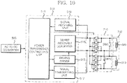
- FIG. 10 is a diagram showing a configuration of a wireless power transmitting apparatus according to an embodiment of the present invention.
- the wireless power transmitting apparatus includes a switching unit 710 disposed between a series resonant converter 515 and a first coil 600 and a second coil 610 that are included in a core assembly 700 and including a plurality of switches SW1 and SW10.
- each of the plurality of switches SW1 to SW10 included in the switching unit 710 is switched under a control of a power transmission controlling unit 511.
- the power transmission controlling unit 511 controls the switching of the plurality of switches SW1 to SW10 included in the switching unit 710 to selectively supply the power to the first coil 600 and the second coil 610, thereby making it possible to wirelessly transmit the power and selectively adjust directions of currents flowing to the first coil 600 and the second coil 610.
- FIGS. 11A to 11D are diagrams for simply describing that a direction in which a current flows to a first coil 600 and a second coil 610 of the power transmitting coil may be selectively changed according to a switching operation of a switching unit in the wireless power transmitting apparatus according to another embodiment of the present invention.
- the power transmission controlling unit 511 controls the switching unit 710 to switch on the switches SW1 and SW4 since the power is supplied only to the first coil 600, the power may be wirelessly transmitted through the first coil 600. Further, in the case the switches SW5 and SW8 are switched on, since the power is supplied only to the second coil 610, the power may be wirelessly transmitted through the second coil 610.
- the power transmission controlling unit 511 controls the switching unit 710 to switch on the switches SW2 and SW3 since the power is supplied only to the first coil 600, the power may be wirelessly transmitted through the first coil 600. Further, in the case the switches SW6 and SW7 are switched on, since the power is supplied only to the second coil 610, the power may be wirelessly transmitted through the second coil 610. In this case, the first coil 600 and the second coil 610 have a current flows in a direction opposite to the current direction in the case of FIG. 11A described above.
- the power transmission controlling unit 511 controls the switching unit 710 to switch on the switches SW1, SW6, and SW10
- the power since the power is supplied to both of the first coil 600 and the second coil 610, the power may be wirelessly transmitted through both of the first coil 600 and the second coil 610.
- currents flow in directions opposite to each other in the first coil 600 and the second coil 610, such that magnetic fluxes are generated in directions opposite to each other.
- the power transmission controlling unit 511 controls the switching unit 710 to switch on the switches SW3, SW8, and SW9
- the power since the power is supplied to both of the first coil 600 and the second coil 610, the power may be wirelessly transmitted through both of the first coil 600 and the second coil 610.
- currents flow in directions opposite to each other in the first coil 600 and the second coil 610, such that magnetic fluxes are generated in directions opposite to each other.
- the power transmitting coil includes the first coil wound in the first direction and the second coil wound in the second direction opposite to the first direction, thereby making it possible to transmit the power in an optimal state regardless of a position at which the power receiving apparatus is positioned on the power transmitting coil. Therefore, a degree of freedom in a position at which the power receiving apparatus charging the power is put may be set to be wide.
- digital data may be smoothly transmitted between the wireless power transmitting apparatus and the power receiving apparatus.
Landscapes
- Engineering & Computer Science (AREA)
- Power Engineering (AREA)
- Computer Networks & Wireless Communication (AREA)
- Charge And Discharge Circuits For Batteries Or The Like (AREA)
Claims (4)
- Drahtlose Leistungsübertragungsvorrichtung, umfassend:eine Leistungsübertragungseinheit (510), die angeordnet ist, um eine DC-Leistung zu schalten, um eine AC-Leistung zu erzeugen;eine Kernbaugruppe, die eine Leistungsübertragungsspule, die angeordnet ist, um die von der Leistungsübertragungseinheit erzeugte AC-Leistung drahtlos zu übertragen, und einen Kern umfasst, der angeordnet ist, um die Leistungsübertragungsspule darin aufzunehmen; undeine Schalteinheit (710), die zwischen der Leistungsübertragungseinheit (510) und der Leistungsübertragungsspule der Kernbaugruppe bereitgestellt ist und angeordnet ist, um die AC-Leistung zu schalten,wobei die Leistungsübertragungsspule beinhaltet:mindestens eine erste Spule (600), die in eine erste Richtung gewickelt ist und so angeordnet ist, dass im Fall des Übertragens einer Leistung ein Strom darin in die erste Richtung fließt; undmindestens eine zweite Spule (610), die in eine zweite Richtung entgegengesetzt zur ersten Richtung gewickelt ist, wobei die zweite Spule (610) an einer Außenseite der ersten Spule (600) vorgesehen und so angeordnet ist, dass im Fall des Übertragens einer Leistung ein Strom darin in die zweite Richtung fließt,wobei:die erste Spule (600) und die zweite Spule (610) in einer konzentrischen Kreisanordnung auf derselben Ebene angeordnet sind;die Leistungsübertragungseinheit (510) eine Leistungsübertragungssteuereinheit (511) beinhaltet, die so angeordnet ist, dass sie die Leistungsübertragung steuert und einen Schaltvorgang der Schalteinheit steuert;die Schalteinheit angeordnet ist, um die AC-Leistung unter einer Steuerung der Leistungsübertragungssteuereinheit (511) zu schalten, um den geschalteten Strom selektiv der ersten Spule und der zweiten Spule zuzuführen und die Richtungen von Strömen, die zu der ersten Spule und der zweite Spule fließen, gemäß einer Position anzupassen, in der eine Leistungsempfangsspule einer Leistungsempfangsvorrichtung auf die Leistungsübertragungsspule gelegt wird;wobei die Leistungsübertragungssteuereinheit (511) angeordnet ist, um die Schalteinheit (710) so zu steuern, dass:die Leistung nur an die erste Spule (600) zugeführt wird, um die Leistung an die Leistungsempfangsvorrichtung zu übertragen, falls die Leistungsempfangsspule nur auf die erste Spule (600) gelegt wird;die Leistung nur an die zweite Spule (600) zugeführt wird, um die Leistung an die Leistungsempfangsvorrichtung zu übertragen, falls die Leistungsempfangsspule nur auf die zweite Spule (610) gelegt wird; unddie Leistung sowohl an die erste Spule (600) also auch die zweite Spule (610) zugeführt wird, um die Leistung an die Leistungsempfangsvorrichtung zu übertragen, falls die Leistungsempfangsspule sowohl auf die erste Spule (600) als auch auf die zweite Spule (610) gelegt wird.
- Drahtlose Leistungsübertragungsvorrichtung nach Anspruch 1, wobei ein geradliniger Abstand zwischen Innen- und Außenumfangsflächen, der sich aus der Summe der ersten Spule und der zweiten Spule ergibt, größer ist als ein Durchmesser einer Leistungsempfangsspule, die die Leistung drahtlos empfängt.
- Drahtlose Leistungsübertragungsvorrichtung nach Anspruch 1 oder Anspruch 2, wobei die Leistungsübertragungseinheit (510) beinhaltet:einen Antriebstreiber (513), der angeordnet ist, um ein Antriebssignal für die Leistungsübertragung unter der Steuerung der Leistungsübertragungssteuereinheit (511) zu erzeugen; undeinen Reihenresonanzwandler (515), der so angeordnet ist, dass er die DC-Leistung gemäß dem durch den Antriebstreiber (513) erzeugten Antriebssignal schaltet, um die geschaltete Leistung an die Schalteinheit auszugeben.
- Drahtlose Leistungsübertragungsvorrichtung nach Anspruch 3, wobei die Leistungsübertragungseinheit (510) ferner beinhaltet:eine Signalübertragungseinheit (517), die so angeordnet ist, dass sie ein Anforderungssignal erzeugt, das Informationen über eine Leistungsempfangsvorrichtung unter der Steuerung der Leistungsübertragungssteuereinheit (511) anfordert, und das erzeugte Anforderungssignal durch die Leistungsübertragungsspule an die Leistungsempfangsvorrichtung überträgt; undeine Signalempfangseinheit (519), die so angeordnet ist, dass sie ein Signal von der Leistungsempfangsvorrichtung durch die Leistungsübertragungsspule empfängt und die empfangenen Signale an die Leistungsübertragungssteuereinheit (511) bereitstellt.
Priority Applications (1)
| Application Number | Priority Date | Filing Date | Title |
|---|---|---|---|
| EP22172360.4A EP4092701A1 (de) | 2011-11-10 | 2012-11-07 | Vorrichtung zur drahtlosen stromübertragung |
Applications Claiming Priority (1)
| Application Number | Priority Date | Filing Date | Title |
|---|---|---|---|
| KR1020110116929A KR101356623B1 (ko) | 2011-11-10 | 2011-11-10 | 전력전송코일 및 무선 전력전송장치 |
Related Child Applications (1)
| Application Number | Title | Priority Date | Filing Date |
|---|---|---|---|
| EP22172360.4A Division EP4092701A1 (de) | 2011-11-10 | 2012-11-07 | Vorrichtung zur drahtlosen stromübertragung |
Publications (3)
| Publication Number | Publication Date |
|---|---|
| EP2595162A2 EP2595162A2 (de) | 2013-05-22 |
| EP2595162A3 EP2595162A3 (de) | 2017-08-30 |
| EP2595162B1 true EP2595162B1 (de) | 2022-05-11 |
Family
ID=47522244
Family Applications (2)
| Application Number | Title | Priority Date | Filing Date |
|---|---|---|---|
| EP22172360.4A Pending EP4092701A1 (de) | 2011-11-10 | 2012-11-07 | Vorrichtung zur drahtlosen stromübertragung |
| EP12191671.2A Active EP2595162B1 (de) | 2011-11-10 | 2012-11-07 | Drahtlose Leistungsübertragungsvorrichtung |
Family Applications Before (1)
| Application Number | Title | Priority Date | Filing Date |
|---|---|---|---|
| EP22172360.4A Pending EP4092701A1 (de) | 2011-11-10 | 2012-11-07 | Vorrichtung zur drahtlosen stromübertragung |
Country Status (5)
| Country | Link |
|---|---|
| US (1) | US9472336B2 (de) |
| EP (2) | EP4092701A1 (de) |
| JP (1) | JP6140428B2 (de) |
| KR (1) | KR101356623B1 (de) |
| CN (1) | CN103107008B (de) |
Families Citing this family (40)
| Publication number | Priority date | Publication date | Assignee | Title |
|---|---|---|---|---|
| GB0716679D0 (en) * | 2007-08-28 | 2007-10-03 | Fells J | Inductive power supply |
| JP5748628B2 (ja) * | 2011-09-28 | 2015-07-15 | 株式会社アドバンテスト | ワイヤレス受電装置およびワイヤレス給電装置 |
| US9548621B2 (en) | 2012-05-28 | 2017-01-17 | Panasonic Intellectual Property Management Co., Ltd. | Contactless connector system tolerant of position displacement between transmitter coil and receiver coil and having high transmission efficiency |
| JP6300106B2 (ja) * | 2013-01-30 | 2018-03-28 | パナソニックIpマネジメント株式会社 | 非接触電力伝送装置 |
| KR101474766B1 (ko) * | 2013-09-05 | 2014-12-22 | 한국과학기술원 | 집전모듈 |
| JP2015053794A (ja) | 2013-09-06 | 2015-03-19 | ローム株式会社 | 位置ずれ検出装置および電子機器 |
| CN104518570A (zh) * | 2013-09-27 | 2015-04-15 | 中兴通讯股份有限公司 | 一种电动车无线电能传输系统的控制方法及装置 |
| JP6156115B2 (ja) * | 2013-12-13 | 2017-07-05 | トヨタ自動車株式会社 | 送電装置 |
| CN105934863B (zh) | 2014-01-30 | 2019-08-13 | 索尼公司 | 受电设备、受电控制方法、无线供电系统以及电子设备 |
| US10003217B2 (en) * | 2014-03-04 | 2018-06-19 | Qualcomm Incorporated | System and method for reducing emissions for polarized coil systems for wireless inductive power transfer |
| US10461582B2 (en) * | 2014-03-31 | 2019-10-29 | Qualcomm Incorporated | Systems, apparatus, and methods for wireless power receiver coil configuration |
| KR102166881B1 (ko) | 2014-04-03 | 2020-10-16 | 엘지이노텍 주식회사 | 무선 전력 송신 장치 |
| JP2015216828A (ja) * | 2014-04-24 | 2015-12-03 | パナソニック株式会社 | 異物検出装置、無線送電装置、及び無線電力伝送システム |
| JP6617213B2 (ja) * | 2014-04-24 | 2019-12-11 | パナソニック株式会社 | 異物検出装置、無線送電装置、及び無線電力伝送システム |
| JP6378006B2 (ja) * | 2014-08-29 | 2018-08-22 | 東芝テック株式会社 | 電力伝送装置及び送電装置 |
| US9780572B2 (en) * | 2014-10-27 | 2017-10-03 | Qualcomm Incorporated | Wireless power multi-coil mutual induction cancellation methods and apparatus |
| KR101719040B1 (ko) * | 2014-11-13 | 2017-03-23 | 현대자동차주식회사 | 무선 충전 시스템 |
| US9698608B2 (en) | 2014-12-29 | 2017-07-04 | Qualcomm Incorporated | System and method for multi-coil dual backbone dynamic inductive power transfer |
| KR20160100754A (ko) * | 2015-02-16 | 2016-08-24 | 엘지이노텍 주식회사 | 무선 전력 수신 장치 및 방법 |
| KR101736160B1 (ko) | 2015-03-18 | 2017-05-16 | 서울과학기술대학교 산학협력단 | 하나의 동일평면상에 공진코일과 공진루프를 평면화시킨 스마트 2d형 자기공진 무선전력송수신장치 |
| US9312701B1 (en) * | 2015-07-16 | 2016-04-12 | Wi-Charge Ltd | System for optical wireless power supply |
| JP6520567B2 (ja) * | 2015-08-25 | 2019-05-29 | 船井電機株式会社 | 給電装置 |
| CN105118644A (zh) * | 2015-09-30 | 2015-12-02 | 武汉大学 | 适用于电动汽车无线供电系统的增强型发射线圈 |
| CN105262241A (zh) * | 2015-09-30 | 2016-01-20 | 武汉大学 | 适用于电动汽车无线供电系统的发射线圈 |
| CN105162226B (zh) * | 2015-09-30 | 2018-02-09 | 武汉大学 | 基于增强型发射线圈的电动汽车动态无线供电系统及方法 |
| KR102453528B1 (ko) * | 2015-10-14 | 2022-10-13 | 삼성디스플레이 주식회사 | 전자기 유도 패널, 이를 포함하는 전자기 유도 장치 및 이를 포함하는 표시 장치 |
| CN105449668B (zh) * | 2015-11-23 | 2019-04-02 | 江苏省电力公司南通供电公司 | 智能变电站电能质量监测智能电子设备的动态建模方法 |
| US20170155285A1 (en) * | 2015-11-30 | 2017-06-01 | Electronics And Telecommunications Research Institute | Open type resonance coil without dual loops having serial type in-phase direct power feeding method without dual loops |
| CN105515158B (zh) * | 2015-12-15 | 2018-10-30 | 深圳市航天新源科技有限公司 | 一种高可靠卫星电源控制器数字控制系统 |
| KR101804410B1 (ko) * | 2015-12-17 | 2017-12-04 | 엘지이노텍 주식회사 | 무선 전력 송신기를 위한 송신 코일 모듈 |
| KR20170126735A (ko) | 2016-05-10 | 2017-11-20 | 삼성전자주식회사 | 자기 스트라이프 데이터 전송 장치 및 방법 |
| CN107370243B (zh) * | 2017-06-20 | 2019-06-07 | 华为技术有限公司 | 一种终端无线充电接收装置、发射装置与无线充电系统 |
| KR102154240B1 (ko) | 2017-07-06 | 2020-09-09 | 한국전자통신연구원 | 일정한 피치를 가지는 수신 코일을 포함하는 무선 전력 전송 시스템 |
| KR102661233B1 (ko) * | 2018-01-26 | 2024-04-25 | 인디고 테크놀로지스, 인크. | 통합형 임피던스 매칭을 갖는 무선 전력 전송 시스템 및 그 사용 방법 |
| JP6587720B2 (ja) * | 2018-07-20 | 2019-10-09 | 東芝テック株式会社 | 電力伝送装置及び送電装置 |
| US20220123593A1 (en) * | 2019-02-15 | 2022-04-21 | Xnergy Autonomous Power Technologies Pte. Ltd. | Wireless Power Transfer Based on Magnetic Induction |
| KR102085010B1 (ko) | 2019-02-26 | 2020-03-05 | 광주과학기술원 | 무선전력전송 시스템용 형상 설계 시스템 및 방법 |
| EP3795408A1 (de) * | 2019-09-23 | 2021-03-24 | Ningbo Geely Automobile Research & Development Co. Ltd. | Vorrichtung für ein system zur drahtlosen stromübertragung zum laden eines fahrzeugs |
| CN114313316B (zh) * | 2021-12-16 | 2023-09-15 | 深圳市航天新源科技有限公司 | 一种电源控制器分组冷备数字控制系统 |
| CN114425956B (zh) * | 2022-03-08 | 2024-04-16 | 哈尔滨工业大学(威海) | 一种用于无人机充电的磁耦合充电设备以及系统 |
Family Cites Families (23)
| Publication number | Priority date | Publication date | Assignee | Title |
|---|---|---|---|---|
| US6650213B1 (en) * | 2000-06-02 | 2003-11-18 | Yamatake Corporation | Electromagnetic-induction coupling apparatus |
| US7282889B2 (en) * | 2001-04-19 | 2007-10-16 | Onwafer Technologies, Inc. | Maintenance unit for a sensor apparatus |
| EP1506605A2 (de) * | 2002-05-13 | 2005-02-16 | Splashplower Limited | Berührungslose leistungsübertragung |
| AU2003282214A1 (en) * | 2002-10-28 | 2004-05-13 | Splashpower Limited | Unit and system for contactless power transfer |
| JP2004229406A (ja) * | 2003-01-23 | 2004-08-12 | Sony Corp | 分離トランス装置 |
| US6934167B2 (en) * | 2003-05-01 | 2005-08-23 | Delta Electronics, Inc. | Contactless electrical energy transmission system having a primary side current feedback control and soft-switched secondary side rectifier |
| TWI268429B (en) * | 2003-11-29 | 2006-12-11 | Onwafer Technologies Inc | Systems, maintenance units and substrate processing systems for wirelessly charging and wirelessly communicating with sensor apparatus as well as methods for wirelessly charging and communicating with sensor apparatus |
| DE502005003976D1 (de) * | 2005-03-24 | 2008-06-19 | Siemens Ag | Induktiver Drehübertrager |
| KR100819604B1 (ko) * | 2005-07-27 | 2008-04-03 | 엘에스전선 주식회사 | 충전효율의 편차가 개선된 무선 충전기 |
| KR100792308B1 (ko) * | 2006-01-31 | 2008-01-07 | 엘에스전선 주식회사 | 코일 어레이를 구비한 무접점 충전장치, 무접점 충전시스템 및 충전 방법 |
| KR101390746B1 (ko) * | 2006-08-04 | 2014-05-02 | 에스케이케미칼주식회사 | 비접촉식 충전 및 데이터 전송용 유도코일 |
| GB0716679D0 (en) * | 2007-08-28 | 2007-10-03 | Fells J | Inductive power supply |
| WO2009114671A1 (en) * | 2008-03-13 | 2009-09-17 | Access Business Group International Llc | Inductive power supply system with multiple coil primary |
| ES2556269T3 (es) * | 2008-04-03 | 2016-01-14 | Koninklijke Philips N.V. | Sistema inalámbrico de transmisión de energía |
| US8229567B2 (en) * | 2008-04-30 | 2012-07-24 | Medtronic, Inc. | Concentric primary coils for inductively charging an implantable medical device, external power source and method |
| CN101828320B (zh) * | 2008-12-12 | 2013-04-10 | 郑春吉 | 非接触充电站、非接触受电装置及其控制方法 |
| EP2357716B1 (de) * | 2008-12-12 | 2017-08-30 | Intel Corporation | Kontaktlose kraftübertragungsvorrichtung |
| CA2757623A1 (en) * | 2009-04-08 | 2010-10-14 | Access Business Group International Llc | Selectable coil array |
| JP2011142559A (ja) * | 2010-01-08 | 2011-07-21 | Sony Corp | 給電装置、受電装置、およびワイヤレス給電システム |
| JP5139469B2 (ja) * | 2010-04-27 | 2013-02-06 | 株式会社日本自動車部品総合研究所 | コイルユニットおよび非接触給電システム |
| JP5532422B2 (ja) * | 2010-07-30 | 2014-06-25 | スミダコーポレーション株式会社 | コイル |
| EP2428969B1 (de) * | 2010-08-09 | 2016-10-19 | Parspour, Nejila | Spulenanordnung für eine induktive Ladevorrichtung |
| TWI563765B (en) * | 2011-04-08 | 2016-12-21 | Access Business Group Int Llc | Counter wound inductive power supply and related method of manufacture and operation |
-
2011
- 2011-11-10 KR KR1020110116929A patent/KR101356623B1/ko active Active
-
2012
- 2012-11-07 EP EP22172360.4A patent/EP4092701A1/de active Pending
- 2012-11-07 EP EP12191671.2A patent/EP2595162B1/de active Active
- 2012-11-08 CN CN201210444389.XA patent/CN103107008B/zh active Active
- 2012-11-12 JP JP2012248725A patent/JP6140428B2/ja active Active
- 2012-11-13 US US13/675,632 patent/US9472336B2/en active Active
Also Published As
| Publication number | Publication date |
|---|---|
| KR20130051659A (ko) | 2013-05-21 |
| CN103107008B (zh) | 2017-08-01 |
| EP4092701A1 (de) | 2022-11-23 |
| US20130119779A1 (en) | 2013-05-16 |
| JP2013106045A (ja) | 2013-05-30 |
| US9472336B2 (en) | 2016-10-18 |
| EP2595162A3 (de) | 2017-08-30 |
| CN103107008A (zh) | 2013-05-15 |
| EP2595162A2 (de) | 2013-05-22 |
| JP6140428B2 (ja) | 2017-05-31 |
| KR101356623B1 (ko) | 2014-02-03 |
Similar Documents
| Publication | Publication Date | Title |
|---|---|---|
| EP2595162B1 (de) | Drahtlose Leistungsübertragungsvorrichtung | |
| US11005299B2 (en) | Wireless power transmitter and receiver for vehicle | |
| KR101228556B1 (ko) | 무선 전력 전송 장치에서의 전력 전송 코일 선택 제어 방법, 이를 적용한 무선 전력 전송 장치, 및 이를 적용하는 무선 전력 전송 시스템 | |
| US9608697B2 (en) | Wireless power transmitting apparatus and method thereof | |
| JP6633857B2 (ja) | 送電装置および無線電力伝送システム | |
| US20120098486A1 (en) | Non-contact charging station with planar spiral power transmission coil and method for controlling the same | |
| JP6283155B2 (ja) | 無線電力送信アセンブリにおける電力制御方法及び無線電力送信アセンブリ | |
| EP3282539B1 (de) | Stromübertragungsvorrichtung, mit stromübertragungsvorrichtung ausgestattetes fahrzeug und system zur drahtlosen stromübertragung | |
| EP2683054B1 (de) | Drahtloses System mit mehreren Ladegeräten und Steuerverfahren dafür | |
| EP2357715B1 (de) | Kontaktlose ladestation mit einem ptps-kern und einer planaren spiralkernstruktur, kontaktlose stromempfangsvorrichtung und verfahren zu ihrer steuerung | |
| US9318780B2 (en) | Wirelessly rechargeable battery and power transmitter | |
| EP3016231B1 (de) | Kraftübertragungsvorrichtung, fahrzeug mit kraftübertragungsvorrichtung und drahtloses kraftübertragungssystem | |
| US20160248272A1 (en) | Non-contact power reception apparatus for non-contact charging and electronic settlement performed in a single portable terminal | |
| EP3355083A1 (de) | Fremdkörpererkennungsvorrichtung, drahtlose stromübertragungsvorrichtung und drahtloses stromübertragungssystem | |
| JP6551853B2 (ja) | 送電装置、送電装置を搭載した車両及び無線電力伝送システム | |
| CN102457109A (zh) | 控制无线输电设备中无线电力信号的方法及无线输电设备 | |
| JPWO2011135722A1 (ja) | 受電装置及び受電方法 | |
| US20120161540A1 (en) | Apparatus for transmitting/receiving energy in energy system | |
| JP2016039644A (ja) | 送電装置および無線電力伝送システム | |
| US8981713B2 (en) | Charging apparatus using pad type electrode contact point | |
| KR101222777B1 (ko) | 무선 충전용 코일 구조체 및 이를 구비한 무선 충전 장치 | |
| KR20150112160A (ko) | 무선전력전송 송신 장치를 구비한 무선전력전송 시스템 | |
| JP7117219B2 (ja) | 無線給電装置およびこれを用いた多軸ロボット |
Legal Events
| Date | Code | Title | Description |
|---|---|---|---|
| PUAI | Public reference made under article 153(3) epc to a published international application that has entered the european phase |
Free format text: ORIGINAL CODE: 0009012 |
|
| AK | Designated contracting states |
Kind code of ref document: A2 Designated state(s): AL AT BE BG CH CY CZ DE DK EE ES FI FR GB GR HR HU IE IS IT LI LT LU LV MC MK MT NL NO PL PT RO RS SE SI SK SM TR |
|
| AX | Request for extension of the european patent |
Extension state: BA ME |
|
| PUAL | Search report despatched |
Free format text: ORIGINAL CODE: 0009013 |
|
| AK | Designated contracting states |
Kind code of ref document: A3 Designated state(s): AL AT BE BG CH CY CZ DE DK EE ES FI FR GB GR HR HU IE IS IT LI LT LU LV MC MK MT NL NO PL PT RO RS SE SI SK SM TR |
|
| AX | Request for extension of the european patent |
Extension state: BA ME |
|
| RIC1 | Information provided on ipc code assigned before grant |
Ipc: H01F 27/28 20060101ALI20170724BHEP Ipc: H01F 38/14 20060101AFI20170724BHEP |
|
| RAP1 | Party data changed (applicant data changed or rights of an application transferred) |
Owner name: GE HYBRID TECHNOLOGIES, LLC |
|
| STAA | Information on the status of an ep patent application or granted ep patent |
Free format text: STATUS: REQUEST FOR EXAMINATION WAS MADE |
|
| 17P | Request for examination filed |
Effective date: 20180228 |
|
| RAX | Requested extension states of the european patent have changed |
Extension state: BA Payment date: 20180228 Extension state: ME Payment date: 20180228 |
|
| RBV | Designated contracting states (corrected) |
Designated state(s): AL AT BE BG CH CY CZ DE DK EE ES FI FR GB GR HR HU IE IS IT LI LT LU LV MC MK MT NL NO PL PT RO RS SE SI SK SM TR |
|
| STAA | Information on the status of an ep patent application or granted ep patent |
Free format text: STATUS: EXAMINATION IS IN PROGRESS |
|
| 17Q | First examination report despatched |
Effective date: 20200731 |
|
| GRAP | Despatch of communication of intention to grant a patent |
Free format text: ORIGINAL CODE: EPIDOSNIGR1 |
|
| STAA | Information on the status of an ep patent application or granted ep patent |
Free format text: STATUS: GRANT OF PATENT IS INTENDED |
|
| INTG | Intention to grant announced |
Effective date: 20210716 |
|
| GRAJ | Information related to disapproval of communication of intention to grant by the applicant or resumption of examination proceedings by the epo deleted |
Free format text: ORIGINAL CODE: EPIDOSDIGR1 |
|
| STAA | Information on the status of an ep patent application or granted ep patent |
Free format text: STATUS: EXAMINATION IS IN PROGRESS |
|
| INTC | Intention to grant announced (deleted) | ||
| GRAP | Despatch of communication of intention to grant a patent |
Free format text: ORIGINAL CODE: EPIDOSNIGR1 |
|
| STAA | Information on the status of an ep patent application or granted ep patent |
Free format text: STATUS: GRANT OF PATENT IS INTENDED |
|
| INTG | Intention to grant announced |
Effective date: 20220210 |
|
| GRAS | Grant fee paid |
Free format text: ORIGINAL CODE: EPIDOSNIGR3 |
|
| GRAA | (expected) grant |
Free format text: ORIGINAL CODE: 0009210 |
|
| STAA | Information on the status of an ep patent application or granted ep patent |
Free format text: STATUS: THE PATENT HAS BEEN GRANTED |
|
| AK | Designated contracting states |
Kind code of ref document: B1 Designated state(s): AL AT BE BG CH CY CZ DE DK EE ES FI FR GB GR HR HU IE IS IT LI LT LU LV MC MK MT NL NO PL PT RO RS SE SI SK SM TR |
|
| REG | Reference to a national code |
Ref country code: GB Ref legal event code: FG4D |
|
| REG | Reference to a national code |
Ref country code: CH Ref legal event code: EP |
|
| REG | Reference to a national code |
Ref country code: AT Ref legal event code: REF Ref document number: 1492160 Country of ref document: AT Kind code of ref document: T Effective date: 20220515 |
|
| REG | Reference to a national code |
Ref country code: DE Ref legal event code: R096 Ref document number: 602012078196 Country of ref document: DE |
|
| REG | Reference to a national code |
Ref country code: IE Ref legal event code: FG4D |
|
| REG | Reference to a national code |
Ref country code: LT Ref legal event code: MG9D |
|
| REG | Reference to a national code |
Ref country code: NL Ref legal event code: MP Effective date: 20220511 |
|
| REG | Reference to a national code |
Ref country code: AT Ref legal event code: MK05 Ref document number: 1492160 Country of ref document: AT Kind code of ref document: T Effective date: 20220511 |
|
| PG25 | Lapsed in a contracting state [announced via postgrant information from national office to epo] |
Ref country code: SE Free format text: LAPSE BECAUSE OF FAILURE TO SUBMIT A TRANSLATION OF THE DESCRIPTION OR TO PAY THE FEE WITHIN THE PRESCRIBED TIME-LIMIT Effective date: 20220511 Ref country code: PT Free format text: LAPSE BECAUSE OF FAILURE TO SUBMIT A TRANSLATION OF THE DESCRIPTION OR TO PAY THE FEE WITHIN THE PRESCRIBED TIME-LIMIT Effective date: 20220912 Ref country code: NO Free format text: LAPSE BECAUSE OF FAILURE TO SUBMIT A TRANSLATION OF THE DESCRIPTION OR TO PAY THE FEE WITHIN THE PRESCRIBED TIME-LIMIT Effective date: 20220811 Ref country code: NL Free format text: LAPSE BECAUSE OF FAILURE TO SUBMIT A TRANSLATION OF THE DESCRIPTION OR TO PAY THE FEE WITHIN THE PRESCRIBED TIME-LIMIT Effective date: 20220511 Ref country code: LT Free format text: LAPSE BECAUSE OF FAILURE TO SUBMIT A TRANSLATION OF THE DESCRIPTION OR TO PAY THE FEE WITHIN THE PRESCRIBED TIME-LIMIT Effective date: 20220511 Ref country code: HR Free format text: LAPSE BECAUSE OF FAILURE TO SUBMIT A TRANSLATION OF THE DESCRIPTION OR TO PAY THE FEE WITHIN THE PRESCRIBED TIME-LIMIT Effective date: 20220511 Ref country code: GR Free format text: LAPSE BECAUSE OF FAILURE TO SUBMIT A TRANSLATION OF THE DESCRIPTION OR TO PAY THE FEE WITHIN THE PRESCRIBED TIME-LIMIT Effective date: 20220812 Ref country code: FI Free format text: LAPSE BECAUSE OF FAILURE TO SUBMIT A TRANSLATION OF THE DESCRIPTION OR TO PAY THE FEE WITHIN THE PRESCRIBED TIME-LIMIT Effective date: 20220511 Ref country code: ES Free format text: LAPSE BECAUSE OF FAILURE TO SUBMIT A TRANSLATION OF THE DESCRIPTION OR TO PAY THE FEE WITHIN THE PRESCRIBED TIME-LIMIT Effective date: 20220511 Ref country code: BG Free format text: LAPSE BECAUSE OF FAILURE TO SUBMIT A TRANSLATION OF THE DESCRIPTION OR TO PAY THE FEE WITHIN THE PRESCRIBED TIME-LIMIT Effective date: 20220811 Ref country code: AT Free format text: LAPSE BECAUSE OF FAILURE TO SUBMIT A TRANSLATION OF THE DESCRIPTION OR TO PAY THE FEE WITHIN THE PRESCRIBED TIME-LIMIT Effective date: 20220511 |
|
| PG25 | Lapsed in a contracting state [announced via postgrant information from national office to epo] |
Ref country code: RS Free format text: LAPSE BECAUSE OF FAILURE TO SUBMIT A TRANSLATION OF THE DESCRIPTION OR TO PAY THE FEE WITHIN THE PRESCRIBED TIME-LIMIT Effective date: 20220511 Ref country code: PL Free format text: LAPSE BECAUSE OF FAILURE TO SUBMIT A TRANSLATION OF THE DESCRIPTION OR TO PAY THE FEE WITHIN THE PRESCRIBED TIME-LIMIT Effective date: 20220511 Ref country code: LV Free format text: LAPSE BECAUSE OF FAILURE TO SUBMIT A TRANSLATION OF THE DESCRIPTION OR TO PAY THE FEE WITHIN THE PRESCRIBED TIME-LIMIT Effective date: 20220511 Ref country code: IS Free format text: LAPSE BECAUSE OF FAILURE TO SUBMIT A TRANSLATION OF THE DESCRIPTION OR TO PAY THE FEE WITHIN THE PRESCRIBED TIME-LIMIT Effective date: 20220911 |
|
| PG25 | Lapsed in a contracting state [announced via postgrant information from national office to epo] |
Ref country code: SM Free format text: LAPSE BECAUSE OF FAILURE TO SUBMIT A TRANSLATION OF THE DESCRIPTION OR TO PAY THE FEE WITHIN THE PRESCRIBED TIME-LIMIT Effective date: 20220511 Ref country code: SK Free format text: LAPSE BECAUSE OF FAILURE TO SUBMIT A TRANSLATION OF THE DESCRIPTION OR TO PAY THE FEE WITHIN THE PRESCRIBED TIME-LIMIT Effective date: 20220511 Ref country code: RO Free format text: LAPSE BECAUSE OF FAILURE TO SUBMIT A TRANSLATION OF THE DESCRIPTION OR TO PAY THE FEE WITHIN THE PRESCRIBED TIME-LIMIT Effective date: 20220511 Ref country code: EE Free format text: LAPSE BECAUSE OF FAILURE TO SUBMIT A TRANSLATION OF THE DESCRIPTION OR TO PAY THE FEE WITHIN THE PRESCRIBED TIME-LIMIT Effective date: 20220511 Ref country code: DK Free format text: LAPSE BECAUSE OF FAILURE TO SUBMIT A TRANSLATION OF THE DESCRIPTION OR TO PAY THE FEE WITHIN THE PRESCRIBED TIME-LIMIT Effective date: 20220511 Ref country code: CZ Free format text: LAPSE BECAUSE OF FAILURE TO SUBMIT A TRANSLATION OF THE DESCRIPTION OR TO PAY THE FEE WITHIN THE PRESCRIBED TIME-LIMIT Effective date: 20220511 |
|
| REG | Reference to a national code |
Ref country code: DE Ref legal event code: R097 Ref document number: 602012078196 Country of ref document: DE |
|
| PLBE | No opposition filed within time limit |
Free format text: ORIGINAL CODE: 0009261 |
|
| STAA | Information on the status of an ep patent application or granted ep patent |
Free format text: STATUS: NO OPPOSITION FILED WITHIN TIME LIMIT |
|
| PG25 | Lapsed in a contracting state [announced via postgrant information from national office to epo] |
Ref country code: AL Free format text: LAPSE BECAUSE OF FAILURE TO SUBMIT A TRANSLATION OF THE DESCRIPTION OR TO PAY THE FEE WITHIN THE PRESCRIBED TIME-LIMIT Effective date: 20220511 |
|
| 26N | No opposition filed |
Effective date: 20230214 |
|
| PG25 | Lapsed in a contracting state [announced via postgrant information from national office to epo] |
Ref country code: SI Free format text: LAPSE BECAUSE OF FAILURE TO SUBMIT A TRANSLATION OF THE DESCRIPTION OR TO PAY THE FEE WITHIN THE PRESCRIBED TIME-LIMIT Effective date: 20220511 |
|
| PG25 | Lapsed in a contracting state [announced via postgrant information from national office to epo] |
Ref country code: MC Free format text: LAPSE BECAUSE OF FAILURE TO SUBMIT A TRANSLATION OF THE DESCRIPTION OR TO PAY THE FEE WITHIN THE PRESCRIBED TIME-LIMIT Effective date: 20220511 |
|
| REG | Reference to a national code |
Ref country code: CH Ref legal event code: PL |
|
| P01 | Opt-out of the competence of the unified patent court (upc) registered |
Effective date: 20230528 |
|
| REG | Reference to a national code |
Ref country code: BE Ref legal event code: MM Effective date: 20221130 |
|
| PG25 | Lapsed in a contracting state [announced via postgrant information from national office to epo] |
Ref country code: LI Free format text: LAPSE BECAUSE OF NON-PAYMENT OF DUE FEES Effective date: 20221130 Ref country code: CH Free format text: LAPSE BECAUSE OF NON-PAYMENT OF DUE FEES Effective date: 20221130 |
|
| PG25 | Lapsed in a contracting state [announced via postgrant information from national office to epo] |
Ref country code: LU Free format text: LAPSE BECAUSE OF NON-PAYMENT OF DUE FEES Effective date: 20221107 |
|
| PG25 | Lapsed in a contracting state [announced via postgrant information from national office to epo] |
Ref country code: IE Free format text: LAPSE BECAUSE OF NON-PAYMENT OF DUE FEES Effective date: 20221107 |
|
| PG25 | Lapsed in a contracting state [announced via postgrant information from national office to epo] |
Ref country code: BE Free format text: LAPSE BECAUSE OF NON-PAYMENT OF DUE FEES Effective date: 20221130 |
|
| PG25 | Lapsed in a contracting state [announced via postgrant information from national office to epo] |
Ref country code: HU Free format text: LAPSE BECAUSE OF FAILURE TO SUBMIT A TRANSLATION OF THE DESCRIPTION OR TO PAY THE FEE WITHIN THE PRESCRIBED TIME-LIMIT; INVALID AB INITIO Effective date: 20121107 |
|
| PG25 | Lapsed in a contracting state [announced via postgrant information from national office to epo] |
Ref country code: CY Free format text: LAPSE BECAUSE OF FAILURE TO SUBMIT A TRANSLATION OF THE DESCRIPTION OR TO PAY THE FEE WITHIN THE PRESCRIBED TIME-LIMIT Effective date: 20220511 |
|
| PG25 | Lapsed in a contracting state [announced via postgrant information from national office to epo] |
Ref country code: MK Free format text: LAPSE BECAUSE OF FAILURE TO SUBMIT A TRANSLATION OF THE DESCRIPTION OR TO PAY THE FEE WITHIN THE PRESCRIBED TIME-LIMIT Effective date: 20220511 |
|
| PG25 | Lapsed in a contracting state [announced via postgrant information from national office to epo] |
Ref country code: MT Free format text: LAPSE BECAUSE OF FAILURE TO SUBMIT A TRANSLATION OF THE DESCRIPTION OR TO PAY THE FEE WITHIN THE PRESCRIBED TIME-LIMIT Effective date: 20220511 |
|
| PG25 | Lapsed in a contracting state [announced via postgrant information from national office to epo] |
Ref country code: BG Free format text: LAPSE BECAUSE OF FAILURE TO SUBMIT A TRANSLATION OF THE DESCRIPTION OR TO PAY THE FEE WITHIN THE PRESCRIBED TIME-LIMIT Effective date: 20220511 |
|
| PG25 | Lapsed in a contracting state [announced via postgrant information from national office to epo] |
Ref country code: BG Free format text: LAPSE BECAUSE OF FAILURE TO SUBMIT A TRANSLATION OF THE DESCRIPTION OR TO PAY THE FEE WITHIN THE PRESCRIBED TIME-LIMIT Effective date: 20220511 |
|
| PGFP | Annual fee paid to national office [announced via postgrant information from national office to epo] |
Ref country code: DE Payment date: 20241022 Year of fee payment: 13 |
|
| PGFP | Annual fee paid to national office [announced via postgrant information from national office to epo] |
Ref country code: GB Payment date: 20241023 Year of fee payment: 13 |
|
| PGFP | Annual fee paid to national office [announced via postgrant information from national office to epo] |
Ref country code: FR Payment date: 20241022 Year of fee payment: 13 |
|
| PGFP | Annual fee paid to national office [announced via postgrant information from national office to epo] |
Ref country code: IT Payment date: 20241022 Year of fee payment: 13 |
|
| PG25 | Lapsed in a contracting state [announced via postgrant information from national office to epo] |
Ref country code: TR Free format text: LAPSE BECAUSE OF FAILURE TO SUBMIT A TRANSLATION OF THE DESCRIPTION OR TO PAY THE FEE WITHIN THE PRESCRIBED TIME-LIMIT Effective date: 20220511 |