EP2595251B1 - Ensemble de connecteur - Google Patents
Ensemble de connecteur Download PDFInfo
- Publication number
- EP2595251B1 EP2595251B1 EP11189976.1A EP11189976A EP2595251B1 EP 2595251 B1 EP2595251 B1 EP 2595251B1 EP 11189976 A EP11189976 A EP 11189976A EP 2595251 B1 EP2595251 B1 EP 2595251B1
- Authority
- EP
- European Patent Office
- Prior art keywords
- terminals
- connector
- housing
- locking device
- locking
- Prior art date
- Legal status (The legal status is an assumption and is not a legal conclusion. Google has not performed a legal analysis and makes no representation as to the accuracy of the status listed.)
- Active
Links
Images




Classifications
-
- H—ELECTRICITY
- H01—ELECTRIC ELEMENTS
- H01R—ELECTRICALLY-CONDUCTIVE CONNECTIONS; STRUCTURAL ASSOCIATIONS OF A PLURALITY OF MUTUALLY-INSULATED ELECTRICAL CONNECTING ELEMENTS; COUPLING DEVICES; CURRENT COLLECTORS
- H01R13/00—Details of coupling devices of the kinds covered by groups H01R12/70 or H01R24/00 - H01R33/00
- H01R13/40—Securing contact members in or to a base or case; Insulating of contact members
- H01R13/42—Securing in a demountable manner
- H01R13/436—Securing a plurality of contact members by one locking piece or operation
-
- H—ELECTRICITY
- H01—ELECTRIC ELEMENTS
- H01R—ELECTRICALLY-CONDUCTIVE CONNECTIONS; STRUCTURAL ASSOCIATIONS OF A PLURALITY OF MUTUALLY-INSULATED ELECTRICAL CONNECTING ELEMENTS; COUPLING DEVICES; CURRENT COLLECTORS
- H01R13/00—Details of coupling devices of the kinds covered by groups H01R12/70 or H01R24/00 - H01R33/00
- H01R13/64—Means for preventing incorrect coupling
- H01R13/641—Means for preventing incorrect coupling by indicating incorrect coupling; by indicating correct or full engagement
-
- H—ELECTRICITY
- H01—ELECTRIC ELEMENTS
- H01R—ELECTRICALLY-CONDUCTIVE CONNECTIONS; STRUCTURAL ASSOCIATIONS OF A PLURALITY OF MUTUALLY-INSULATED ELECTRICAL CONNECTING ELEMENTS; COUPLING DEVICES; CURRENT COLLECTORS
- H01R13/00—Details of coupling devices of the kinds covered by groups H01R12/70 or H01R24/00 - H01R33/00
- H01R13/40—Securing contact members in or to a base or case; Insulating of contact members
- H01R13/42—Securing in a demountable manner
- H01R13/436—Securing a plurality of contact members by one locking piece or operation
- H01R13/4364—Insertion of locking piece from the front
-
- H—ELECTRICITY
- H01—ELECTRIC ELEMENTS
- H01R—ELECTRICALLY-CONDUCTIVE CONNECTIONS; STRUCTURAL ASSOCIATIONS OF A PLURALITY OF MUTUALLY-INSULATED ELECTRICAL CONNECTING ELEMENTS; COUPLING DEVICES; CURRENT COLLECTORS
- H01R13/00—Details of coupling devices of the kinds covered by groups H01R12/70 or H01R24/00 - H01R33/00
- H01R13/62—Means for facilitating engagement or disengagement of coupling parts or for holding them in engagement
-
- H—ELECTRICITY
- H01—ELECTRIC ELEMENTS
- H01R—ELECTRICALLY-CONDUCTIVE CONNECTIONS; STRUCTURAL ASSOCIATIONS OF A PLURALITY OF MUTUALLY-INSULATED ELECTRICAL CONNECTING ELEMENTS; COUPLING DEVICES; CURRENT COLLECTORS
- H01R13/00—Details of coupling devices of the kinds covered by groups H01R12/70 or H01R24/00 - H01R33/00
- H01R13/66—Structural association with built-in electrical component
- H01R13/665—Structural association with built-in electrical component with built-in electronic circuit
- H01R13/6691—Structural association with built-in electrical component with built-in electronic circuit with built-in signalling means
-
- H—ELECTRICITY
- H01—ELECTRIC ELEMENTS
- H01R—ELECTRICALLY-CONDUCTIVE CONNECTIONS; STRUCTURAL ASSOCIATIONS OF A PLURALITY OF MUTUALLY-INSULATED ELECTRICAL CONNECTING ELEMENTS; COUPLING DEVICES; CURRENT COLLECTORS
- H01R13/00—Details of coupling devices of the kinds covered by groups H01R12/70 or H01R24/00 - H01R33/00
- H01R13/66—Structural association with built-in electrical component
- H01R13/717—Structural association with built-in electrical component with built-in light source
- H01R13/7175—Light emitting diodes (LEDs)
Definitions
- the invention relates to a connector comprising a least a housing with a least one aperture in which at least two terminals are inserted and at least one locking device.
- the locking device is inserted into an opening of the housing for locking at least one of the terminals in the aperture.
- US 5,607,327 discloses a double locking interconnector with a connector housing.
- a terminal is inserted form the rear side in the connector housing.
- the connector housing has flexible locking pieces for engaging with terminal and thereby prevent the connector from being retracted.
- a front holder is inserted from the front side into the connector housing.
- the front holder has locking protrusions engaging with into a recess of the terminal and thereby double locks the terminal in the connector housing.
- US2009/0023329 A1 discloses an electrical plug connector for connecting a sensor.
- the electrical plug connector has an electronic circuit with a LED for visualizing the switching state of the sensor.
- the housing can be made of a transparent thermoplastic material to which a colour concentrate was added.
- US 4,714,437 discloses an electrical connector for automotive applications.
- the connector has a housing with four tubular apertures extending axially there through. Each of the apertures has a retention abutment for engaging into an annular recess of cylindrical terminal. Opposite of each retention abutment is a finger like retention member.
- the flexible retention members permit inserting the terminals the tubular apertures, as they can be bent away and thereby the peripheral surface of the terminals may pass the retention abutment, until the retention abutments engages into the annular recess.
- the retention members exert a restoring force on the terminals, thereby locking the retention abutments in their respective annular recesses. Subsequent to the insertion of the terminals a locking device is inserted from the front side into the housing, blocking the retentions members and thereby locking the terminals in their respective positions.
- the connector easily can be assembled and the terminals are safely locked in the housing.
- the invention is based on the observation that the analysis of malfunctions of a vehicle or a machine due to connection problems is difficult and time consuming.
- the problem to be solved by the invention is to permit a simple control of the connection provided by the connector and its complementary counterpart without changing the design of the connector, i.e. downward compatibility is required.
- the connector comprises a housing with at least one aperture into which at least two terminals are inserted.
- a locking device may be inserted into an opening of the housing for locking at least one of the terminals in the aperture.
- the locking device comprises at least two contact pads, each contact pad connecting one of the at least two terminals.
- the contact pads are connected with a signaling circuit, for example by electric lines.
- the signaling circuit is supported by the locking device and via the pads connected with the terminals. If the terminals are correctly connected to some line, a voltage between the terminals can be detected and analyzed by the signaling means. If the voltage is within a predetermined range the signaling circuit signals "connection established", for example by powering at least one LED.
- the locking device unifies two functions, namely to lock the terminals in the housing and to provide an information about proper connection of the connector.
- the design of the housing is not or only slightly affected by the signaling circuit and can thus be downward compatible.
- the housing preferably comprises at least one retention member engaging with at least one of the terminals and being blocked from releasing the at least one terminal by the locking device.
- the opening of the housing form a gap, which is complementary to at least a section for example a land of the locking device. At least the section may fill the gap and thereby block the retention member(s) such that they are prevented from releasing the engagement between the terminal(s) and the retention member(s).
- the locking device may be secondary locking fixing at least one primary locking device, for example the retention members, and thereby blocking at least one of the terminals.
- a secondary locking may serve as support and/or "printed circuit board" for the signaling circuit, thereby ensuring safe attachment of the terminals to the housing and safe connection of the connection pads with the terminals.
- the signaling circuit may be introduced into the housing with the locking device. This permits to assemble and test the signaling circuit outside the housing.
- the locking device may comprise a front plate for closing the opening of the housing, a land for locking the terminals and a central body between the front plate and the land.
- the central body may support the connection pads.
- the connection pads are preferably in the proximity of the through holes for connecting the terminals. This permits ensuring a safe connection between the connection pads and the terminals.
- the connection pads may e.g. be located on the terminal facing side of the central body. This can easily be manufactured and permits the locking device to exert via the connection pads a force against the terminals, pressing the terminals in an abutment of the housing and thereby connect and stabilize the terminals in their aperture(s) at the same time.
- connection pads may comprise a conducting elastomer, enhancing the connection between the terminals and the connection pads and at the same time to exert a force by the locking device against the terminals.
- the side of the locking device facing away from the terminals may retain the locking device against the housing.
- the locking device could have at least one rim at at least one of its narrow sides, the rim being inserted into a complementary guide in the contour of the opening of the housing.
- connection pads may comprise a cover of a 'pliant' metal, like tin (Sn) or copper (Cu). Such pliant cover may flow, when pressed against one of the terminal and thus permit to insert the locking device until both terminals are safely connected to the pads.
- a 'pliant' metal like tin (Sn) or copper (Cu).
- connection pads may be spring loaded, for example may the connection pad be formed by a land of a spring.
- the signaling circuit preferably comprises electrical components, which may be positioned on the land for example in a clearance between at least two retention members. This permits a very small connector with integrated signaling circuit for controlling proper connection.
- the signaling circuit may e.g. comprise LEDs for indicating if the voltage between the terminals is in a predefined voltage range.
- the signaling circuit may comprise at least one LED being connected in series with a resistor and/or a Zener diode to the connection pads and thereby to the terminals.
- the connector 1 in figure 1 may have an at least partially transparent housing 10 for engagement with a complementary counterpart (not shown) of the connector 1.
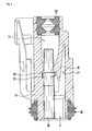
- the connector 1 may have two axially aligned terminals 50 for receiving complementary terminal counterparts (cf. figure 2 , showing a section of the connector in figure 1 along plane III, as indicated in figure 5 ).
- the terminals 50 may be inserted from the rear side 4 into apertures 12 of the housing 10 and may be secured against being retracted by retention members 14, serving as primary locking device.
- Each retention member 14 may engage with an annular thickening 52 of the respective terminal 50.
- the retention members 14 may be flexible and may extend finger like into the opening 11, forming a gap 13 between the wall of the housing and the retention members 14.
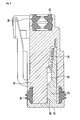
- This gap 13 permits the retention members 14 to pivot when the terminals 50 are inserted from the rear side 4 into their apertures 12 and thus to follow over the peripheral surface of the terminals 50 until they engage with the thickening 52. However, the retention members 14 may still pivot and release the terminals 50, for example if a load is exerted on the terminals 50. Such unwanted release may be avoided by inserting a wedge like locking device 30 like the one depicted in figure 6 into the opening 11 for example from the front side 2. The position of the locking device 30 in the opening 11 and its interaction with the housing 10 is illustrated in the figures 3 and 4 , showing sections of the connector of figure 1 along plane III and plane IV, respectively, as indicated in figure 5 .
- the locking device 30 may be an injection molded part with a front plate 31, a central body 33 and a land 34 (cf. figure 6 ).
- the central body 33 is arranged between the rear side of the front plate 31 and the land 34.
- the front plate 31 may have through holes 32 for pin like terminal members (not shown) of a complementary connector and may close the opening 11 of the housing 10.
- An elastic seal like gasket 94 may be inserted between the front plate 31 and the housing 10 for sealing the connection with the counterpart of the connector 1 and/or the gap between the front plate 31 and the housing 10 and at the same time between the connector 1 and its complementary counterpart.
- the land 34 may have a wedge shape, fitting into the gap 13 between the retention members 14 and the wall of the opening 11, i.e. the housing 10. Thereby, the retention members 14 are inhibited from pivoting and releasing the terminals 50. Thus, the retention members 14 are blocked in engagement with the terminals 50 by the locking device 30, and more particularly by the land 34. Thus, the retention members 14 can be considered as a primary locking of the terminals 50, that are blocked by a secondary locking, namely by the locking device 30.
- the central body 33 of the locking device 30 may have two connection pads 36 for connecting a signaling circuit with the terminals 50 (cf. figure 6 ). Thus, if inserted into the opening 11 of housing 10, each of the connection pads 36 may contact the peripheral surface of one of the terminals 50 (cf. figure 3 ) and thereby connect the signaling circuit with the terminals 50.
- the central body 33 further supports the terminals in their apertures 12.
- the front plate 31 blocks a movement of the terminals 50 in the direction of the front side of the opening. Thus, the terminals 50 are longitudinally blocked between the retention members 14 and the front plate 31.
- An additional forward stop is provided by recesses 15, into which thickenings 52 of the terminals 50 engage.
- the signaling circuit comprises electrical components 35 (cf. figures 4 to 6 ).
- the components may comprise one or more LEDs 35, which may be connected in series by electric lines 37 with at least one resistor 35to the connection pads 36. Additional electronic components may as well be provided, for example as protective element for the at least one LED 35.
- a voltage between the terminals 50 is received by the connection pads 36 and forwarded via the electric lines 37 to the signaling means. If the voltage is in a predefined range, the
- the signaling circuit permits to visually control the proper connection of the connector 1.
- the signaling circuit may as well comprise a microcontroller (not shown), e.g. for controlling establishment of a data bus via the connector or other electrical components. Space for further components is provided by recess 38.
- the position of the electrical components 35 in the housing 11, i.e. after insertion of the locking device 30 into the opening 11, is displayed in figure 4 .
- a clearance 17 (cf. figure 5 , showing a section along plane V) for components like 35 of the signaling circuit.
- the locking device 30 a Molded Interconnection Device, briefly referred to as MID.
- the locking device 30 may as well or as alternative comprise a printed circuit board e.g. for carrying at least the signaling circuit.
- the printed circuit board may be inserted into a recess of wedge.
Landscapes
- Engineering & Computer Science (AREA)
- Microelectronics & Electronic Packaging (AREA)
- Physics & Mathematics (AREA)
- Optics & Photonics (AREA)
- Details Of Connecting Devices For Male And Female Coupling (AREA)
- Connector Housings Or Holding Contact Members (AREA)
Claims (8)
- Connecteur (1), comprenant au moins
un boîtier (10) avec au moins une ouverture (12) ;
au moins deux bornes, chacune étant insérée dans l'une des ouvertures (12), et
au moins un dispositif de verrouillage (30), le dispositif de verrouillage (30) étant inséré dans une ouverture (11) du boîtier (10) pour verrouiller au moins une des bornes (50) dans une ouverture (12) ;
caractérisé en ce que
le dispositif de verrouillage (30) comprend au moins deux plots de contact (36), chaque plot de contact (36) connectant l'une desdites au moins deux bornes (50) ; et
le dispositif de verrouillage (30) supporte un circuit de signalisation, connecté aux plots de contact (36). - Connecteur (1) selon la revendication 1,
caractérisé en ce que
le boîtier (10) est au moins partiellement transparent et en ce que le circuit de signalisation comprend au moins une DEL (35), alimentée lorsque la tension entre les bornes (50) est comprises dans un intervalle prédéfini. - Connecteur (1) selon l'une quelconque des revendications précédentes,
caractérisé en ce que
le boîtier (10) comprend au moins un élément de retenue (14), s'engageant dans au moins une des bornes (50), un dégagement de la borne (50) étant bloqué par le dispositif de verrouillage (30). - Connecteur (1) selon l'une quelconque des revendications précédentes,
caractérisé en ce que
le dispositif de verrouillage (30) comprend une plaque frontale (31) pour fermer l'ouverture (11) du boîtier (1), une partie d'appui (34) pour verrouiller les bornes (50), et un corps central (33) entre la plaque frontale (31) et la partie d'appui (34), le corps central (33) supportant les plots de connexion (36). - Connecteur (1) selon les revendications 3 et 4,
caractérisé en ce que
des composants du circuit de signalisation sont positionnés sur la partie d'appui (34) entre au moins deux éléments de retenue (14). - Connecteur (1) selon l'une quelconque des revendications 4 ou 5,
caractérisé en ce que
les plots de connexion (36) sont agencés sur la borne (50), faisant face au côté du corps central (33). - Connecteur (1) selon l'une quelconque des revendications précédentes,
caractérisé en ce que
les plots de connexion (36) comprennent un élastomère conducteur. - Connecteur (1) selon l'une quelconque des revendications précédentes,
caractérisé en ce que
le dispositif de verrouillage (30) est un verrouillage secondaire pour bloquer la au moins une borne (50) dans le boîtier en fixant un dispositif de verrouillage primaire.
Priority Applications (9)
| Application Number | Priority Date | Filing Date | Title |
|---|---|---|---|
| PL11189976T PL2595251T3 (pl) | 2011-11-21 | 2011-11-21 | Zespół złącza |
| EP11189976.1A EP2595251B1 (fr) | 2011-11-21 | 2011-11-21 | Ensemble de connecteur |
| ES11189976.1T ES2479693T3 (es) | 2011-11-21 | 2011-11-21 | Conjunto de conector |
| BR112014012104-4A BR112014012104B1 (pt) | 2011-11-21 | 2012-11-19 | conector |
| CN201280057214.1A CN103947049B (zh) | 2011-11-21 | 2012-11-19 | 连接器组件 |
| RU2014125281/07A RU2600319C2 (ru) | 2011-11-21 | 2012-11-19 | Соединительный узел |
| KR1020147017069A KR101979923B1 (ko) | 2011-11-21 | 2012-11-19 | 커넥터 조립체 |
| US14/359,526 US9385476B2 (en) | 2011-11-21 | 2012-11-19 | Connector assembly having a locking device with connection pads |
| PCT/EP2012/072997 WO2013076041A1 (fr) | 2011-11-21 | 2012-11-19 | Ensemble connecteur |
Applications Claiming Priority (1)
| Application Number | Priority Date | Filing Date | Title |
|---|---|---|---|
| EP11189976.1A EP2595251B1 (fr) | 2011-11-21 | 2011-11-21 | Ensemble de connecteur |
Publications (2)
| Publication Number | Publication Date |
|---|---|
| EP2595251A1 EP2595251A1 (fr) | 2013-05-22 |
| EP2595251B1 true EP2595251B1 (fr) | 2014-05-07 |
Family
ID=47178747
Family Applications (1)
| Application Number | Title | Priority Date | Filing Date |
|---|---|---|---|
| EP11189976.1A Active EP2595251B1 (fr) | 2011-11-21 | 2011-11-21 | Ensemble de connecteur |
Country Status (9)
| Country | Link |
|---|---|
| US (1) | US9385476B2 (fr) |
| EP (1) | EP2595251B1 (fr) |
| KR (1) | KR101979923B1 (fr) |
| CN (1) | CN103947049B (fr) |
| BR (1) | BR112014012104B1 (fr) |
| ES (1) | ES2479693T3 (fr) |
| PL (1) | PL2595251T3 (fr) |
| RU (1) | RU2600319C2 (fr) |
| WO (1) | WO2013076041A1 (fr) |
Families Citing this family (7)
| Publication number | Priority date | Publication date | Assignee | Title |
|---|---|---|---|---|
| DE102012105256A1 (de) | 2012-06-18 | 2013-12-19 | HARTING Electronics GmbH | Isolierkörper eines Steckverbinders |
| DE102012105257B4 (de) | 2012-06-18 | 2018-06-07 | HARTING Electronics GmbH | Isolierkörper eines Steckverbinders |
| US10249964B1 (en) | 2018-02-12 | 2019-04-02 | Dinkle Enterprise Co., Ltd. | Terminal block |
| EP3528350B1 (fr) * | 2018-02-15 | 2020-06-24 | Dinkle Enterprise Co., Ltd. | Bloc terminal |
| EP3997765A1 (fr) | 2019-07-09 | 2022-05-18 | Valeo Vision | Ensemble de connexion electrique pour module lumineux de vehicule automobile et procede |
| FR3098657B1 (fr) * | 2019-07-09 | 2021-07-09 | Valeo Vision | Ensemble de connexion electrique pour module lumineux de vehicule automobile et procede |
| US12237608B2 (en) * | 2022-06-21 | 2025-02-25 | Aptiv Technologies AG | Electrical connector assembly with flexible and rigid terminal locking features |
Family Cites Families (11)
| Publication number | Priority date | Publication date | Assignee | Title |
|---|---|---|---|---|
| SU920910A1 (ru) * | 1978-03-28 | 1982-04-15 | Специальное Конструкторское Бюро "Спецавтоматика" | Электрический соединительный зажим |
| US4714437A (en) | 1987-01-20 | 1987-12-22 | Ford Motor Company | Electrical connector |
| JP2604378Y2 (ja) * | 1993-12-06 | 2000-05-08 | 矢崎総業株式会社 | フロントホルダ付き二重係止コネクタ |
| JP3758104B2 (ja) * | 1997-05-20 | 2006-03-22 | 矢崎総業株式会社 | コネクタ |
| JP2001110500A (ja) * | 1999-10-05 | 2001-04-20 | Sumitomo Wiring Syst Ltd | コネクタ |
| JP2002260766A (ja) * | 2001-02-27 | 2002-09-13 | Yazaki Corp | コネクタ |
| JP2002313472A (ja) * | 2001-04-16 | 2002-10-25 | Yazaki Corp | コネクタ |
| JP3912253B2 (ja) * | 2002-10-24 | 2007-05-09 | 住友電装株式会社 | コネクタ |
| JP4241352B2 (ja) * | 2003-12-05 | 2009-03-18 | 住友電装株式会社 | コネクタ |
| DE102006006726A1 (de) * | 2006-02-13 | 2007-08-23 | Ifm Electronic Gmbh | Elektrischer Steckverbinder |
| RU2310957C1 (ru) * | 2006-02-26 | 2007-11-20 | Общество с ограниченной ответственностью "Конструкторское Бюро Пожарной Автоматики" | Безвинтовой контактный элемент |
-
2011
- 2011-11-21 EP EP11189976.1A patent/EP2595251B1/fr active Active
- 2011-11-21 ES ES11189976.1T patent/ES2479693T3/es active Active
- 2011-11-21 PL PL11189976T patent/PL2595251T3/pl unknown
-
2012
- 2012-11-19 KR KR1020147017069A patent/KR101979923B1/ko active Active
- 2012-11-19 WO PCT/EP2012/072997 patent/WO2013076041A1/fr not_active Ceased
- 2012-11-19 RU RU2014125281/07A patent/RU2600319C2/ru not_active IP Right Cessation
- 2012-11-19 CN CN201280057214.1A patent/CN103947049B/zh not_active Expired - Fee Related
- 2012-11-19 US US14/359,526 patent/US9385476B2/en active Active
- 2012-11-19 BR BR112014012104-4A patent/BR112014012104B1/pt not_active IP Right Cessation
Also Published As
| Publication number | Publication date |
|---|---|
| RU2600319C2 (ru) | 2016-10-20 |
| BR112014012104B1 (pt) | 2020-12-08 |
| WO2013076041A1 (fr) | 2013-05-30 |
| CN103947049A (zh) | 2014-07-23 |
| BR112014012104A2 (pt) | 2017-06-13 |
| EP2595251A1 (fr) | 2013-05-22 |
| KR20140099286A (ko) | 2014-08-11 |
| CN103947049B (zh) | 2016-08-24 |
| RU2014125281A (ru) | 2015-12-27 |
| KR101979923B1 (ko) | 2019-05-17 |
| ES2479693T3 (es) | 2014-07-24 |
| PL2595251T3 (pl) | 2014-09-30 |
| US9385476B2 (en) | 2016-07-05 |
| US20140335717A1 (en) | 2014-11-13 |
| BR112014012104A8 (pt) | 2017-06-20 |
Similar Documents
| Publication | Publication Date | Title |
|---|---|---|
| US9385476B2 (en) | Connector assembly having a locking device with connection pads | |
| US7632126B1 (en) | High density circular interconnect with bayonet action | |
| CN104362450B (zh) | 具有双向插接功能的插头连接器 | |
| JP6692818B2 (ja) | バスバーを収容するための改良された構造を有する火工式回路遮断器およびその組立方法 | |
| KR101879473B1 (ko) | 에어백 커넥터 시스템 | |
| KR102233071B1 (ko) | 인쇄 회로 기판을 가지는 일회용 전기 커넥터 | |
| US8308501B2 (en) | Solid state lighting assembly having a strain relief member | |
| EP3054534B1 (fr) | Dispositif de commande électronique | |
| TWI547021B (zh) | Electrical connector | |
| KR20110020290A (ko) | 고밀도 사각 인터커넥트 | |
| AU2020260521A1 (en) | Chassis connector | |
| CN110086016B (zh) | 具有主联锁的锁定臂的插塞连接器 | |
| EP4362235A1 (fr) | Ensemble connecteur électrique | |
| JP2012182106A (ja) | 電気コネクタ | |
| CN209748900U (zh) | 用于组装印刷电路板的过压保护器具 | |
| EP3108542B1 (fr) | Connecteur électrique amélioré | |
| US9548575B2 (en) | Device for fixing and electrical contacting a facing element of an aircraft on a support structure | |
| CN109713475B (zh) | 用于使可插接的电器设备与电路板连接的接触元件 | |
| AU2010332814B2 (en) | Connection system for connecting a single-row housing to a terminal element | |
| ES2720139T3 (es) | Dispositivo de instalación eléctrico | |
| US20250308827A1 (en) | Control unit for an electrical circuit breaker and associated electrical circuit breaker | |
| KR200230613Y1 (ko) | 플러그조립체 | |
| JP2008235253A (ja) | スライダー付きコネクタアッセンブリ | |
| KR101842573B1 (ko) | 단자대를 적용한 케이블 연결 및 외부에서 엘이디램프 콘몬설정이 가능한 컨트롤스위치모듈 | |
| KR101865937B1 (ko) | 자동차용 멀티 조인트 커넥터 |
Legal Events
| Date | Code | Title | Description |
|---|---|---|---|
| PUAI | Public reference made under article 153(3) epc to a published international application that has entered the european phase |
Free format text: ORIGINAL CODE: 0009012 |
|
| 17P | Request for examination filed |
Effective date: 20120718 |
|
| AK | Designated contracting states |
Kind code of ref document: A1 Designated state(s): AL AT BE BG CH CY CZ DE DK EE ES FI FR GB GR HR HU IE IS IT LI LT LU LV MC MK MT NL NO PL PT RO RS SE SI SK SM TR |
|
| AX | Request for extension of the european patent |
Extension state: BA ME |
|
| RBV | Designated contracting states (corrected) |
Designated state(s): AL AT BE BG CH CY CZ DE DK EE ES FI FR GB GR HR HU IE IS IT LI LT LU LV MC MK MT NL NO PL PT RO RS SE SI SK SM TR |
|
| RIC1 | Information provided on ipc code assigned before grant |
Ipc: H01R 13/436 20060101AFI20130730BHEP Ipc: H01R 13/641 20060101ALI20130730BHEP Ipc: H01R 13/717 20060101ALN20130730BHEP Ipc: H01R 13/66 20060101ALI20130730BHEP |
|
| GRAP | Despatch of communication of intention to grant a patent |
Free format text: ORIGINAL CODE: EPIDOSNIGR1 |
|
| INTG | Intention to grant announced |
Effective date: 20131205 |
|
| GRAS | Grant fee paid |
Free format text: ORIGINAL CODE: EPIDOSNIGR3 |
|
| GRAA | (expected) grant |
Free format text: ORIGINAL CODE: 0009210 |
|
| AK | Designated contracting states |
Kind code of ref document: B1 Designated state(s): AL AT BE BG CH CY CZ DE DK EE ES FI FR GB GR HR HU IE IS IT LI LT LU LV MC MK MT NL NO PL PT RO RS SE SI SK SM TR |
|
| REG | Reference to a national code |
Ref country code: GB Ref legal event code: FG4D |
|
| REG | Reference to a national code |
Ref country code: AT Ref legal event code: REF Ref document number: 667311 Country of ref document: AT Kind code of ref document: T Effective date: 20140515 |
|
| REG | Reference to a national code |
Ref country code: IE Ref legal event code: FG4D |
|
| REG | Reference to a national code |
Ref country code: DE Ref legal event code: R096 Ref document number: 602011006750 Country of ref document: DE Effective date: 20140618 |
|
| REG | Reference to a national code |
Ref country code: ES Ref legal event code: FG2A Ref document number: 2479693 Country of ref document: ES Kind code of ref document: T3 Effective date: 20140724 |
|
| REG | Reference to a national code |
Ref country code: RO Ref legal event code: EPE |
|
| REG | Reference to a national code |
Ref country code: SE Ref legal event code: TRGR |
|
| REG | Reference to a national code |
Ref country code: PL Ref legal event code: T3 |
|
| REG | Reference to a national code |
Ref country code: SK Ref legal event code: T3 Ref document number: E 16801 Country of ref document: SK |
|
| REG | Reference to a national code |
Ref country code: NL Ref legal event code: VDEP Effective date: 20140507 |
|
| REG | Reference to a national code |
Ref country code: LT Ref legal event code: MG4D |
|
| PG25 | Lapsed in a contracting state [announced via postgrant information from national office to epo] |
Ref country code: NO Free format text: LAPSE BECAUSE OF FAILURE TO SUBMIT A TRANSLATION OF THE DESCRIPTION OR TO PAY THE FEE WITHIN THE PRESCRIBED TIME-LIMIT Effective date: 20140807 Ref country code: CY Free format text: LAPSE BECAUSE OF FAILURE TO SUBMIT A TRANSLATION OF THE DESCRIPTION OR TO PAY THE FEE WITHIN THE PRESCRIBED TIME-LIMIT Effective date: 20140507 Ref country code: GR Free format text: LAPSE BECAUSE OF FAILURE TO SUBMIT A TRANSLATION OF THE DESCRIPTION OR TO PAY THE FEE WITHIN THE PRESCRIBED TIME-LIMIT Effective date: 20140808 Ref country code: LT Free format text: LAPSE BECAUSE OF FAILURE TO SUBMIT A TRANSLATION OF THE DESCRIPTION OR TO PAY THE FEE WITHIN THE PRESCRIBED TIME-LIMIT Effective date: 20140507 Ref country code: FI Free format text: LAPSE BECAUSE OF FAILURE TO SUBMIT A TRANSLATION OF THE DESCRIPTION OR TO PAY THE FEE WITHIN THE PRESCRIBED TIME-LIMIT Effective date: 20140507 Ref country code: IS Free format text: LAPSE BECAUSE OF FAILURE TO SUBMIT A TRANSLATION OF THE DESCRIPTION OR TO PAY THE FEE WITHIN THE PRESCRIBED TIME-LIMIT Effective date: 20140907 |
|
| PG25 | Lapsed in a contracting state [announced via postgrant information from national office to epo] |
Ref country code: LV Free format text: LAPSE BECAUSE OF FAILURE TO SUBMIT A TRANSLATION OF THE DESCRIPTION OR TO PAY THE FEE WITHIN THE PRESCRIBED TIME-LIMIT Effective date: 20140507 Ref country code: HR Free format text: LAPSE BECAUSE OF FAILURE TO SUBMIT A TRANSLATION OF THE DESCRIPTION OR TO PAY THE FEE WITHIN THE PRESCRIBED TIME-LIMIT Effective date: 20140507 Ref country code: RS Free format text: LAPSE BECAUSE OF FAILURE TO SUBMIT A TRANSLATION OF THE DESCRIPTION OR TO PAY THE FEE WITHIN THE PRESCRIBED TIME-LIMIT Effective date: 20140507 |
|
| PG25 | Lapsed in a contracting state [announced via postgrant information from national office to epo] |
Ref country code: PT Free format text: LAPSE BECAUSE OF FAILURE TO SUBMIT A TRANSLATION OF THE DESCRIPTION OR TO PAY THE FEE WITHIN THE PRESCRIBED TIME-LIMIT Effective date: 20140908 |
|
| PG25 | Lapsed in a contracting state [announced via postgrant information from national office to epo] |
Ref country code: DK Free format text: LAPSE BECAUSE OF FAILURE TO SUBMIT A TRANSLATION OF THE DESCRIPTION OR TO PAY THE FEE WITHIN THE PRESCRIBED TIME-LIMIT Effective date: 20140507 Ref country code: BE Free format text: LAPSE BECAUSE OF FAILURE TO SUBMIT A TRANSLATION OF THE DESCRIPTION OR TO PAY THE FEE WITHIN THE PRESCRIBED TIME-LIMIT Effective date: 20140507 Ref country code: EE Free format text: LAPSE BECAUSE OF FAILURE TO SUBMIT A TRANSLATION OF THE DESCRIPTION OR TO PAY THE FEE WITHIN THE PRESCRIBED TIME-LIMIT Effective date: 20140507 |
|
| REG | Reference to a national code |
Ref country code: DE Ref legal event code: R097 Ref document number: 602011006750 Country of ref document: DE |
|
| PG25 | Lapsed in a contracting state [announced via postgrant information from national office to epo] |
Ref country code: NL Free format text: LAPSE BECAUSE OF FAILURE TO SUBMIT A TRANSLATION OF THE DESCRIPTION OR TO PAY THE FEE WITHIN THE PRESCRIBED TIME-LIMIT Effective date: 20140507 |
|
| PLBE | No opposition filed within time limit |
Free format text: ORIGINAL CODE: 0009261 |
|
| STAA | Information on the status of an ep patent application or granted ep patent |
Free format text: STATUS: NO OPPOSITION FILED WITHIN TIME LIMIT |
|
| 26N | No opposition filed |
Effective date: 20150210 |
|
| REG | Reference to a national code |
Ref country code: DE Ref legal event code: R097 Ref document number: 602011006750 Country of ref document: DE Effective date: 20150210 |
|
| PG25 | Lapsed in a contracting state [announced via postgrant information from national office to epo] |
Ref country code: LU Free format text: LAPSE BECAUSE OF FAILURE TO SUBMIT A TRANSLATION OF THE DESCRIPTION OR TO PAY THE FEE WITHIN THE PRESCRIBED TIME-LIMIT Effective date: 20141121 Ref country code: MC Free format text: LAPSE BECAUSE OF FAILURE TO SUBMIT A TRANSLATION OF THE DESCRIPTION OR TO PAY THE FEE WITHIN THE PRESCRIBED TIME-LIMIT Effective date: 20140507 |
|
| REG | Reference to a national code |
Ref country code: CH Ref legal event code: PL |
|
| PG25 | Lapsed in a contracting state [announced via postgrant information from national office to epo] |
Ref country code: CH Free format text: LAPSE BECAUSE OF NON-PAYMENT OF DUE FEES Effective date: 20141130 Ref country code: LI Free format text: LAPSE BECAUSE OF NON-PAYMENT OF DUE FEES Effective date: 20141130 Ref country code: SI Free format text: LAPSE BECAUSE OF FAILURE TO SUBMIT A TRANSLATION OF THE DESCRIPTION OR TO PAY THE FEE WITHIN THE PRESCRIBED TIME-LIMIT Effective date: 20140507 |
|
| REG | Reference to a national code |
Ref country code: IE Ref legal event code: MM4A |
|
| PG25 | Lapsed in a contracting state [announced via postgrant information from national office to epo] |
Ref country code: IE Free format text: LAPSE BECAUSE OF NON-PAYMENT OF DUE FEES Effective date: 20141121 |
|
| REG | Reference to a national code |
Ref country code: FR Ref legal event code: PLFP Year of fee payment: 5 |
|
| PG25 | Lapsed in a contracting state [announced via postgrant information from national office to epo] |
Ref country code: SM Free format text: LAPSE BECAUSE OF FAILURE TO SUBMIT A TRANSLATION OF THE DESCRIPTION OR TO PAY THE FEE WITHIN THE PRESCRIBED TIME-LIMIT Effective date: 20140507 |
|
| PG25 | Lapsed in a contracting state [announced via postgrant information from national office to epo] |
Ref country code: BG Free format text: LAPSE BECAUSE OF FAILURE TO SUBMIT A TRANSLATION OF THE DESCRIPTION OR TO PAY THE FEE WITHIN THE PRESCRIBED TIME-LIMIT Effective date: 20140507 |
|
| PG25 | Lapsed in a contracting state [announced via postgrant information from national office to epo] |
Ref country code: MT Free format text: LAPSE BECAUSE OF FAILURE TO SUBMIT A TRANSLATION OF THE DESCRIPTION OR TO PAY THE FEE WITHIN THE PRESCRIBED TIME-LIMIT Effective date: 20140507 Ref country code: HU Free format text: LAPSE BECAUSE OF FAILURE TO SUBMIT A TRANSLATION OF THE DESCRIPTION OR TO PAY THE FEE WITHIN THE PRESCRIBED TIME-LIMIT; INVALID AB INITIO Effective date: 20111121 |
|
| REG | Reference to a national code |
Ref country code: FR Ref legal event code: PLFP Year of fee payment: 6 |
|
| REG | Reference to a national code |
Ref country code: FR Ref legal event code: PLFP Year of fee payment: 7 |
|
| PG25 | Lapsed in a contracting state [announced via postgrant information from national office to epo] |
Ref country code: MK Free format text: LAPSE BECAUSE OF FAILURE TO SUBMIT A TRANSLATION OF THE DESCRIPTION OR TO PAY THE FEE WITHIN THE PRESCRIBED TIME-LIMIT Effective date: 20140507 |
|
| REG | Reference to a national code |
Ref country code: FR Ref legal event code: PLFP Year of fee payment: 8 |
|
| PG25 | Lapsed in a contracting state [announced via postgrant information from national office to epo] |
Ref country code: AL Free format text: LAPSE BECAUSE OF FAILURE TO SUBMIT A TRANSLATION OF THE DESCRIPTION OR TO PAY THE FEE WITHIN THE PRESCRIBED TIME-LIMIT Effective date: 20140507 |
|
| PGFP | Annual fee paid to national office [announced via postgrant information from national office to epo] |
Ref country code: FR Payment date: 20181026 Year of fee payment: 11 |
|
| PGFP | Annual fee paid to national office [announced via postgrant information from national office to epo] |
Ref country code: PL Payment date: 20190906 Year of fee payment: 9 |
|
| PGFP | Annual fee paid to national office [announced via postgrant information from national office to epo] |
Ref country code: SE Payment date: 20191111 Year of fee payment: 9 Ref country code: RO Payment date: 20191022 Year of fee payment: 9 Ref country code: CZ Payment date: 20191113 Year of fee payment: 9 Ref country code: SK Payment date: 20191010 Year of fee payment: 9 |
|
| PGFP | Annual fee paid to national office [announced via postgrant information from national office to epo] |
Ref country code: IT Payment date: 20191108 Year of fee payment: 9 |
|
| PGFP | Annual fee paid to national office [announced via postgrant information from national office to epo] |
Ref country code: AT Payment date: 20191025 Year of fee payment: 9 Ref country code: TR Payment date: 20191119 Year of fee payment: 9 |
|
| PGFP | Annual fee paid to national office [announced via postgrant information from national office to epo] |
Ref country code: GB Payment date: 20191122 Year of fee payment: 9 |
|
| REG | Reference to a national code |
Ref country code: ES Ref legal event code: FD2A Effective date: 20210531 |
|
| REG | Reference to a national code |
Ref country code: SE Ref legal event code: EUG |
|
| REG | Reference to a national code |
Ref country code: AT Ref legal event code: MM01 Ref document number: 667311 Country of ref document: AT Kind code of ref document: T Effective date: 20201121 |
|
| GBPC | Gb: european patent ceased through non-payment of renewal fee |
Effective date: 20201121 |
|
| REG | Reference to a national code |
Ref country code: SK Ref legal event code: MM4A Ref document number: E 16801 Country of ref document: SK Effective date: 20201121 |
|
| PG25 | Lapsed in a contracting state [announced via postgrant information from national office to epo] |
Ref country code: CZ Free format text: LAPSE BECAUSE OF NON-PAYMENT OF DUE FEES Effective date: 20201121 Ref country code: RO Free format text: LAPSE BECAUSE OF NON-PAYMENT OF DUE FEES Effective date: 20201121 Ref country code: SK Free format text: LAPSE BECAUSE OF NON-PAYMENT OF DUE FEES Effective date: 20201121 |
|
| PG25 | Lapsed in a contracting state [announced via postgrant information from national office to epo] |
Ref country code: AT Free format text: LAPSE BECAUSE OF NON-PAYMENT OF DUE FEES Effective date: 20201121 Ref country code: SE Free format text: LAPSE BECAUSE OF NON-PAYMENT OF DUE FEES Effective date: 20201122 Ref country code: ES Free format text: LAPSE BECAUSE OF NON-PAYMENT OF DUE FEES Effective date: 20191122 |
|
| PG25 | Lapsed in a contracting state [announced via postgrant information from national office to epo] |
Ref country code: IT Free format text: LAPSE BECAUSE OF NON-PAYMENT OF DUE FEES Effective date: 20201121 Ref country code: FR Free format text: LAPSE BECAUSE OF NON-PAYMENT OF DUE FEES Effective date: 20201130 |
|
| PG25 | Lapsed in a contracting state [announced via postgrant information from national office to epo] |
Ref country code: GB Free format text: LAPSE BECAUSE OF NON-PAYMENT OF DUE FEES Effective date: 20201121 |
|
| PG25 | Lapsed in a contracting state [announced via postgrant information from national office to epo] |
Ref country code: TR Free format text: LAPSE BECAUSE OF NON-PAYMENT OF DUE FEES Effective date: 20201121 |
|
| PG25 | Lapsed in a contracting state [announced via postgrant information from national office to epo] |
Ref country code: PL Free format text: LAPSE BECAUSE OF NON-PAYMENT OF DUE FEES Effective date: 20201121 |
|
| PGFP | Annual fee paid to national office [announced via postgrant information from national office to epo] |
Ref country code: DE Payment date: 20250923 Year of fee payment: 15 |