EP2595307A2 - Moteur électrique commuté à capteur avec détermination de position angulaire sans capteur et procédé - Google Patents
Moteur électrique commuté à capteur avec détermination de position angulaire sans capteur et procédé Download PDFInfo
- Publication number
- EP2595307A2 EP2595307A2 EP12187659.3A EP12187659A EP2595307A2 EP 2595307 A2 EP2595307 A2 EP 2595307A2 EP 12187659 A EP12187659 A EP 12187659A EP 2595307 A2 EP2595307 A2 EP 2595307A2
- Authority
- EP
- European Patent Office
- Prior art keywords
- electric motor
- motor
- rotor
- back emf
- sensors
- Prior art date
- Legal status (The legal status is an assumption and is not a legal conclusion. Google has not performed a legal analysis and makes no representation as to the accuracy of the status listed.)
- Granted
Links
- 238000000034 method Methods 0.000 title claims abstract description 55
- 238000004804 winding Methods 0.000 claims abstract description 86
- 239000012530 fluid Substances 0.000 claims description 14
- 230000005355 Hall effect Effects 0.000 description 25
- 230000007704 transition Effects 0.000 description 18
- 238000005553 drilling Methods 0.000 description 13
- 230000033001 locomotion Effects 0.000 description 8
- 238000013459 approach Methods 0.000 description 6
- 230000008859 change Effects 0.000 description 6
- 238000005259 measurement Methods 0.000 description 5
- 230000006835 compression Effects 0.000 description 4
- 238000007906 compression Methods 0.000 description 4
- 238000013461 design Methods 0.000 description 4
- 230000010354 integration Effects 0.000 description 4
- KZSNJWFQEVHDMF-UHFFFAOYSA-N Valine Chemical compound CC(C)C(N)C(O)=O KZSNJWFQEVHDMF-UHFFFAOYSA-N 0.000 description 3
- 230000015572 biosynthetic process Effects 0.000 description 3
- 230000001276 controlling effect Effects 0.000 description 3
- 238000010586 diagram Methods 0.000 description 3
- 230000009471 action Effects 0.000 description 2
- 239000012528 membrane Substances 0.000 description 2
- 230000008569 process Effects 0.000 description 2
- 238000005070 sampling Methods 0.000 description 2
- 230000011664 signaling Effects 0.000 description 2
- 241001331845 Equus asinus x caballus Species 0.000 description 1
- 238000003491 array Methods 0.000 description 1
- 230000004888 barrier function Effects 0.000 description 1
- 230000005540 biological transmission Effects 0.000 description 1
- 238000006243 chemical reaction Methods 0.000 description 1
- 238000004891 communication Methods 0.000 description 1
- 238000012937 correction Methods 0.000 description 1
- 230000001419 dependent effect Effects 0.000 description 1
- -1 e.g. Substances 0.000 description 1
- 238000003708 edge detection Methods 0.000 description 1
- 230000000694 effects Effects 0.000 description 1
- 238000005516 engineering process Methods 0.000 description 1
- 230000005669 field effect Effects 0.000 description 1
- 239000000463 material Substances 0.000 description 1
- 230000007246 mechanism Effects 0.000 description 1
- 238000012986 modification Methods 0.000 description 1
- 230000004048 modification Effects 0.000 description 1
- 230000005405 multipole Effects 0.000 description 1
- 239000003129 oil well Substances 0.000 description 1
- 238000012545 processing Methods 0.000 description 1
- 230000009467 reduction Effects 0.000 description 1
- 230000001105 regulatory effect Effects 0.000 description 1
- 230000002441 reversible effect Effects 0.000 description 1
- 239000004065 semiconductor Substances 0.000 description 1
Images






Classifications
-
- H—ELECTRICITY
- H02—GENERATION; CONVERSION OR DISTRIBUTION OF ELECTRIC POWER
- H02P—CONTROL OR REGULATION OF ELECTRIC MOTORS, ELECTRIC GENERATORS OR DYNAMO-ELECTRIC CONVERTERS; CONTROLLING TRANSFORMERS, REACTORS OR CHOKE COILS
- H02P6/00—Arrangements for controlling synchronous motors or other dynamo-electric motors using electronic commutation dependent on the rotor position; Electronic commutators therefor
- H02P6/14—Electronic commutators
- H02P6/16—Circuit arrangements for detecting position
- H02P6/18—Circuit arrangements for detecting position without separate position detecting elements
- H02P6/182—Circuit arrangements for detecting position without separate position detecting elements using back-emf in windings
-
- H—ELECTRICITY
- H02—GENERATION; CONVERSION OR DISTRIBUTION OF ELECTRIC POWER
- H02P—CONTROL OR REGULATION OF ELECTRIC MOTORS, ELECTRIC GENERATORS OR DYNAMO-ELECTRIC CONVERTERS; CONTROLLING TRANSFORMERS, REACTORS OR CHOKE COILS
- H02P6/00—Arrangements for controlling synchronous motors or other dynamo-electric motors using electronic commutation dependent on the rotor position; Electronic commutators therefor
- H02P6/12—Monitoring commutation; Providing indication of commutation failure
Definitions
- Embodiments of the subject matter disclosed herein generally relate to methods and motors and, more particularly, to mechanisms and techniques that use sensors for commutating a motor and use back electro-magnetic force (emf) for determining a rotational position of a rotor of the motor.
- emf back electro-magnetic force
- the increased drilling of directional oil wells requires that information related to bit orientation during drilling as well as data relating to the type of geological formation then being drilled be continuously transmitted to surface so that corrections can be made to the drill bit's orientation so as to guide the wellbore in the desired direction, and receive information as to the geologic formation being encountered.
- a measurement-while-drilling (MWD) mud pulser is commonly used to transmit such variety of measurements obtained downhole to the surface for processing. These measurements are transmitted as mud pulses, referred to as mud pulse telemetry.
- the mud pulser operates by modulating, downhole, pressure of the drilling fluid or 'mud' which is being pumped down the hollow drill pipe, in order to thereby transmit to surface, through the modulated pressure variations in the drilling mud, information relating to bit orientation and geologic formation.
- mud-pulsers Many designs of mud-pulsers have been used downhole, with varying success.
- a direct current (DC) motor-operated mud-pulser uses a reversible electric motor together with Hall effect shaft sensors.
- the Hall effect sensors mounted on the motor's stator, determine a position of the rotor relative to the stator and how (and when) to effectively commutate the motor (i.e., govern the respective energization of the respective stator windings of the DC motor so as to govern rotation of the DC motor).
- Hall effect sensors are used not only for motor commutation, but are further used for sensing rotor revolutions and with revolution-counting circuitry are used for determining pilot valve position, in order to modulate the control valve and thus mud pulses being transmitted to surface.
- mud-pulser has a brushless electric motor with a rotary-linear conversion system for governing a position of a pilot valve.
- this design does not have any rotor position sensor, such as Hall effect sensors, for commutation of the electric motor.
- This mud-pulser uses back emf voltages of the electric motor to both (i) commutate the electric motor, and (ii) further determine rotor position and number of revolutions, and thereby determine valve position. In such manner, the need for Hall effect sensors is avoided.
- a method for operating such electric motor uses the back emf to determine rotor position and involves keeping a count of phase transitions in a given motor direction, as a means of determining a position of a pilot valve relative to the completely opened position or completely closed position.
- back emf is used to commutate a motor
- the motor need to be turning at a minimum rate to generate sufficient back emf to be sensed.
- sensorless commutation at commencement of motor operation and when low motor rotations per minute (RPM), the back emf of the motor is low, which may result in less than perfect motor commutation.
- an electric motor assembly that uses sensors for commutation and back emf voltage to determine an angular position.
- the electric motor assembly includes an electric motor having a rotor and a stator that includes one or more windings; one or more sensors on to the stator and configured to determine an angular position of the rotor; and a motor control circuitry electrically connected to the electric motor and to the one or more sensors and configured to control a commutation of the electric motor based on signals received from the one or more sensors.
- the motor control circuitry is configured to determine a total angular rotation of the rotor based on a back emf voltage of the one or more windings and independent of the signals from the one or more sensors.
- a mud pulser configured to transmit data from inside of a well to a surface of the well through pressure waves generated in a fluid column that flows inside the well.
- the mud pulser includes a housing configured to be supported by a wall of the well; an electric motor located in a motor cavity of the housing and having a rotor and a stator that includes one or more windings; one or more sensors on the stator and configured to determine an angular position of the rotor; a pilot valve connected to the electric motor and configured to move in a pilot valve chamber for closing and opening a valve orifice for generating pressure signals that propagate through the fluid column to the surface; and a motor control circuitry electrically connected to the electric motor and the one or more sensors, and configured to control a commutation of the electric motor based on signals received from the one or more sensors.
- the motor control circuitry is configured to determine a total angular rotation of the rotor based on a back emf voltage of the one or more winding
- a method for controlling an electric motor includes a step of commutating the electric motor based on signals from one or more sensors attached to a stator of the electric motor; and a step of determining with a motor control circuitry, electrically connected to the electric motor, a total angular rotation of a rotor of the electric motor, based on a back emf voltage of one or more windings of the stator and independent of the signals from the one or more sensors.
- an exemplary embodiment may comprise a computer readable medium, such as an EPROM chip, ASIC, UECM IC, or flash memory or the like having encoded thereon instructions such as machine-readable code, for instructing a controller within the motor control circuitry to perform any one of the methods described above.
- a computer readable medium such as an EPROM chip, ASIC, UECM IC, or flash memory or the like having encoded thereon instructions such as machine-readable code, for instructing a controller within the motor control circuitry to perform any one of the methods described above.
- a novel hybrid design for a BLDC motor uses Hall effect sensors solely and limited to the purpose of commutating the BLDC motor, and thus has good motor commutation at all motor speeds, even at a start-up of the motor.
- the BLDC motor uses back emf voltages for the purpose of determining a pilot valve position, where the pilot valve is configured to linearly move along a predetermined direction when a rotor of the motor is turned.
- a method of using back emf voltages to determine a rotor position of the motor may use (i) phase transitions in the back emf voltages as disclosed, for example, in CA 2,738,271 , or (ii) motor voltage, overall current and average winding resistance to calculate back emf voltages.
- the later method may integrate the determined back emf voltage (after first multiplying it by a constant) as discussed later to determine the amount of total angular rotation d over a given period (and thus correspondingly determine the amount of pilot valve movement from a known starting position).
- the back emf may be calculated rather than merely being measured at a given time.
- the back emf may be sensed across a single winding of the rotor, during a time when no energization is being supplied to such rotor winding, in order to determine the instantaneous back emf of the motor.
- the back emf may be sensed across a single winding of the rotor, during a time when no energization is being supplied to such rotor winding, in order to determine the instantaneous back emf of the motor.
- the back emf may be sensed across a single winding of the rotor, during a time when no energization is being supplied to such rotor winding, in order to determine the instantaneous back emf of the motor.
- the remaining rotor winding C may be used to measure the back emf of the motor.
- the back emf is calculated based on the overall current supplied to the motor and based on the average resistance of the windings. More specifically, the overall current supplied to the motor is measured and the average resistance to the windings is known, for example, from previous measurements. Then, the measured overall current is multiplied with the average resistance of the windings and this product is subtracted from an overall voltage supplied to the motor to determine the back emf.
- the above-noted process may be applied to any type of DC motor, independent of the number of windings or the type of commutation. It is noted that in one application, the DC motor has two wires through which the overall voltage is supplied to the motor. Thus, for this application, the overall current going through the wires and the overall current across the wires are measured and used to determine the back emf. It is noted that for this method there is no need to have commutation information.
- a constant k may be determined by measuring the motor shaft speed when the motor runs unloaded on a known supply voltage V.
- the winding resistance R of the stator windings may be measured with the motor stalled.
- the back emf at any given time is obtainable by measuring the voltage V supplied to the motor and subtracting the product of the thcurrent I and the stator winding resistance R as noted above.
- the amount of angular rotation of the motor over time is equal to the time-integral of the angular speed of the motor rotor.
- the above formula may be used to determine, through integration, the amount of angular rotation of the motor from sensed back emf values, or from sensed values of V and I for a particular stator winding, or by sensing the overall current and the overall voltage to the motor, with parameters k and R being previously known/measured.
- a motor having circuitry to determine the angular position of the rotor may be used in various fields.
- One example is a mud pulser in which the rotational motion of the rotor of the motor is used to linearly displace a pilot valve for sending information through the mud column.
- a pilot valve for sending information through the mud column.
- a mud pulser having a BLDC motor that is configured to control a pilot valve which controls a main restrictor valve.
- the pilot valve may be a "poppet and orifice” type pilot valve, and the BLDC motor is connected to a rotary-to-linear converter that is mechanically coupled to the "poppet and orifice” type valve to thereby enable linear reciprocation of the "poppet and orifice” type valve to allow opening and closing of a port through which a fluid flows.
- the valve allows control of a main restrictor valve of the pulser and, thus, a pulse modulation of a pressure wave which results from the opening and closing (or partial opening or closing) of such main restrictor valve.
- the pilot valve may be a rotary valve, which valve is rotated by virtue of being mechanically coupled, through reduction gearing or otherwise, to the BLDC motor.
- Fig. 1 shows a mud pulser 10 deployed in a drill pipe bottom hole assembly (hereinafter referred to simply as the "drill pipe") 19.
- the mud pulser 10 includes a main housing 1 retrievably located on fins 21 provided in the drill pipe 19.
- the connection with the drill pipe 19 may also include a mule shoe arrangement to ensure rotational alignment of directional sensors housed in the mud pulser 10.
- the main housing 1 is smaller in diameter than the drill pipe 19 so as to create an annulus 20 though which drilling mud can flow.
- An orifice collar 18 is provided in the drill pipe 19, below the fins 21, for creating an orifice or restriction 28 in the flow of the drilling mud in the pipe. As indicated by the arrows in Fig. 1 , drilling mud can therefore flow along the annulus 20, past the fins 21, and through the orifice 28 to exit the drill pipe 19 and return, following the arrows shown, via an annulus between the drill pipe 19 and the walls of the bore hole (not shown).
- a main piston 13 is provided within a chamber 12.
- the piston 13 divides the chamber 12 into an upper chamber 15a and a lower chamber 15b.
- the piston 13 is acted upon by a compression spring 11 located between an upper face 32 of the piston 13 and a top wall of the chamber 12 so that the piston 13 is biased to move downwards towards the orifice 28 in the drill pipe 19.
- a hollow cylinder 30 extends from a lower face 34 of the piston 13 and out of the lower chamber 15b towards the orifice 28, so that when the main housing 1 is located by the fins 21 in the drill pipe 19, the open end of the hollow cylinder 30 acts as a valve tip 22 that can be moved into the flow of mud through the orifice 28 to create a pressure increase in the mud in the annulus 20.
- the combination of the hollow cylinder 30 and the orifice 28 acts as a main restrictor valve responsible for generating the pressure pulses in the mud that are used to communicate with the surface.
- the hollow cylinder 30 communicates with the upper chamber 15a via a control port 14 provided in the main piston 13.
- a port 16 in the main housing 1 allows drilling mud to enter the lower chamber 15b underneath the lower face 34 of the piston 13.
- a pilot valve chamber 23 is provided in the housing 1, and fluid communication with the upper chamber 15a is regulated by means of a pilot valve 8 in the top of an end wall of the upper chamber 15a.
- the pilot valve 8 is in the form of a linearly reciprocating "poppet and orifice" type valve, although a rotary valve could alternatively be used.
- the pilot valve 8 in the form shown includes a shaft 6 having a disc 35 at one end, that is movable such that the disc 35 steps a valve seat/orifice 9, thus, preventing mud flow through the pilot valve 8 from chamber 23 to chamber 15a or vice versa.
- the pilot valve 8 is linearly reciprocated by a motor assembly 5, 5a discussed in more detail below. Mud from the drill pipe 19 enters the pilot valve chamber 23 via ports 17.
- open it is meant that there is a gap present between the disc 35 on the end of the shaft 6 and the valve seat/orifice 9 through which at least some of the mud may flow.
- the disc may partially, but not entirely, step the valve seat/orifice 9 such that the flow of the mud can be restricted, but not stopped.
- open includes both partially open, in which the flow of the mud is restricted but not stopped, and completely open, in which the mud flows unrestricted by the pilot valve 8 or the disc through the valve seat/orifice 9.
- “Closed” includes the state in which the disc 35 at the end of the shaft 6 is inserted into the valve seat/orifice 9 as far as possible, or such that the flow of the mud is stopped.
- the ports 16, 17, as well as the valve seat/orifice 9, can be made too large to be steped by lost-circulation material ("LCM”) and other particulates in the drilling mud, and may also be angled to discourage such matter from accumulating.
- LCM lost-circulation material
- the motor assembly 5, 5a is contained in a motor cavity 2.
- the motor assembly 5, 5a may include a BLDC motor 5 and a rotary-to-linear motion converter 5a such as a threaded ball-and-screw device that converts the rotational output of the BLDC motor 5 into the reciprocating linear movement of the shaft 6.
- a rotary-to-linear motion converter 5a such as a threaded ball-and-screw device that converts the rotational output of the BLDC motor 5 into the reciprocating linear movement of the shaft 6.
- the shaft 6 is coupled to the motor assembly 5, 5a through a sliding seal 7 located in the wall of the motor cavity 2 so as to prevent the motor cavity 2 from being contaminated with the drilling mud.
- the motor cavity 2 may contain clean fluid, e.g., oil.
- a membrane 3 in the main housing 1 communicates with a port 4 in the motor cavity 2 wall so that the motor cavity 2 is pressure balanced with the annulus 20.
- the membrane 3 can be replaced with a suitable bellows or a sliding piston.
- Motor control circuitry 300 (a part of which commutates the motor 5 by energizing and de-energizing stator windings of the motor 5) is contained in a pressure shielded compartment (not shown) and drives the BLDC motor 5 by commutating the motor windings A, B, and C as will be discussed with reference to Fig. 3 .
- the BLDC motor 5 and associated pilot valve 8 may be driven to encode data for transmission to the surface via mud pulse telemetry.
- 5a are feed through wires 24 that electrically couple the BLDC motor 5 to the motor control circuitry 300.
- the feed through wires 24 pass through a pressure barrier 26 that delineates the pressure shielded compartment.
- Each of the feed through wires 24 are electrically coupled to one of the stator windings of the BLDC motor 5 to allow the motor control circuitry 300 to power the BLDC motor 5.
- “commutation” refers to sending electrical signals to the BLDC motor 5 and in particular energizing and de-energizing in sequence motor stator windings A, B, and C such that the rotor of the BLDC motor 5 is torqued about its axis of rotation.
- the method that measures the overall voltage and the overall current supplied to the motor does not need any commutation information, which is the case for the traditional methods.
- the motor control 300 further provides a determination of the pilot valve 8 position (which varies in a known proportional relationship to the motor angular rotation), which is useful for effective mud-pulse modulation.
- compression spring 11 acting on the piston 13 biases the piston 13 to move in the downwards direction towards the orifice 28.
- the port 16 maintains the pressure in the lower chamber 15b at the same pressure as exists inside annulus 20, and this pressure exerts an upwards force on the lower face 34 of the piston 13 against the compression spring 11.
- the pressure in the upper chamber 15a providing the pilot valve 8 is closed, equalizes with the lower pressure below the orifice collar 18 via the control port 14 and hollow cylinder 30.
- the action of the spring 11 and the pressure in the upper chamber 15a are relatively weak and the piston 13 will rise due to the pressure in the lower chamber 15b.
- the restriction at the orifice collar 18 is thus exposed and the pressure at the orifice reduces until an equilibrium is reached.
- the position of the piston 13 when it has moved fully downwards to its on-pulse position will depend on the characteristics of the spring 11 and on the ratio of the hydraulic impedances of the control port 14, which allows mud flow between the upper chamber 15a and the hollow cylinder 30, and through the pilot valve 8, which allows mud flow between the pilot valve chamber 23 and the upper chamber 15a.
- the amount of pressure modulation that can be achieved is dependent on the hydraulic impedances of the control port 14 and the pilot valve 8. If either of these becomes stepped, the piston 13 will not operate correctly and the telemetry provided by the device will fail.
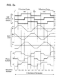
- Fig. 2(a) shows graphs of the various outputs of Hall effect sensors as measured over one full (360°) mechanical revolution of the rotor of multipole BLDC motor 5 installed in the mud pulser 10.
- Fig. 2(a) further shows the back emf signals generated during the BLDC motor 5's operation and the phase current supplied to the BLDC motor 5 from the motor control circuitry 300 during motor commutation.
- the BLDC motor 5 whose characteristics are depicted in Fig. 2(a) has two pairs of poles on its rotor and consequently, every 30° of mechanical rotation corresponds to 60° of an electrical cycle.
- the BLDC motor 5 in the present exemplary embodiment has three stator windings: A, B, and C. As shown in Fig. 2(a) , the three stator windings are electrically coupled such that the generated back emf signals are trapezoidal. In alternative embodiments (not depicted), the BLDC motor 5 may have more than three stator windings, and they may be electrically coupled to generate back emf signals of different waveforms (e.g., sinusoidal).
- Fig. 2(a) shows the output of three Hall effect sensors mounted in the BLDC motor 5.
- One sensor is mounted adjacent to each of the stator windings. Every 30° of mechanical rotation, which as mentioned above corresponds to 60° of an electrical cycle, the output of one of the Hall effect sensors Hall A, Hall B, and Hall C changes from high to low or vice-versa. Every 180° of a mechanical rotation, the outputs of the Hall effect sensors repeat.
- the Hall effect sensor outputs change every 30° of mechanical rotation, the BLDC motor 5 can be commutated by recognizing six different electrical sequences that are used during commutation: 1 through 6, as noted in Fig. 2(a) .
- the current that passes through the stator windings when the motor is commutated is depicted in the "Phase Current" graphs of Fig. 2(a) .
- the motor control circuitry 300 detects the electrical sequence for the motor based on the readings of the Hall effect sensors, and governs (commutates) the motor by sequentially applying a battery voltage across the different stator windings A, B, or C of the motor, depending on whether clockwise or counter-clockwise rotation is desired.
- the motor control circuitry 300 is configured to not use rotor position indications from any of Hall effect sensors Hall A, Hall B, or Hall C to make such determination. Instead, according to an embodiment, the motor control circuitry 300 determines a current angular rotation ⁇ of the rotor, using one of the methods schematically depicted in later figures.
- the back emf voltage on the graph labelled "A+B-” can be determined by measuring it across winding A; the back emf voltage on the graph labelled "B+/C-” can be determined by measuring it across winding B; and the back emf voltage on the graph labelled "C+/A-” can be determined by measuring it across winding C.
- the back emf voltage may be calculated from current values for current supplied to individual stator windings A, B, and/or C, using, for example, the method shown in Fig. 6 herein, and as further described herein.
- the methods described in this paragraph and in the paragraph above require commutation information in order to make the measurements.
- the overall current (I) supplied to the motor is measured and then multiplied with an average resistance (R) of the windings. This product is subtracted from an overall measured voltage supplied to the motor. The result is then multiplied by a constant k and the rotor angular rotation may be determined by time integrating this result.
- each of the Hall effect sensor output transitions corresponds to a phase transition in one of the back emf signals. This phase transition is also known as a "zero crossing".
- the motor control circuitry 300 by determining and counting these back emf voltage phase transitions, the motor control circuitry 300 is able to determine the number of rotations (or more specifically fractions of rotations) of motor 5 without relying on readings from the Hall Effect sensors.
- the exemplary BLDC motor 5 whose characteristics are depicted in Fig. 2(a) has two pairs of poles on its rotor.
- BLDC motors having more or fewer pairs of poles on its rotor can be used and the graphs shown in Fig. 2(a) will accordingly change.
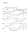
- the graphs of Fig. 2(b) depict characteristics of an exemplary BLDC motor that has a single pair of poles on its rotor.
- the output of Hall effect sensors are contrasted with the back emf signals measured across stator windings A, B and C.
- 60° of mechanical rotation corresponds to 60° of an electrical cycle.
- the phase transitions/zero crossings in the back emf signals are offset 30° from the corresponding edges in the signals from the Hall effect sensors.
- the motor control circuitry 300 can be configured to compensate for this 30° offset, and for any similar offset that may exist in BLDC motors of alternative embodiments, such that the back emf signals can still be used to efficiently and properly determine rotor angular rotation.
- BLDC motors having any suitable number of stator or rotor poles can be used.
- FIG. 3 there is shown a diagram of the motor control circuitry 300 used to commutate the motor 5, having Hall effect sensors Hall A, Hall B, and Hall C, positioned about the periphery of a rotor 5b of the motor 5.
- the Hall effect sensors may be placed on a stator 5c that is located around the rotor 5b.
- the motor control circuitry 300 includes a microcontroller 302 which, in the depicted embodiment, is a Microchip TM PIC18F2431 microcontroller manufactured by Microchip Technology Inc. of Chandler, Arizona, USA.
- any suitable controller such as a processor, microcontroller, programmable logic controller, field programmable gate array, can be used, or the functionality of the microcontroller 302 may be implemented using, for example, an application-specific integrated circuit.
- the microcontroller 302 includes a computer readable medium 322, such as flash memory, that stores instructions regarding how to commutate the motor.
- the microcontroller 302 controls commutation of the BLDC motor 5 by using, for example, pulse width modulation on outputs PWM[0....5], which are amplified using, for example, a field effect transistor (FET) driver 304.
- FET field effect transistor
- the IGBT driver 304 outputs the amplified PWM[0..5] outputs to a series of switched gates Q0...Q5, which when actuated by IGBT driver 304 via the feed through wires 24 in the sequence shown in Fig. 4 , allow one of the windings A, B, or C, as the case may be, to be energized, and another to be de-energized.
- battery 350 supplies, for example, 24V DC power for use in operating the microprocessor 302 and IGBT driver 304, and commutating the motor 5.
- Other configurations for the motor control circuitry 300 may be implemented.
- step 500 clockwise and counter-clockwise commutation arrays are initialized.
- step 501 a check is performed prior to commutating the motor.
- steps 502, 503, and 504 respective sensed values from each of Hall sensors are read into a variable "hval", which allows a determination to be made as to where the rotor position is in the sequence 1-6.
- step 505 If motor commutation is desired to be clockwise (step 505-determined by microprocessor 302), the values read into "hval" are used as a pointer (step 507) to determine where in the clockwise sequence of energization positions 1-6 the rotor is located, so that the clockwise commutation sequence may start (step 508) at the desired energization sequence 1-6 (ref. Fig. 4 ).
- step 506 the values read into "hval" are used as a pointer (step 506) to determine where in the counter-clockwise sequence of energization positions 1-6 the rotor is located, so that the counter-clockwise commutation sequence may start (step 509) at the desired energization sequence 1-6 (ref. Fig. 4 ).
- these approaches include but are not limited to (i) comparing the voltage of each of the feed through wires 24 to half the DC voltage (12.5V in the depicted embodiment) used to drive the BLDC motor 5; (ii) comparing the voltage of each of the feed through wires 24 to a virtual ground signal; or (iii) simply sampling the voltage of each of the feed through wires 24 and inputting that value directly into the microcontroller 302 for digitization and use.
- the result of the comparison is a square wave in which the wave is high when the back emf voltage is greater than zero and low when the back emf voltage is less than zero. Consequently, the microcontroller 302 can rely on edge detection to determine where the phase transitions of the back emf signals occur.
- a digitized version of the entire trapezoidal back emf signal may be input to the microcontroller 302.
- the microcontroller 302 compares the digitized back emf signal to a reference zero point.
- the microcontroller 302 may consider more or different information than zero crossings.
- the microcontroller 302 may additionally or alternatively utilize the entire waveform of the back emf signals to determine any one or more of their rate of change; maximum and minimum values; and overall shape in order to determine the number and when such phase transitions occur.
- Another manner of determining back emf voltages for use not in commutating the motor 5 but for determining the current angular rotation ⁇ of the motor 5, may be accomplished by calculating such values from sensed current values, and knowing the resistance of each of the stator windings.
- the back emf is proportional to the rotor speed, related by some known constant k.
- k may be determined by measuring the rotor speed when the motor runs unloaded on a known supply voltage. The winding resistance may be measured with the motor stalled. The back emf is measurable by measuring the supply voltage and subtracting the current times the winding resistance. The rotation of the rotor is then equal to the time-integral of the speed. The current term ensures that a heavily loaded motor, which would turn more slowly, is correctly monitored.
- An enhancement to the algorithm is to correct the known resistance for the effect of temperature, which rises linearly with the temperature.
- the motor circuitry 300 controls the motor 5, and in particular how to avoid overdriving the pilot valve 8 of the mud pulser 10 past the fully open or fully closed position and thereby wasting limited power of the battery 350.
- values of a current motor rotation ⁇ for an incremental time period ⁇ t, and a total value "d" of the motor rotation over a given time period when the pilot valve 8 is in the fully open or fully closed position are initially set to zero.
- the motor drive circuitry 300 is used to commutate the motor 5 in a clockwise manner if the pilot valve 8 is being closed, or in a counter-clockwise manner if the pilot valve 8 is being moved from the open to the closed position.
- a determination is made if there is any motor drive fault, by determining if there is any change in the values sensed by the Hall effect sensors.
- step 617 the microprocessor acquires (reads) voltage V from battery 350, and reads current IA, IB, or IC as applicable of the stator windings.
- Step 609 determines if the speed is negative (if so, it goes directly to step 613). If not, the current angular rotation ⁇ is determined in step 611 by a numerical integration approximation method, namely multiplying the calculated speed by a value of an incremental small time period ⁇ t, and adding the obtained value ⁇ to total angular rotation "d". Thereafter, at step 613, a determination is made if the total angular motor rotation "d" exceeds a predefined limit, namely the number of motor rotations required to drive the valve pilot 8 from a fully open to a fully closed position, or vice versa, and if so further rotation is ceased (step 617).
- a predefined limit namely the number of motor rotations required to drive the valve pilot 8 from a fully open to a fully closed position, or vice versa
- a first check is made to determine if the motor is drawing current in excess of a predetermined amount. If so, further motor rotation in that direction ceases.
- Fig. 6 shows an exemplary value of 4 A for the current limit. However, other values may be used depending on the motor and other conditions.
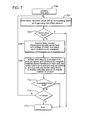
- Fig. 7 shows an alternative method of determining the total angular rotation "d" of motor 5 of a mud pulser 10, and using such determined value to control the mud pulser's operation and in particular the extent of travel of the pilot valve 8.
- initial consecutive steps 700, 701, and 703 correspond to initial steps 600, 601, and 603 of Fig. 6 , and thus, they will not be again repeated.
- the motor control circuitry 300 may continually sense (instead of calculating), in any of the manners indicated above, the back emf of the motor.
- the motor control circuitry 300 senses the back emf voltage from one of the three stator windings which is not energized at the given sampling time. Thereafter, as shown in step 705, the motor control circuitry 300 is configured to multiply the measured emf values by a constant k to produce the speed of the rotor, and to thereafter continuously integrate, between phase transitions in the sensed back emf, the speed over time to produce the current angular rotation ⁇ .
- Such determined amount ⁇ is summed with any earlier integration, to thereby calculate the total amount of angular rotation "d" of the rotor.
- steps 713, 714, and 715 of Fig. 7 are identical to steps 613, 615, and 617 of Fig. 6 .
- Fig. 8 shows yet a further alternative method of determining the total angular rotation "d" of a motor 5 of a mud pulser 10, and using such determined value to control the mud pulser's operation and in particular the extent of travel of a pilot valve 8.
- initial consecutive steps 800, 801, and 803 correspond to initial steps 600, 601, and 603 of Fig. 6 , and will not be again repeated.
- an overall voltage V supplied to the motor 5 is monitored, as is the overall current I supplied to motor.
- a step 809 may be inserted to check that the resultant speed is not a negative value. If the speed is negative, the process advances to step 813.
- step 811 assuming no negative speed value obtained, the resultant value of speed may be integrated over time to produce a value for the total angular rotation "d" of the rotor over such time interval.
- Remaining steps 813 and 815 are similar to steps 713 and 715 of Fig. 7 and thus, not described herein.
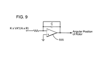
- Microprocessors which continually or not integrate values are well known to those skilled in the art. For example, one manner of continually integrating an obtained value of speed, as calculated in step 705 of Fig. 7 , and in step 811 of Fig. 8 , at least in an analog circuit, is to employ an operational amplifier.
- Fig. 9 shows an operational amplifier 555 which may be used in an analog method for integrating the numerical product of k ⁇ [V - (I ⁇ R)], as in the method depicted in Fig. 7 , step 705, and in the method depicted in Fig. 8 , step 811.
- Fig. 10 there is shown another method for operating a mud pulser 10.
- This method may be stored in the computer readable medium 322 of the microcontroller 302 or other microprocessor (not shown), or on any other suitable computer readable medium, including disc-based media such as CD-ROMs and DVDs, magnetic media such as hard drives and other forms of magnetic disk storage, semiconductor based media such as flash media, random access memory, and read only memory.
- disc-based media such as CD-ROMs and DVDs
- magnetic media such as hard drives and other forms of magnetic disk storage
- semiconductor based media such as flash media, random access memory, and read only memory.
- the microcontroller begins at step 1000 and proceeds to step 1001 to commutate the BLDC motor 5 by energizing and de-energizing stator windings A, B, and C in the manner described above.
- the commutation causes the rotor of the motor to rotate in a clockwise or counter-clockwise direction, typically (but not necessarily) from a position where the pilot valve 8 is in a fully open position, in which case the motor rotation is clockwise to cause the pilot valve 8 to move toward the closed position, or if in the fully closed position, the rotor rotates counter-clockwise to move the pilot valve 8 toward the fully open position.
- Steps 1001 and 1003 are similar to steps 701 and 703 of the method illustrated in Fig. 7 , and thus, these steps are not discussed herein.
- the motor control circuitry 300 is able to measure the back emf signals at step 1006 and identify and keep a count of the phase transitions that occur in the back emf signals at step 1008. Once the phase transitions are counted over a given period of time during which the motor has rotated, the total angular rotation "d" of the motor 5 can then be determined in step 1010.
- the extent of movement of the pilot valve 8 for a given angular rotation of the motor can be determined, and a limit in the angular rotation of the motor thereby can be determined to avoid unnecessary overdriving of the pilot valve 8 in the fully open or fully closed position.
- Step 1013 in Fig. 10 thus causes the motor control circuitry 300, after driving the motor 5, to determine whether the limit in the angular rotation of the motor has reached a pre-defmed limit. If yes, the motor is ceased to be driven in step 1015. If no, in an optional embodiment, a further query (step 1014 ) is made as to whether the motor current is greater than a predefined limit (to prevent overdriving the motor). If yes, the driving of the motor then ceases (step 1015). If no, driving of the motor continues with a return to step 1001.
- the microcontroller contained in motor control circuitry 300 is able to cause the BLDC motor 5 to rotate in clockwise or counter-clockwise directions.
- this motion of the motor 5 may be used to transmit "0" and "1" signals as discussed next.
- a high pressure or "1" signal can be sent by completely opening the pilot valve 8, e.g., by rotating the BLDC motor 5 counter-clockwise to cause the pilot valve 8 to retract from the valve seat/orifice 9 such that the pilot valve 8 does not impede mud flow through the valve orifice 9.
- a low pressure or "0" signal can be sent by closing the pilot valve 8, e.g., by rotating the BLDC motor 5 clockwise to cause the tip of the pilot valve 8 to step the valve seat/orifice 9, which prevents mud from flowing through the valve orifice 9.
- the microcontroller 302 can be programmed with the total number of motor rotations (including fractional portions or increments thereof) used to transition the pilot valve 8 from the completely closed position (i.e., when the pilot valve 8 is inserted as far as possible into the valve seat 9) to the completely opened position (i.e., when the pilot valve 8 is retracted as far as possible from the valve seat 9).
- the microcontroller 302 is able to determine where the tip of the pilot valve 8 is between the completely opened and completely closed positions.
- the microcontroller 302 is able to vary the flow rate of the mud through the pilot valve 8. In this way, the microcontroller 302 can control the height of the pressure pulses that the mud pulser 10 transmits, and send messages encoded using non-binary modulation schemes, such as quadrature amplitude modulation.
- the method includes a step 1100 of commutating the electric motor based on signals from one or more sensors attached to a stator of the electric motor; and a step 1102 of determining with a motor control circuitry, electrically connected to the electric motor, a total angular rotation of a rotor of the electric motor, based on a back emf voltage of one or more windings of the stator and independent of the signals from the one or more sensors.
- One or more of the exemplary embodiments discussed above provide an electric motor and a corresponding controller for commutating the motor based on sensor measurements and for determining a rotational position based on a sensorless approach. It should be understood that this description is not intended to limit the invention. On the contrary, the exemplary embodiments are intended to cover alternatives, modifications and equivalents, which are included in the spirit and scope of the invention as defined by the appended claims. Further, in the detailed description of the exemplary embodiments, numerous specific details are set forth in order to provide a comprehensive understanding of the claimed invention. However, one skilled in the art would understand that various embodiments may be practiced without such specific details.
Landscapes
- Engineering & Computer Science (AREA)
- Power Engineering (AREA)
- Control Of Motors That Do Not Use Commutators (AREA)
Applications Claiming Priority (1)
| Application Number | Priority Date | Filing Date | Title |
|---|---|---|---|
| US13/270,426 US9312798B2 (en) | 2011-10-11 | 2011-10-11 | Sensor commuated electric motor with sensorless angular position determination and method |
Publications (3)
| Publication Number | Publication Date |
|---|---|
| EP2595307A2 true EP2595307A2 (fr) | 2013-05-22 |
| EP2595307A3 EP2595307A3 (fr) | 2014-04-02 |
| EP2595307B1 EP2595307B1 (fr) | 2018-05-30 |
Family
ID=47263018
Family Applications (1)
| Application Number | Title | Priority Date | Filing Date |
|---|---|---|---|
| EP12187659.3A Not-in-force EP2595307B1 (fr) | 2011-10-11 | 2012-10-08 | Moteur électrique commuté à capteur avec détermination de position angulaire sans capteur et procédé |
Country Status (5)
| Country | Link |
|---|---|
| US (1) | US9312798B2 (fr) |
| EP (1) | EP2595307B1 (fr) |
| CN (1) | CN103051140B (fr) |
| CA (1) | CA2791507C (fr) |
| NO (1) | NO2595307T3 (fr) |
Cited By (1)
| Publication number | Priority date | Publication date | Assignee | Title |
|---|---|---|---|---|
| US10533413B2 (en) | 2015-02-10 | 2020-01-14 | Evolution Engineering Inc. | Method and apparatus for determining rotor position in a fluid pressure pulse generator |
Families Citing this family (15)
| Publication number | Priority date | Publication date | Assignee | Title |
|---|---|---|---|---|
| AU2011381085B2 (en) | 2011-11-14 | 2014-12-18 | Halliburton Energy Services, Inc. | Apparatus and method to produce data pulses in a drill string |
| CN104088628B (zh) * | 2014-06-27 | 2017-02-15 | 中国石油集团渤海钻探工程有限公司 | 基于四叶片三角阀型的连续相位相移键控调制方法 |
| WO2016039731A1 (fr) | 2014-09-09 | 2016-03-17 | Halliburton Energy Services, Inc. | Détermination de degré de déflexion de corps de sonde dans un dispositif de forage rotatif orientable |
| CA2961763C (fr) | 2014-09-19 | 2019-01-08 | Flow Control Llc. | Technique de commande de remplissage automatique |
| CA2920579A1 (fr) * | 2015-02-12 | 2016-08-12 | Justin C. LOGAN | Outil mesure de fond de puits pendant le forage au moyen d'un spectrometre et methode de fonctionnement dudit outil |
| KR20170051813A (ko) * | 2015-11-02 | 2017-05-12 | 현대자동차주식회사 | 모터 제어 방법 및 시스템 |
| CN105490617A (zh) * | 2015-12-21 | 2016-04-13 | 北京市普利门机电高技术公司 | 用于驱动电动机的方法和系统 |
| DE102016201074B4 (de) * | 2016-01-26 | 2020-07-09 | Baumüller Nürnberg GmbH | Verfahren zur Erfassung einer Lage eines rotierenden Zentralelements eines Elektromotors |
| US10074245B2 (en) | 2017-01-10 | 2018-09-11 | Woodward, Inc. | Force feel using a brushless DC motor |
| CN108869830A (zh) * | 2017-05-09 | 2018-11-23 | 浙江三花汽车零部件有限公司 | 电子膨胀阀、热管理组件、冷却系统以及电子膨胀阀制造方法 |
| US11698146B2 (en) | 2017-05-09 | 2023-07-11 | Zhejiang Sanhua Automotive Components Co., Ltd. | Electronic expansion valve, thermal management assembly, cooling system, and method for manufacturing electronic expansion valve |
| CN109854167A (zh) * | 2019-01-03 | 2019-06-07 | 中国石油集团长城钻探工程有限公司 | 无线绞车传感器 |
| EP3855257A1 (fr) * | 2020-01-22 | 2021-07-28 | Siemens Aktiengesellschaft | Procédé de surveillance d'une fonction protégée contre les erreurs de capteurs dans un moteur |
| US12095402B2 (en) * | 2021-03-25 | 2024-09-17 | Snap-On Incorporated | Controlling a brushless motor |
| DE102021108229A1 (de) | 2021-03-31 | 2022-10-06 | Ebm-Papst Mulfingen Gmbh & Co. Kg | Verfahren zur Blockadeerkennung eines Elektromotors |
Family Cites Families (31)
| Publication number | Priority date | Publication date | Assignee | Title |
|---|---|---|---|---|
| US4493200A (en) | 1983-03-10 | 1985-01-15 | Tapco Products Company, Inc. | Portable sheet bending brake |
| US4764711A (en) * | 1987-09-04 | 1988-08-16 | E-Systems, Inc. | Back emf loop closure |
| US5140245A (en) | 1990-09-24 | 1992-08-18 | Westinghouse Electric Corp. | Pmg-based position sensor and synchronous drive incorporating same |
| US5115415A (en) | 1991-03-06 | 1992-05-19 | Baker Hughes Incorporated | Stepper motor driven negative pressure pulse generator |
| US5486286A (en) * | 1991-04-19 | 1996-01-23 | Althin Medical, Inc. | Apparatus for performing a self-test of kidney dialysis membrane |
| JP3140146B2 (ja) | 1992-03-12 | 2001-03-05 | キヤノン株式会社 | レンズ駆動装置 |
| US5696430A (en) | 1993-02-22 | 1997-12-09 | General Electric Company | Circuit, motor, and method generating a signal representing back EMF in an energized motor winding |
| US5384527A (en) | 1993-05-12 | 1995-01-24 | Sundstrand Corporation | Rotor position detector with back EMF voltage estimation |
| US5461293A (en) | 1993-05-12 | 1995-10-24 | Sundstrand Corporation | Rotor position detector |
| US5495162A (en) | 1993-05-12 | 1996-02-27 | Sundstrand Corporation | Position-and-velocity sensorless control for starter generator electrical system using generator back-EMF voltage |
| US5333686A (en) | 1993-06-08 | 1994-08-02 | Tensor, Inc. | Measuring while drilling system |
| ITPN940019A1 (it) | 1994-03-30 | 1995-09-30 | Sole Spa | Motore a commutazione elettronica |
| US6016288A (en) | 1994-12-05 | 2000-01-18 | Thomas Tools, Inc. | Servo-driven mud pulser |
| US5747971A (en) | 1996-08-08 | 1998-05-05 | Sundstrand Corporation | Position and velocity sensorless control for a motor generator system operated as a motor using exciter impedance |
| US6104113A (en) | 1998-05-14 | 2000-08-15 | General Electric Company | Coil assembly for sensorless rotor angular position control of single phase permanent magnet motor |
| US6630809B2 (en) * | 2001-11-29 | 2003-10-07 | Ballard Power Systems Corporation | System and method for induction motor control |
| US6762575B2 (en) | 2002-06-25 | 2004-07-13 | Trimble Navigation Limited | Electronic rotor pointing with high angular resolution |
| US6891343B2 (en) * | 2003-03-14 | 2005-05-10 | Petersen Technology Corporation | Multiphase motors with single point sensing based commutation |
| US7564741B2 (en) | 2004-04-06 | 2009-07-21 | Newsco Directional And Horizontal Drilling Services Inc. | Intelligent efficient servo-actuator for a downhole pulser |
| CA2463354C (fr) | 2004-04-06 | 2011-02-15 | Dale F. Pratt | Servomoteur intelligent efficace avec capteur pour generateur d'impulsions de fond de trou |
| US7567047B2 (en) | 2004-06-30 | 2009-07-28 | Hamilton Sundstrand Corporation | Electric motor control strategies for using a low resolution position sensor |
| JP2006201148A (ja) * | 2004-12-22 | 2006-08-03 | Toshiba Mach Co Ltd | 信号処理装置、信号処理方法、信号処理プログラム、信号処理プログラムを記録した記録媒体、速度検出装置、サーボ機構 |
| JP2007236062A (ja) | 2006-02-28 | 2007-09-13 | Matsushita Electric Ind Co Ltd | モータ駆動装置及びモータ駆動方法並びにディスク駆動装置 |
| JP2008008739A (ja) * | 2006-06-29 | 2008-01-17 | Toshiba Mach Co Ltd | 信号処理装置、速度検出装置、サーボ機構 |
| GB2443415A (en) * | 2006-11-02 | 2008-05-07 | Sondex Plc | A device for creating pressure pulses in the fluid of a borehole |
| EP1978631A1 (fr) | 2007-04-05 | 2008-10-08 | Fem B.V. | Moteur sans balai triphasé, outil d'alimentation électrique d'un moteur sans balai triphasé |
| ITTO20070459A1 (it) | 2007-06-26 | 2008-12-27 | Emerson Appliance Motors Europe | Sistema di controllo senza sensori di posizione per un motore elettrico sincrono |
| US7638959B2 (en) | 2007-12-14 | 2009-12-29 | Hamilton Sundstrand Corporation | Method of operating a brushless motor wherein open loop and closed loop controllers utilize different commutation methods |
| US8242725B2 (en) * | 2008-04-15 | 2012-08-14 | Ford Global Technologies, Llc | Method for operating sensorless and brushless motors |
| GB2469128A (en) * | 2009-04-04 | 2010-10-06 | Dyson Technology Ltd | Generating control signals for an electric machine from a position sensor |
| CA2738271A1 (fr) * | 2011-04-28 | 2012-10-28 | Sondex Wireline Ltd. | Impulseur pour mesures en cours de forage de boue et methode de commande dudit impulseur |
-
2011
- 2011-10-11 US US13/270,426 patent/US9312798B2/en not_active Expired - Fee Related
-
2012
- 2012-10-04 CA CA2791507A patent/CA2791507C/fr active Active
- 2012-10-08 NO NO12187659A patent/NO2595307T3/no unknown
- 2012-10-08 EP EP12187659.3A patent/EP2595307B1/fr not_active Not-in-force
- 2012-10-11 CN CN201210383384.0A patent/CN103051140B/zh not_active Expired - Fee Related
Cited By (1)
| Publication number | Priority date | Publication date | Assignee | Title |
|---|---|---|---|---|
| US10533413B2 (en) | 2015-02-10 | 2020-01-14 | Evolution Engineering Inc. | Method and apparatus for determining rotor position in a fluid pressure pulse generator |
Also Published As
| Publication number | Publication date |
|---|---|
| NO2595307T3 (fr) | 2018-10-27 |
| US20130088361A1 (en) | 2013-04-11 |
| CA2791507C (fr) | 2020-10-27 |
| EP2595307A3 (fr) | 2014-04-02 |
| CN103051140B (zh) | 2017-07-11 |
| CN103051140A (zh) | 2013-04-17 |
| CA2791507A1 (fr) | 2013-04-11 |
| EP2595307B1 (fr) | 2018-05-30 |
| US9312798B2 (en) | 2016-04-12 |
Similar Documents
| Publication | Publication Date | Title |
|---|---|---|
| EP2595307B1 (fr) | Moteur électrique commuté à capteur avec détermination de position angulaire sans capteur et procédé | |
| EP2518266A2 (fr) | Générateur d'impulsions de boue de forage et son procédé de commande | |
| US7564741B2 (en) | Intelligent efficient servo-actuator for a downhole pulser | |
| US7417920B2 (en) | Reciprocating pulser for mud pulse telemetry | |
| US9638025B2 (en) | Mud pulser with poppet valve, having linear displacement determination means | |
| US7719439B2 (en) | Rotary pulser | |
| CN108071386B (zh) | 一种旋转式脉冲发射器和一种沿着钻柱传输信息的方法 | |
| EP2003771B1 (fr) | Commande sans capteur de boucle fermée de moteurs synchronisés et magnétiques en permanence | |
| GB2538639A (en) | Rotary pulser and method for transmitting information to the surface from a drill string down hole in a well | |
| US11371318B2 (en) | System and method for electrical control of downhole well tools | |
| US9157278B2 (en) | Apparatus including load driven by a motor coupled to an alternator | |
| KR102170677B1 (ko) | 액츄에이터를 이용한 백래쉬 조절장치 | |
| CA2551316C (fr) | Generateur d'impulsions rotatif | |
| CA2746081C (fr) | Commutateur de detection de position sans contact | |
| US6100662A (en) | Step motor stabilization control | |
| CA2603117C (fr) | Servomoteur intelligent et efficace avec joint dynamique pour generateur a impulsions de fond de trou | |
| CA2879026C (fr) | Pulseur de boue dote d'un distributeur a clapet et de mecanismes de determination de deplacement lineaire | |
| US7821178B2 (en) | Brush and brush housing arrangement to mitigate hydrodynamic brush lift in fluid-immersed electric motors | |
| US20240141779A1 (en) | Rotary pulser with regenerative control |
Legal Events
| Date | Code | Title | Description |
|---|---|---|---|
| PUAI | Public reference made under article 153(3) epc to a published international application that has entered the european phase |
Free format text: ORIGINAL CODE: 0009012 |
|
| AK | Designated contracting states |
Kind code of ref document: A2 Designated state(s): AL AT BE BG CH CY CZ DE DK EE ES FI FR GB GR HR HU IE IS IT LI LT LU LV MC MK MT NL NO PL PT RO RS SE SI SK SM TR |
|
| AX | Request for extension of the european patent |
Extension state: BA ME |
|
| PUAL | Search report despatched |
Free format text: ORIGINAL CODE: 0009013 |
|
| AK | Designated contracting states |
Kind code of ref document: A3 Designated state(s): AL AT BE BG CH CY CZ DE DK EE ES FI FR GB GR HR HU IE IS IT LI LT LU LV MC MK MT NL NO PL PT RO RS SE SI SK SM TR |
|
| AX | Request for extension of the european patent |
Extension state: BA ME |
|
| RIC1 | Information provided on ipc code assigned before grant |
Ipc: H02P 6/18 20060101AFI20140221BHEP |
|
| 17P | Request for examination filed |
Effective date: 20141002 |
|
| RBV | Designated contracting states (corrected) |
Designated state(s): AL AT BE BG CH CY CZ DE DK EE ES FI FR GB GR HR HU IE IS IT LI LT LU LV MC MK MT NL NO PL PT RO RS SE SI SK SM TR |
|
| 17Q | First examination report despatched |
Effective date: 20161207 |
|
| GRAP | Despatch of communication of intention to grant a patent |
Free format text: ORIGINAL CODE: EPIDOSNIGR1 |
|
| GRAJ | Information related to disapproval of communication of intention to grant by the applicant or resumption of examination proceedings by the epo deleted |
Free format text: ORIGINAL CODE: EPIDOSDIGR1 |
|
| GRAP | Despatch of communication of intention to grant a patent |
Free format text: ORIGINAL CODE: EPIDOSNIGR1 |
|
| INTG | Intention to grant announced |
Effective date: 20171109 |
|
| INTC | Intention to grant announced (deleted) | ||
| INTG | Intention to grant announced |
Effective date: 20171130 |
|
| GRAJ | Information related to disapproval of communication of intention to grant by the applicant or resumption of examination proceedings by the epo deleted |
Free format text: ORIGINAL CODE: EPIDOSDIGR1 |
|
| GRAR | Information related to intention to grant a patent recorded |
Free format text: ORIGINAL CODE: EPIDOSNIGR71 |
|
| GRAS | Grant fee paid |
Free format text: ORIGINAL CODE: EPIDOSNIGR3 |
|
| GRAA | (expected) grant |
Free format text: ORIGINAL CODE: 0009210 |
|
| INTC | Intention to grant announced (deleted) | ||
| INTG | Intention to grant announced |
Effective date: 20180418 |
|
| AK | Designated contracting states |
Kind code of ref document: B1 Designated state(s): AL AT BE BG CH CY CZ DE DK EE ES FI FR GB GR HR HU IE IS IT LI LT LU LV MC MK MT NL NO PL PT RO RS SE SI SK SM TR |
|
| REG | Reference to a national code |
Ref country code: GB Ref legal event code: FG4D |
|
| REG | Reference to a national code |
Ref country code: CH Ref legal event code: EP |
|
| REG | Reference to a national code |
Ref country code: AT Ref legal event code: REF Ref document number: 1004629 Country of ref document: AT Kind code of ref document: T Effective date: 20180615 |
|
| REG | Reference to a national code |
Ref country code: IE Ref legal event code: FG4D |
|
| REG | Reference to a national code |
Ref country code: DE Ref legal event code: R096 Ref document number: 602012046815 Country of ref document: DE |
|
| REG | Reference to a national code |
Ref country code: NO Ref legal event code: T2 Effective date: 20180530 |
|
| REG | Reference to a national code |
Ref country code: NL Ref legal event code: MP Effective date: 20180530 |
|
| REG | Reference to a national code |
Ref country code: LT Ref legal event code: MG4D |
|
| PG25 | Lapsed in a contracting state [announced via postgrant information from national office to epo] |
Ref country code: ES Free format text: LAPSE BECAUSE OF FAILURE TO SUBMIT A TRANSLATION OF THE DESCRIPTION OR TO PAY THE FEE WITHIN THE PRESCRIBED TIME-LIMIT Effective date: 20180530 Ref country code: CY Free format text: LAPSE BECAUSE OF FAILURE TO SUBMIT A TRANSLATION OF THE DESCRIPTION OR TO PAY THE FEE WITHIN THE PRESCRIBED TIME-LIMIT Effective date: 20180530 Ref country code: FI Free format text: LAPSE BECAUSE OF FAILURE TO SUBMIT A TRANSLATION OF THE DESCRIPTION OR TO PAY THE FEE WITHIN THE PRESCRIBED TIME-LIMIT Effective date: 20180530 Ref country code: BG Free format text: LAPSE BECAUSE OF FAILURE TO SUBMIT A TRANSLATION OF THE DESCRIPTION OR TO PAY THE FEE WITHIN THE PRESCRIBED TIME-LIMIT Effective date: 20180830 Ref country code: LT Free format text: LAPSE BECAUSE OF FAILURE TO SUBMIT A TRANSLATION OF THE DESCRIPTION OR TO PAY THE FEE WITHIN THE PRESCRIBED TIME-LIMIT Effective date: 20180530 Ref country code: SE Free format text: LAPSE BECAUSE OF FAILURE TO SUBMIT A TRANSLATION OF THE DESCRIPTION OR TO PAY THE FEE WITHIN THE PRESCRIBED TIME-LIMIT Effective date: 20180530 |
|
| PG25 | Lapsed in a contracting state [announced via postgrant information from national office to epo] |
Ref country code: GR Free format text: LAPSE BECAUSE OF FAILURE TO SUBMIT A TRANSLATION OF THE DESCRIPTION OR TO PAY THE FEE WITHIN THE PRESCRIBED TIME-LIMIT Effective date: 20180831 Ref country code: HR Free format text: LAPSE BECAUSE OF FAILURE TO SUBMIT A TRANSLATION OF THE DESCRIPTION OR TO PAY THE FEE WITHIN THE PRESCRIBED TIME-LIMIT Effective date: 20180530 Ref country code: RS Free format text: LAPSE BECAUSE OF FAILURE TO SUBMIT A TRANSLATION OF THE DESCRIPTION OR TO PAY THE FEE WITHIN THE PRESCRIBED TIME-LIMIT Effective date: 20180530 Ref country code: LV Free format text: LAPSE BECAUSE OF FAILURE TO SUBMIT A TRANSLATION OF THE DESCRIPTION OR TO PAY THE FEE WITHIN THE PRESCRIBED TIME-LIMIT Effective date: 20180530 |
|
| REG | Reference to a national code |
Ref country code: AT Ref legal event code: MK05 Ref document number: 1004629 Country of ref document: AT Kind code of ref document: T Effective date: 20180530 |
|
| PG25 | Lapsed in a contracting state [announced via postgrant information from national office to epo] |
Ref country code: NL Free format text: LAPSE BECAUSE OF FAILURE TO SUBMIT A TRANSLATION OF THE DESCRIPTION OR TO PAY THE FEE WITHIN THE PRESCRIBED TIME-LIMIT Effective date: 20180530 |
|
| PG25 | Lapsed in a contracting state [announced via postgrant information from national office to epo] |
Ref country code: CZ Free format text: LAPSE BECAUSE OF FAILURE TO SUBMIT A TRANSLATION OF THE DESCRIPTION OR TO PAY THE FEE WITHIN THE PRESCRIBED TIME-LIMIT Effective date: 20180530 Ref country code: SK Free format text: LAPSE BECAUSE OF FAILURE TO SUBMIT A TRANSLATION OF THE DESCRIPTION OR TO PAY THE FEE WITHIN THE PRESCRIBED TIME-LIMIT Effective date: 20180530 Ref country code: RO Free format text: LAPSE BECAUSE OF FAILURE TO SUBMIT A TRANSLATION OF THE DESCRIPTION OR TO PAY THE FEE WITHIN THE PRESCRIBED TIME-LIMIT Effective date: 20180530 Ref country code: PL Free format text: LAPSE BECAUSE OF FAILURE TO SUBMIT A TRANSLATION OF THE DESCRIPTION OR TO PAY THE FEE WITHIN THE PRESCRIBED TIME-LIMIT Effective date: 20180530 Ref country code: DK Free format text: LAPSE BECAUSE OF FAILURE TO SUBMIT A TRANSLATION OF THE DESCRIPTION OR TO PAY THE FEE WITHIN THE PRESCRIBED TIME-LIMIT Effective date: 20180530 Ref country code: AT Free format text: LAPSE BECAUSE OF FAILURE TO SUBMIT A TRANSLATION OF THE DESCRIPTION OR TO PAY THE FEE WITHIN THE PRESCRIBED TIME-LIMIT Effective date: 20180530 Ref country code: EE Free format text: LAPSE BECAUSE OF FAILURE TO SUBMIT A TRANSLATION OF THE DESCRIPTION OR TO PAY THE FEE WITHIN THE PRESCRIBED TIME-LIMIT Effective date: 20180530 |
|
| PG25 | Lapsed in a contracting state [announced via postgrant information from national office to epo] |
Ref country code: IT Free format text: LAPSE BECAUSE OF FAILURE TO SUBMIT A TRANSLATION OF THE DESCRIPTION OR TO PAY THE FEE WITHIN THE PRESCRIBED TIME-LIMIT Effective date: 20180530 Ref country code: SM Free format text: LAPSE BECAUSE OF FAILURE TO SUBMIT A TRANSLATION OF THE DESCRIPTION OR TO PAY THE FEE WITHIN THE PRESCRIBED TIME-LIMIT Effective date: 20180530 |
|
| REG | Reference to a national code |
Ref country code: DE Ref legal event code: R097 Ref document number: 602012046815 Country of ref document: DE |
|
| PLBE | No opposition filed within time limit |
Free format text: ORIGINAL CODE: 0009261 |
|
| STAA | Information on the status of an ep patent application or granted ep patent |
Free format text: STATUS: NO OPPOSITION FILED WITHIN TIME LIMIT |
|
| REG | Reference to a national code |
Ref country code: DE Ref legal event code: R119 Ref document number: 602012046815 Country of ref document: DE |
|
| 26N | No opposition filed |
Effective date: 20190301 |
|
| PG25 | Lapsed in a contracting state [announced via postgrant information from national office to epo] |
Ref country code: SI Free format text: LAPSE BECAUSE OF FAILURE TO SUBMIT A TRANSLATION OF THE DESCRIPTION OR TO PAY THE FEE WITHIN THE PRESCRIBED TIME-LIMIT Effective date: 20180530 |
|
| REG | Reference to a national code |
Ref country code: CH Ref legal event code: PL |
|
| REG | Reference to a national code |
Ref country code: BE Ref legal event code: MM Effective date: 20181031 |
|
| PG25 | Lapsed in a contracting state [announced via postgrant information from national office to epo] |
Ref country code: MC Free format text: LAPSE BECAUSE OF FAILURE TO SUBMIT A TRANSLATION OF THE DESCRIPTION OR TO PAY THE FEE WITHIN THE PRESCRIBED TIME-LIMIT Effective date: 20180530 Ref country code: LU Free format text: LAPSE BECAUSE OF NON-PAYMENT OF DUE FEES Effective date: 20181008 |
|
| REG | Reference to a national code |
Ref country code: IE Ref legal event code: MM4A |
|
| PG25 | Lapsed in a contracting state [announced via postgrant information from national office to epo] |
Ref country code: DE Free format text: LAPSE BECAUSE OF NON-PAYMENT OF DUE FEES Effective date: 20190501 |
|
| PG25 | Lapsed in a contracting state [announced via postgrant information from national office to epo] |
Ref country code: BE Free format text: LAPSE BECAUSE OF NON-PAYMENT OF DUE FEES Effective date: 20181031 Ref country code: LI Free format text: LAPSE BECAUSE OF NON-PAYMENT OF DUE FEES Effective date: 20181031 Ref country code: FR Free format text: LAPSE BECAUSE OF NON-PAYMENT OF DUE FEES Effective date: 20181031 Ref country code: CH Free format text: LAPSE BECAUSE OF NON-PAYMENT OF DUE FEES Effective date: 20181031 |
|
| PG25 | Lapsed in a contracting state [announced via postgrant information from national office to epo] |
Ref country code: IE Free format text: LAPSE BECAUSE OF NON-PAYMENT OF DUE FEES Effective date: 20181008 |
|
| PG25 | Lapsed in a contracting state [announced via postgrant information from national office to epo] |
Ref country code: AL Free format text: LAPSE BECAUSE OF FAILURE TO SUBMIT A TRANSLATION OF THE DESCRIPTION OR TO PAY THE FEE WITHIN THE PRESCRIBED TIME-LIMIT Effective date: 20180530 |
|
| PG25 | Lapsed in a contracting state [announced via postgrant information from national office to epo] |
Ref country code: MT Free format text: LAPSE BECAUSE OF NON-PAYMENT OF DUE FEES Effective date: 20181008 |
|
| PG25 | Lapsed in a contracting state [announced via postgrant information from national office to epo] |
Ref country code: TR Free format text: LAPSE BECAUSE OF FAILURE TO SUBMIT A TRANSLATION OF THE DESCRIPTION OR TO PAY THE FEE WITHIN THE PRESCRIBED TIME-LIMIT Effective date: 20180530 |
|
| PG25 | Lapsed in a contracting state [announced via postgrant information from national office to epo] |
Ref country code: PT Free format text: LAPSE BECAUSE OF FAILURE TO SUBMIT A TRANSLATION OF THE DESCRIPTION OR TO PAY THE FEE WITHIN THE PRESCRIBED TIME-LIMIT Effective date: 20180530 |
|
| PG25 | Lapsed in a contracting state [announced via postgrant information from national office to epo] |
Ref country code: HU Free format text: LAPSE BECAUSE OF FAILURE TO SUBMIT A TRANSLATION OF THE DESCRIPTION OR TO PAY THE FEE WITHIN THE PRESCRIBED TIME-LIMIT; INVALID AB INITIO Effective date: 20121008 Ref country code: MK Free format text: LAPSE BECAUSE OF NON-PAYMENT OF DUE FEES Effective date: 20180530 |
|
| PG25 | Lapsed in a contracting state [announced via postgrant information from national office to epo] |
Ref country code: IS Free format text: LAPSE BECAUSE OF FAILURE TO SUBMIT A TRANSLATION OF THE DESCRIPTION OR TO PAY THE FEE WITHIN THE PRESCRIBED TIME-LIMIT Effective date: 20180930 |
|
| PGFP | Annual fee paid to national office [announced via postgrant information from national office to epo] |
Ref country code: NO Payment date: 20211011 Year of fee payment: 10 Ref country code: GB Payment date: 20211007 Year of fee payment: 10 |
|
| REG | Reference to a national code |
Ref country code: NO Ref legal event code: MMEP |
|
| GBPC | Gb: european patent ceased through non-payment of renewal fee |
Effective date: 20221008 |
|
| PG25 | Lapsed in a contracting state [announced via postgrant information from national office to epo] |
Ref country code: NO Free format text: LAPSE BECAUSE OF NON-PAYMENT OF DUE FEES Effective date: 20221031 |
|
| PG25 | Lapsed in a contracting state [announced via postgrant information from national office to epo] |
Ref country code: GB Free format text: LAPSE BECAUSE OF NON-PAYMENT OF DUE FEES Effective date: 20221008 |